
A319
0.5mm Pitch Board to Board Connector
DF17 Series
s
Features
1.
Solution of Connector Damage
Caused when Mobile
Phone is Dropped
DF17 series are the connector which has
been developed mainly for the mobile
phone.
Connector Problems Involving in Mobile phone
Example:
The following problems can be solved;
"Connector Damage Caused when Mobile
phone is Dropped"
"Electrical Discontinuity in Printed Circuit
Board is Fixed (Fastened by screws)"
Especially, in regard to the resistance to the
drop shock, Hirose has developed a new
connector structure utilizing its unique
technology, and greatly enhanced the
resistance to the drop shock.
In broad variation development, the connector
can be utilized in wide fields of LCD equipment,
miniature information terminal equipment and
so on, in addition to mobile phones.
A320
2. Performance Enhancement
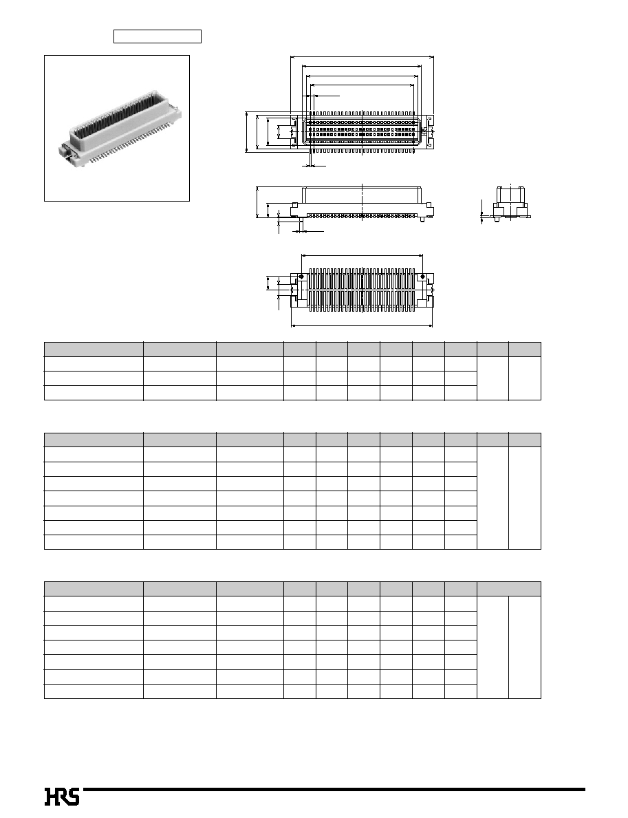
The receptacle is designed in a BOX structure and has also
enhanced shock-proof, pinch-proof and scoop-proof performance.
In addition, the receptacle contact has employed the high scoop-proof
bellows type.
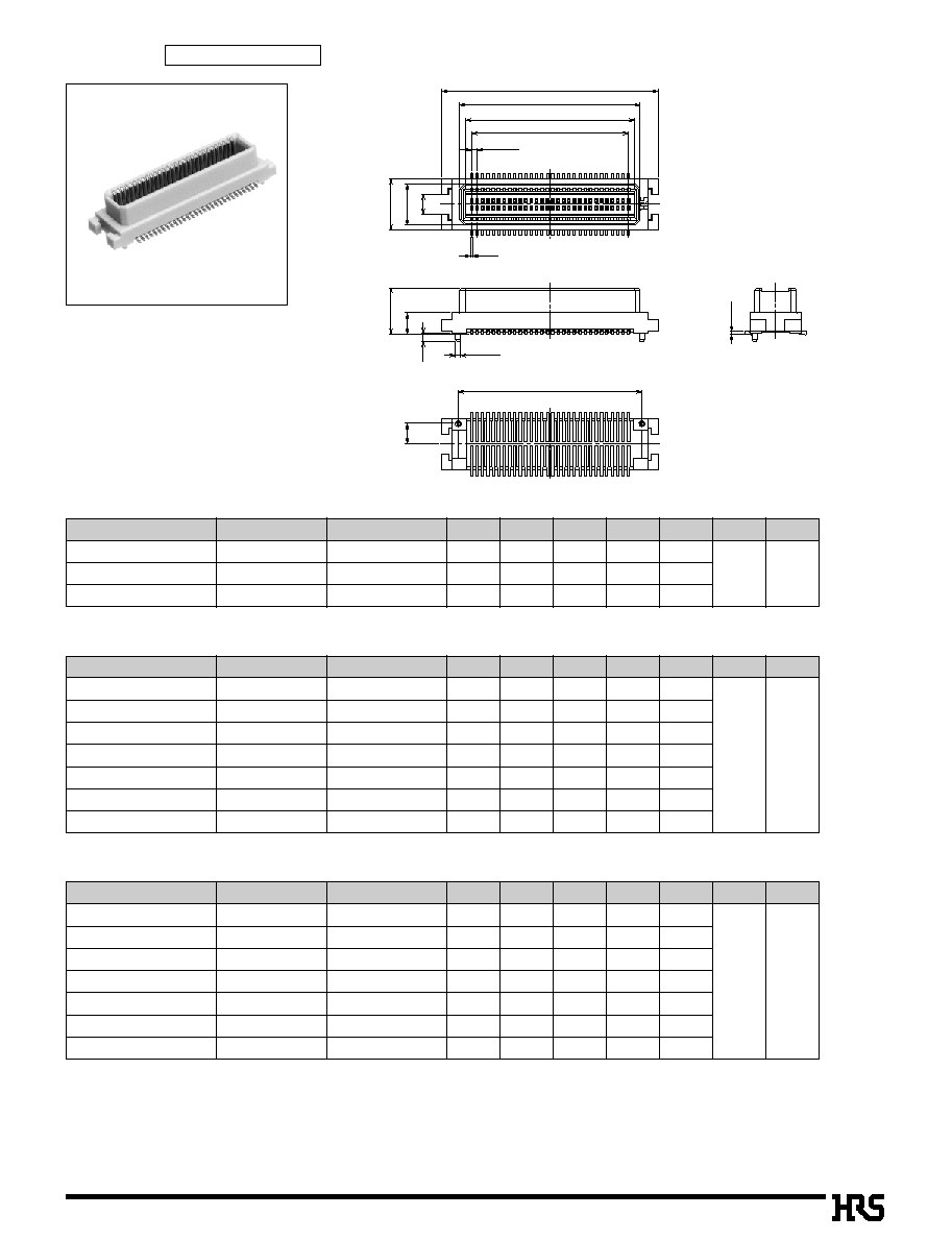
3. With Metal Fitting available
In order to grade up the strength against the mechanical stress,
the metal fitting specification is also available.
4. Broad Variations in Contact Number
The connectors are lined up per 10 contacts between 20 and 80
contacts to take countermeasures for multi-signalization.
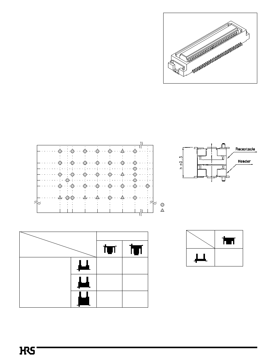
5. Stacking Height 4 to 8mm
The stacking height can be selected (per milimeter) between 4mm and
8mm in combination of the receptacle with the header.
s
Applications
Mobile phones, LCD, miniature equipment and so on
Note : The stacking height doesn't
include the solder paste thickness.
20
8
7
6
6.5
5
5.5
4
26 30
40
50
60
70
80
100 (Contacts)
Stacking
(mm)
: Available
: Under plan
DF17#(
M
)-
*
DP-0.5V
2.0
2.5
4.0
3.0
4.0
5mm
5.5mm
7mm
6mm
6.5mm
8mm
DF17#(
M
)-
*
DS-0.5V
DF17(1.0H)-
*
DP-0.5V
Header
Receptacle DF17(3.0H)-
*
DS-0.5V
4mm
Header
Receptacle
A321
100V DC
150V AC/1 minute
100mA
Frequency: 10 to 55 Hz, single amplitude of 0.75 mm, 2 hours in each of the 3 directions.
96 hours at temperature of 40Á and humidity of 90% to 95%
(-55
Á
: 30 minutes 5 to 35
Á
: 10 minutes 85
Á
: 30 minutes 5 to 35
Á
: 10 minutes) 5 cycles
50 cycles
Reflow: At the recommended temperature profile
Manual soldering: 300Á for 3 seconds
500M
ohms
min.
No flashover or insulation breakdown.
60m ohms max.
No electrical discontinuity of 1µs or more
Contact resistance: 60m ohms max Insulation resistance:250M ohms min
Contact resistance: 60m ohms max:Insulation resistance: 500M ohms min
Contact resistance: 60m ohms
No deformation of components affecting performance.
1. Insulation Resistance
2. Withstanding voltage
3. Contact Resistance
4. Vibration
5.
Humidity (Steady state)
6. Temperature Cycle
7. Durability (Mating/un-mating)
8. Resistance to
Soldering heat
Item
Specification
Condition
s
Product Specifications
Rating
Current rating
Voltage rating
0.3A
50V AC
Operating Temperature Range
Operating Humidity Range
Storage Temperature Range
Storage Humidity Range
-10 to 60
Á
(Note 2)
40 to 70
%
-35 to 85
Á
(Note 1)
40 to 80
%
Note 1: Includes temperature rise caused by current flow.
Note 2: The term "storage" refers to products stored for long period of time prior to mounting and use. Operating Temperature Range and
Humidity range covers non conducting condition of installed connectors in storage, shipment or during transportation.
Note1: DF17(0.3)-
*
DS-0.5V : Contact area: gold plating/lead area: flash gold plated
DF17(4.0)-
*
DS-0.5V : Contact area: gold plating/lead area: tin-lead plated
DF17(4.0)-
*
DP-0.5V : Contact area: gold plating/lead area: tin-lead plated
Note2: The header gold plated product:Contact area: gold plating/lead area: tin-lead plated
DF17(1.0H)-
*
DS-0.5V only: Contact area: gold plating/lead area: flash gold plated
s
Material
Product
Part
Receptacle
Header
Insulator
Contact
Metal Fitting
Insulator
Contact
Metal Fitting
Polyamide
Phosphor copper
Phosphor copper
Polyamide
Phosphor copper
Phosphor copper
White
Gold plated (Note 1)
Tin-lead plated
White
Gold plated (Note 2)
Tin-lead plated
UL94V-0
---------------
---------------
UL94V-0
---------------
---------------
Material
Finish
Remarks
B
Ordering Information
Please determine the specific product. If needed, please select and orderproducts from the product No. as listed on catalog page
A322~A325.
DF17
#
(
**
)
-
*
DS - 0.5 V (
**
)
1
2
3
4
5
6
8
7
q
Receptacle/Header
Product height
The stacking height can be determined by adding the
figures in parentheses to receptacle and header.
Number of Contacts
20,26,30,40,50,6,70,80contacts
Connector Type
DS: Receptacle
DP: Header
Contact Pitch: 0.5mm
Contact Type
V: Straight SMT
Packaging Type (50): Gold plated, embossed tape packaging
(51): Gold plated, tube packaging
3
4
5
6
7
8
2
1
DF17
DF17A
DF17B
DF17C
Fitting
K
K
Boss
K
K
Series Name: DF17
Type
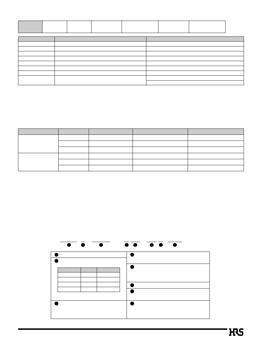
A322
q
Stacking Height: 4mm
s
Receptacle
With metal fitting
20
26
30
40
50
60
70
80
10.0
11.5
12.5
15.0
17.5
20.0
22.5
25.0
0
6.8
0
8.3
0
9.3
11.8
14.3
16.8
19.3
21.8
0
5.5
0
7.0
0
8.0
10.5
13.0
15.5
18.0
20.5
0
4.5
0
6.0
0
7.0
9.5
12.0
14.5
17.0
19.5
0
7.0
0
8.5
0
9.5
12.0
14.5
17.0
19.5
22.0
0
9.8
11.3
12.3
14.8
17.3
19.8
22.3
24.8
3.5
3.0
q
Stacking Height: 5mm, 7mm
q
Stacking Height: 6mm, 8mm
A
B
C
D
E
F
G
H
Number of Contacts
CL No.
683-0002-2-51
683-0241-3-51
683-0003-5-51
683-0004-8-51
683-0005-0-51
683-0006-3-51
683-0007-6-51
683-0008-9-51
Part Number
DF17(3.0)-20DS-0.5V(51)
DF17(3.0)-26DS-0.5V(51)
DF17(3.0)-30DS-0.5V(51)
DF17(3.0)-40DS-0.5V(51)
DF17(3.0)-50DS-0.5V(51)
DF17(3.0)-60DS-0.5V(51)
DF17(3.0)-70DS-0.5V(51)
DF17(3.0)-80DS-0.5V(51)
26
30
60
11.5
12.5
20.0
0
8.3
0
9.3
16.8
0
7.0
0
8.0
15.5
0
6.0
0
7.0
14.5
0
8.5
0
9.5
17.0
11.3
12.3
19.8
3.0
3.0
A
B
C
D
E
F
G
H
Number of Contacts
CL No.
683-0253-2-51
683-0268-0-51
683-0361-5-51
Part Number
DF17(3.0H)-26DS-0.5V(51)
DF17(3.0H)-30DS-0.5V(51)
DF17(3.0H)-60DS-0.5V(51)
20
30
40
50
60
70
80
10.0
12.5
15.0
17.5
20.0
22.5
25.0
0
6.8
0
9.3
11.8
14.3
16.8
19.3
21.8
0
5.5
0
8.0
10.5
13.0
15.5
18.0
20.5
0
4.5
0
7.0
0
9.5
12.0
14.5
17.0
19.5
0
7.0
0
9.5
12.0
14.5
17.0
19.5
22.0
0
9.8
12.3
14.8
17.3
19.8
22.3
24.8
4.5
4.0
A
B
C
D
E
F
G
H
Number of Contacts
CL No.
683-0042-7-51
683-0043-0-51
683-0044-2-51
683-0045-5-51
683-0046-8-51
683-0047-0-51
683-0048-3-51
Part Number
DF17(4.0)-20DS-0.5V(51)
DF17(4.0)-30DS-0.5V(51)
DF17(4.0)-40DS-0.5V(51)
DF17(4.0)-50DS-0.5V(51)
DF17(4.0)-60DS-0.5V(51)
DF17(4.0)-70DS-0.5V(51)
DF17(4.0)-80DS-0.5V(51)
Note 1. In regard to this product, the embossed tape packaging is the standard packaging. (1000 pcs./ reel.)
If the (50) tube packaging is required, please contact HRS company.
Note 2. If the without boss specification is required, please contact HRS sales department.
1.9
0.2
1.8
C
ÿ
0.5
4.7
P
=
0.5
D
E
B
A
0.7
H
G
1.5
5.7
3.9
0.2
F
A
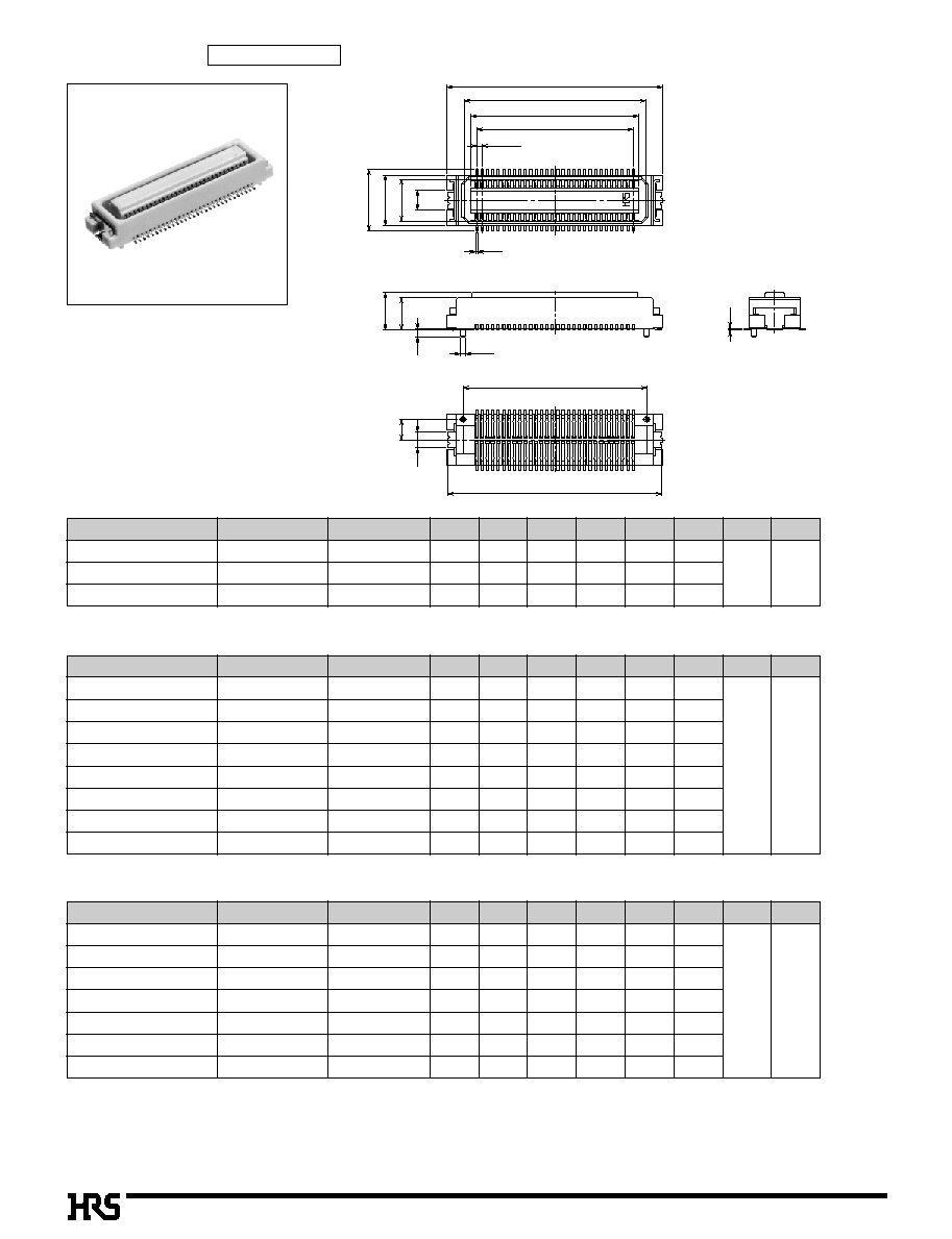
A323
s
Receptacle
Without metal fitting
1.9
0.2
1.8
C
ÿ
0.5
4.7
P
=
0.5
D
E
B
A
0.7
H
G
3.9
0.2
A
20
26
30
40
50
60
70
80
10.0
11.5
12.5
15.0
17.5
20.0
22.5
25.0
0
6.8
0
8.3
0
9.3
11.8
14.3
16.8
19.3
21.8
0
5.5
0
7.0
0
8.0
10.5
13.0
15.5
18.0
20.5
0
4.5
0
6.0
0
7.0
9.5
12.0
14.5
17.0
19.5
0
7.0
0
8.5
0
9.5
12.0
14.5
17.0
19.5
22.0
3.5
3.0
q
Stacking Height: 5mm, 7mm
q
Stacking Height: 6mm, 8mm
A
B
C
D
E
G
H
Number of Contacts
CL No.
683-0012-6-51
683-0242-6-51
683-0013-9-51
683-0014-1-51
683-0015-4-51
683-0016-7-51
683-0017-0-51
683-0018-2-51
Part Number
DF17A(3.0)-20DS-0.5V(51)
DF17A(3.0)-26DS-0.5V(51)
DF17A(3.0)-30DS-0.5V(51)
DF17A(3.0)-40DS-0.5V(51)
DF17A(3.0)-50DS-0.5V(51)
DF17A(3.0)-60DS-0.5V(51)
DF17A(3.0)-70DS-0.5V(51)
DF17A(3.0)-80DS-0.5V(51)
26
30
60
11.5
12.5
20.0
0
8.3
0
9.3
16.8
0
7.0
0
8.0
15.5
0
6.0
0
7.0
14.5
0
8.5
0
9.5
17.0
3.0
3.0
q
Stacking Height: 4mm
A
B
C
D
E
G
H
Number of Contacts
CL No.
683-0254-5-51
683-0269-2-51
683-0362-8-51
Part Number
DF17A(3.0H)-26DS-0.5V(51)
DF17A(3.0H)-30DS-0.5V(51)
DF17A(3.0H)-60DS-0.5V(51)
20
30
40
50
60
70
80
10.0
12.5
15.0
17.5
20.0
22.5
25.0
0
6.8
0
9.3
11.8
14.3
16.8
19.3
21.8
0
5.5
0
8.0
10.5
13.0
15.5
18.0
20.5
0
4.5
0
7.0
9.5
12.0
14.5
17.0
19.5
0
7.0
0
9.5
12.0
14.5
17.0
19.5
22.0
4.5
4.0
A
B
C
D
E
G
H
Number of Contacts
CL No.
683-0052-0-51
683-0053-3-51
683-0054-6-51
683-0055-9-51
683-0056-1-51
683-0057-4-51
683-0058-7-51
Part Number
DF17A(4.0)-20DS-0.5V(51)
DF17A(4.0)-30DS-0.5V(51)
DF17A(4.0)-40DS-0.5V(51)
DF17A(4.0)-50DS-0.5V(51)
DF17A(4.0)-60DS-0.5V(51)
DF17A(4.0)-70DS-0.5V(51)
DF17A(4.0)-80DS-0.5V(51)
Note 1.In regard to this product, the embossed tape packaging is the standard packaging. (1000 pcs./ reel.)
If the (50) tube packaging is required, please contact HRS company.
Note 2.If the without boss specification is required, please contact HRS sales department.
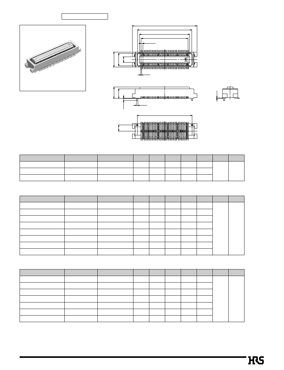
A324
4.0
H
s
Header
With metal fitting
q
Stacking Height: 5mm, 6mm
q
Stacking Height: 7mm, 8mm
Note 1. In regard to this product, the embossed tape packaging is the standard packaging. (1000 pcs./reel.)
If the (50) tube packaging is required, please contact HRS company.
Note 2. If the without boss specification is required, please contact HRS sales department.
20
30
40
50
60
70
80
10.0
12.5
15.0
17.5
20.0
22.5
25.0
0
6.7
0
9.2
11.7
14.2
16.7
19.2
21.7
0
5.6
0
8.1
10.6
13.1
15.6
18.1
20.6
0
4.5
0
7.0
0
9.5
12.0
14.5
17.0
19.5
0
7.0
0
9.5
12.0
14.5
17.0
19.5
22.0
0
9.8
12.3
14.8
17.3
19.8
22.3
24.8
4.3
2.0
A
B
C
D
E
F
G
H
Number of Contacts
CL No.
683-0082-1-51
683-0083-4-51
683-0084-7-51
683-0085-0-51
683-0086-2-51
683-0087-5-51
683-0088-8-51
Part Number
DF17(2.0)-20DP-0.5V(51)
DF17(2.0)-30DP-0.5V(51)
DF17(2.0)-40DP-0.5V(51)
DF17(2.0)-50DP-0.5V(51)
DF17(2.0)-60DP-0.5V(51)
DF17(2.0)-70DP-0.5V(51)
DF17(2.0)-80DP-0.5V(51)
20
30
40
50
60
70
80
10.0
12.5
15.0
17.5
20.0
22.5
25.0
0
6.7
0
9.2
11.7
14.2
16.7
19.2
21.7
0
5.6
0
8.1
10.6
13.1
15.6
18.1
20.6
0
4.5
0
7.0
0
9.5
12.0
14.5
17.0
19.5
0
7.0
0
9.5
12.0
14.5
17.0
19.5
22.0
0
9.8
12.3
14.8
17.3
19.8
22.3
24.8
6.3
A
B
C
D
E
F
G
Number of Contacts
CL No.
683-0122-4-51
683-0123-7-51
683-0124-0-51
683-0125-2-51
683-0126-5-51
683-0127-8-51
683-0128-0-51
Part Number
DF17(4.0)-20DP-0.5V(51)
DF17(4.0)-30DP-0.5V(51)
DF17(4.0)-40DP-0.5V(51)
DF17(4.0)-50DP-0.5V(51)
DF17(4.0)-60DP-0.5V(51)
DF17(4.0)-70DP-0.5V(51)
DF17(4.0)-80DP-0.5V(51)
B
E
P
=
0.5
D
C
4.7
A
1.8
0.7
ÿ
0.5
5.7
3.8
0.25
0.2
H
G
1.5
1.9
F
A
q
Stacking Height: 4mm
26
30
60
11.5
12.5
20.0
0
8.2
0
9.2
16.7
0
7.1
0
8.1
15.6
0
6.0
0
7.0
14.5
0
8.5
0
9.5
17.0
11.3
12.3
19.8
3.3
1.0
A
B
C
D
E
F
G
H
Number of Contacts
CL No.
683-0257-3-51
683-0272-7-51
683-0365-6-51
Part Number
DF17(1.0H)-26DP-0.5V(51)
DF17(1.0H)-30DP-0.5V(51)
DF17(1.0H)-60DP-0.5V(51)
A325
s
Header
Without metal fitting
20
30
40
50
60
70
80
10.0
12.5
15.0
17.5
20.0
22.5
25.0
0
6.7
0
9.2
11.7
14.2
16.7
19.2
21.7
0
5.6
0
8.1
10.6
13.1
15.6
18.1
20.6
0
4.5
0
7
.0
9.5
12
.0
14.5
17
.0
19.5
0
7
.0
0
9.5
12
.0
14.5
17
.0
19.5
22
.0
4.3
2
q
Stacking Height: 5mm, 6mm
q
Stacking Height: 7mm, 8mm
A
B
C
D
E
G
H
Number of Contacts
CL No.
683-0092-5-51
683-0093-8-51
683-0094-0-51
683-0095-3-51
683-0096-6-51
683-0097-9-51
683-0098-1-51
Part Number
DF17A(2.0)-20DP-0.5V(51)
DF17A(2.0)-30DP-0.5V(51)
DF17A(2.0)-40DP-0.5V(51)
DF17A(2.0)-50DP-0.5V(51)
DF17A(2.0)-60DP-0.5V(51)
DF17A(2.0)-70DP-0.5V(51)
DF17A(2.0)-80DP-0.5V(51)
20
30
40
50
60
70
80
10.0
12.5
15.0
17.5
20.0
22.5
25.0
0
6.7
0
9.2
11.7
14.2
16.7
19.2
21.7
0
5.6
0
8.1
10.6
13.1
15.6
18.1
20.6
0
4.5
0
7
.0
9.5
12
.0
14.5
17
.0
19.5
0
7
.0
0
9.5
12
.0
14.5
17
.0
19.5
22
.0
6.3
4
A
B
C
D
E
G
H
Number of Contacts
CL No.
683-0132-8-51
683-0133-0-51
683-0134-3-51
683-0135-6-51
683-0136-9-51
683-0137-1-51
683-0138-4-51
Part Number
DF17A(4.0)-20DP-0.5V(51)
DF17A(4.0)-30DP-0.5V(51)
DF17A(4.0)-40DP-0.5V(51)
DF17A(4.0)-50DP-0.5V(51)
DF17A(4.0)-60DP-0.5V(51)
DF17A(4.0)-70DP-0.5V(51)
DF17A(4.0)-80DP-0.5V(51)
Note 1. In regard to this product, the embossed tape packaging is the standard packaging. (1000 pcs./reel.)
If the (50) tube packaging is required, please contact HRS company.
Note 2. If the without boss specification is required, please contact HRS sales department.
B
E
P
=
0.5
D
C
4.7
A
1.8
0.7
ÿ
0.5
3.8
0.25
0.2
H
G
1.9
A
q
Stacking Height: 4mm
26
30
60
11.5
12.5
20.0
0
8.2
0
9.2
16.7
0
7.1
0
8.1
15.6
0
6.0
0
7.0
14.5
0
8.5
0
9.5
17.0
3.0
3.0
A
B
C
D
E
G
H
Number of Contacts
CL No.
683-0258-6-51
683-0273-0-51
683-0366-9-51
Part Number
DF17A(1.0H)-26DP-0.5V(51)
DF17A(1.0H)-30DP-0.5V(51)
DF17A(1.0H)-60DP-0.5V(51)

A326
S
Receptacle
4.3
Header
4
.0
s
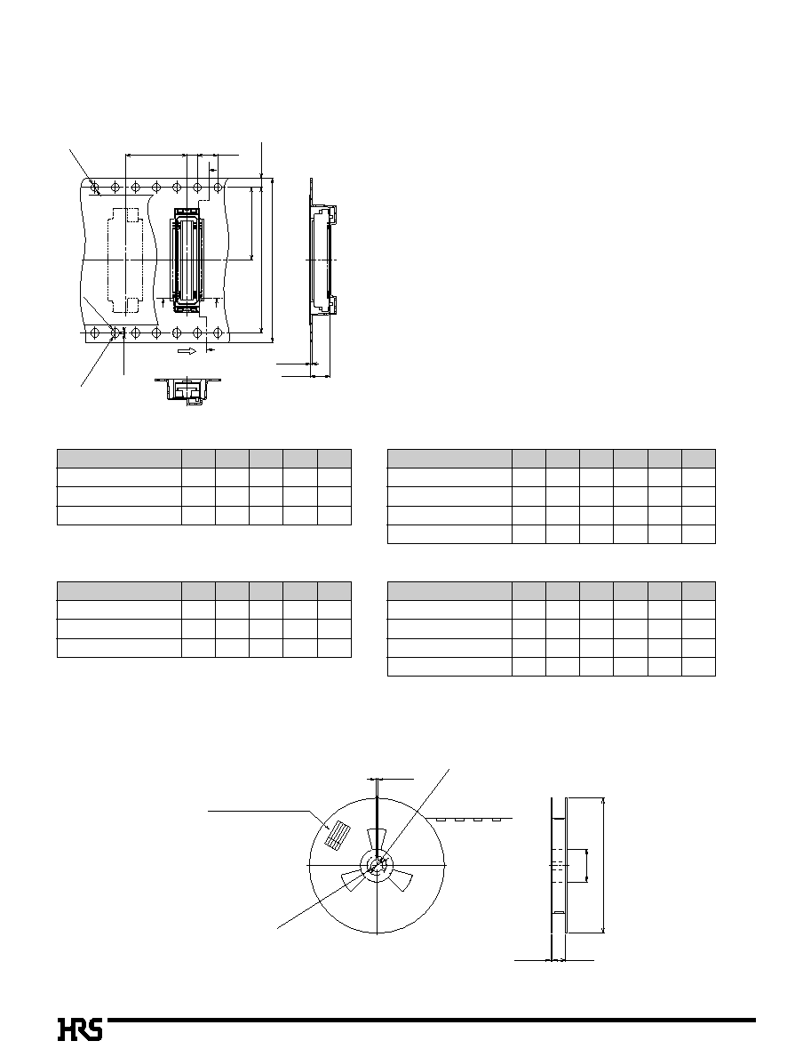
PCB mounting pattern with Metal Fitting
q
Receptacle
q
Header
Number of Contacts
D
E
J
K
20
0
4.5
0
7.0
10.4
0
7.6
30
0
7.0
0
9.5
12.9
10.1
40
0
9.5
12.0
15.4
12.6
50
12.0
14.5
17.9
15.1
60
14.5
17.0
20.4
17.6
70
17.0
19.5
22.9
20.1
80
19.5
22.0
25.4
22.6
*
The recommended solder paste
thickness is 150
µ
m.
Note 1.
If the pattern is included in the shaded area, and not treated
with resist, it could touch the connector contact.
Note 2. If the boss isn't included, the boss hole shown in the above figure
isn't required.
ÿ
0.6
+
0.05
0
S
0
_
0.05
6.3
+
0.1
0
1.9
±
0.02
P
=
0.5
±
0.02
D
±
0.03
E
±
0.03
K
0
_
0.1
J
+
0.1
0
0.25
±
0.02
2.1
+
0.1
0

A327
S
Receptacle
4.3
Header
4
.0
Note 1.
If the pattern is included in the shaded area, and not treated
with resist, it could touch the connector contact.
Note 2. If the boss isn't included, the boss hole shown in the above figure
isn't required.
s
PCB mounting pattern without Metal Fitting
q
Receptacle
q
Header
Number of Contacts
D
E
20
0
4.5
0
7.0
30
0
7.0
0
9.5
40
0
9.5
12.0
50
12.0
14.5
60
14.5
17.0
70
17.0
19.5
80
19.5
22.0
ÿ
0.6
+
0.05
0
S
0
_
0.05
6.3
+
0.1
0
P
=
0.5
±
0.02
D
±
0.03
E
±
0.03
0.125
±
0.02
0.625
±
0.02
1.9
±
0.02
0.25
±
0.02
*
The recommended solder paste
thickness is 150
µ
m.
A328
s
Packaging Specification
q
Embossed Carrier Tape Dimensions
s
Receptacle
Connector
L
N
P
Q
R
DF17#(3.0)-20DS-0.5V
11.5
24
3.8
24.4
330
DF17#(3.0)-30DS-0.5V
11.5
24
3.8
24.4
330
DF17#(3.0)-40DS-0.5V
11.5
24
3.8
24.4
330
Connector
L
M
N
P
Q
R
DF17#(3.0)-50DS-0.5V
14.2
28.4
32
3.8
32.4
330
DF17#(3.0)-60DS-0.5V
14.2
28.4
32
3.8
32.4
330
DF17#(3.0)-70DS-0.5V
20.2
40.4
44
3.8
44.4
330
DF17#(3.0)-80DS-0.5V
20.2
40.4
44
3.8
44.4
330
Connector
L
N
P
Q
R
DF17#(4.0)-20DS-0.5V
11.5
24
4.8
24.4
330
DF17#(4.0)-30DS-0.5V
11.5
24
4.8
24.4
330
DF17#(4.0)-40DS-0.5V
11.5
24
4.8
24.4
330
Connector
L
M
N
P
Q
R
DF17#(4.0)-50DS-0.5V
14.2
28.4
32
4.8
32.4
330
DF17#(4.0)-60DS-0.5V
14.2
28.4
32
4.8
32.4
330
DF17#(4.0)-70DS-0.5V
20.2
40.4
44
4.8
44.4
330
DF17#(4.0)-80DS-0.5V
20.2
40.4
44
4.8
44.4
330
q
Reel Dimensions
1.75±0.1
ÿ1.5
+
0.1
0
12±0.1
2±0.1
4±0.1
L±0.1
M±0.1
N±0.3
0.2±0.05
R0.75
+0.15
0
R0.75
+0.150
0.3±0.1
P±0.15
Unreeling direction
Y-Y
Y
X
Y
X-X
X
ÿ13±0.2
ÿ21±0.8
2±0.5
(ÿ
80
)
ÿR±2
2±0.5
Q
+2
0
Product name label
ÿ1.5 Lead hole depth

A329
s
Header
Connector
L
N
P
Q
R
DF17#(2.0)-20DP-0.5V
11.5
24
4.6
24.4
330
DF17#(2.0)-30DP-0.5V
11.5
24
4.6
24.4
330
DF17#(2.0)-40DP-0.5V
11.5
24
4.6
24.4
330
Connector
L
M
N
P
Q
R
DF17#(2.0)-50DP-0.5V
14.2
28.4
32
4.6
32.4
330
DF17#(2.0)-60DP-0.5V
14.2
28.4
32
4.6
32.4
330
DF17#(2.0)-70DP-0.5V
20.2
40.4
44
4.6
44.4
330
DF17#(2.0)-80DP-0.5V
20.2
40.4
44
4.6
44.4
330
Connector
L
N
P
Q
R
DF17#(4.0)-20DP-0.5V
11.5
24
6.6
24.4
380
DF17#(4.0)-30DP-0.5V
11.5
24
6.6
24.4
380
DF17#(4.0)-40DP-0.5V
11.5
24
6.6
24.4
380
Connector
L
M
N
P
Q
R
DF17#(4.0)-50DP-0.5V
14.2
28.4
32
6.6
32.4
380
DF17#(4.0)-60DP-0.5V
14.2
28.4
32
6.6
32.4
380
DF17#(4.0)-70DP-0.5V
20.2
40.4
44
6.6
44.4
380
DF17#(4.0)-80DP-0.5V
20.2
40.4
44
6.6
44.4
380
q
Reel Dimensions
1.75±0.1
ÿ1.5
+
0.1
0
12±0.1
2±0.1
4±0.1
L±0.1
M±0.1
N±0.3
0.2±0.05
R0.75
+
0.1
5
0
R0.75
+0.150
0.3±0.1
P±0.15
Unreeling direction
Y
X
Y
X
Y-Y
X-X
ÿ13±0.2
ÿ21±0.8
2±0.5
(ÿ
80
)
ÿR±2
2±0.5
Q
+2
0
Product name label
ÿ1.5 Lead hole depth
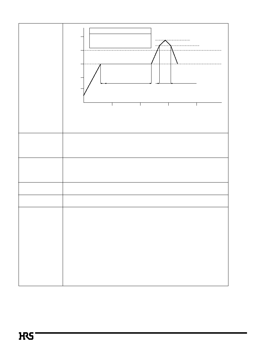
250
Á
200
Á
150
Á
100
Á
50
Á
0
Á
0SSEC
50SSEC
100SSEC
150SSEC
200SSEC
Time
Soldering area
Preheating area
240
Á
max.
220
Á
Temperature
Preheating area
IR reflow condition
150
Á
for 100 to 120 seconds
235
Á
5
Á
for 10 seconds max.
220
Á
min for 10 to 30 seconds
Soldering area
A330
s
Precautions
s
The header is designed in a structure where contacts are exposed. Touching it with bare
hands would cause contact failure or electrostatic element damage.
s
Where no board is mounted, the insertion or extraction will cause damage or contact deformation.
s
Avoid retaining the board with the connector only, and fix the board by any other means than the connector.
s
Excessive scoop insertion or extraction may result in damage.
s
In the manual soldering process, don't carry out the flux coating which will cause a flux blister on the connector.
s
The color phase of this product may be slightly different from that of the formed product
according to the manufacturing lot. However, the difference doesn't affect the performance.
Soldering iron temperature: 290
±
10
Á
oldering time: Within 2 seconds
0.15mm
Max 0.2mm in the connector center area, based on the both connector edges
Refer to the "Nylon Connector Use Hand book".
Note 1. Maximum twice action is allowed under the same condition. However, the interval between
the first and second actions must be maintained at the room temperature.
Note 2.The temperature indicates the board surface temperature of the connector lead area.
1. Recommended
Temperature Profile
(SMT)
6. Cautions
2. Recommended Manual
Soldering Condition
(SMT)
3. Recommended
Screen Thickness
(SMT)
4. Board Warp(SMT)
5. Cleaning Condition