
1
DF19 Series
NEW
2000.5
,,,,
,,,,
,,,,,
,,,,,
,,,
,,
,,,,
,,,,
,,,,,
,,,,,,,
,,
,,
,,
,,,,
,,,,
,,
,,
,,,,,,,,,,
,,,,,,
,,,,,,,,,,
,,,,
,,,,,
,,
,,
,,
,,,,,,,
,,,,
,,,,
Drawing of mated connectors
on a DF19G -
*
P-1H board
,,
,,
,,,,,,,
,,
,,
,,
,,,,
,,
,,,,,,,,,,
,,,,,,,,,,
,,,,,,
,,,,,,
,,,,,
,,,
,,
,,,,
,,,,
,,,,,,,,,,
,,,,
,,
,,
,,
,,,,,,,
,,,,
,,,,
,,,,
For connection
of cables
On-board type
Offset type
Reverse offset type
For connection
of FPC
For connection of
fine coaxial cables
,,
,,,,,,,
,,
,,
,,
,,,,
,,
,,,,,,,,,,
,,,,,,
,,
,,,,,
,,,
,,
,,,,
,,,,
,,,,,,,,,,
,,,,
,,
,,
,,
,,,,,,,
,,,,,,,
,,,,
,,,,
,,,,
,,
,,,,,,,,,,
,,,,,,
,,
,,,,
,,
,,,,,,,
,,,,
,,
,,,
,,,,,,,,,,
,,,,,,,,,,
,,
,,
,,
,,,,,,,
,,,,
,,
,,
,,,,
,,,,
,,,,
,,,,
s
Features
1. Ultra Low Profile
FPC type: Max. 1.7 mm thick
Discrete Wire & Coaxial 1.5 mm thick
2. SMT HEADERS Suit all Sockets
Each header can connect to three different sockets (cable, FPC,
and fine coaxial cable type.
(Note: Fine coaxial cable type is under development.)
3. Standardised Outer Dimensions
The three sockets have the same outside dimensions to allow
complete Flexibility.
4. Many Variations
There are headers of the on-board, offset, and reverse offset types
to accommodate all designs.
5. Connection to a Metal GROUND Plate
Ground lines can be connected to a metal shell for shielding.
s
Application
LCDs, notebook personal computers, small OA machines, and small consumer products
1 mm-Pitch Low Profile Connector System for Wire to PCB Applications
Suitable for use with Discrete Wire, FPC or Fine Coaxial Cable.
Drawing of mated connectors
on a DF19K-
*
P-1H board
Drawing of mated connectors
on a DF19L-
*
P-1H board
Drawing of mated connectors
on a DF19KR-
*
P-1H board

2
s
Product Specifications
s
Material
Rating
Rated current
Rated voltage
AWG#28
:
1A
AWG#30
:
0.5A
AWG#32
:
0.3A
FPC
:
0.5A
Fine coaxial cable AWG# 40: 0.3A
AC100V
Operating temperature range
Operating humidity range
Storage temperature range
Storage humidity range
-35
~
85
Á
Note 1
-35
~
85
Á
Note 2
-
20
~
80%
-10
~
60
Á
Note 2
-
40
~
70%
Measure at DC100V.
300 V AC, applied for one minute.
Measure at 100 mA.
Measure with a steel pin with thickness of 0.2
±
0.005.
Frequency: 10 Hz to 55 Hz, amplitude of 0.75 mm in 3 directions, 2h
Temperature of 40
±
2
≠
C, humidity of 90% to 95%, duration 96h
(-55-C: 30 min -> 5-C to 35-C: 10 min -> 85-C: 30 min -> 5-C to 35-C: 10 min ) 5 cycles
50 mechanical-operation cycles
Reflow: At the recommended temperature profile, manual soldering: iron temperature 300-C for 3s
500MW or more
No flashover or breakdown
30mW or less (50mW or less for FPC)
MIN 0.2N
(
20gf
),
MAX 3N
(
300gf
)
No electrical discontinuity for 1
µ
s or more
Contact resistance: specified value or less, insulation resistance: 500MW or more
Contact resistance: specified value or less, insulation resistance: 500MW or more
Contact resistance: specified value or less
No melting of resin portion, which affects performance
1.Insulation resistance
2.Voltage proof
3.Contact resistance
4.Insertion-Extraction Force
(per Contact)
5.Vibration
6.Damp heat
7.Temperature Cycling
8.Mechanical operation
9.Resistance to soldering heat
Item
Specification
Conditions
Note1: Tinning is Whisker free
UL standard
UL94V-0
----------
----------
UL94V-0
----------
----------
UL94V-0
----------
----------
UL94V-0
----------
----------
----------
Product
Part
Material
Color / Finish
Pin header
Socket
Crimp-Contact
FPC socket
Ground plate for FPC
Socket for fine coaxial cables
Ground plate for fine coaxial cables
Insulation
Terminal
Ground Plate
Insulation
Ground Plate
Terminal
Insulation
Terminal
Ground Plate
Insulation
Terminal
Ground Plate
Ground Plate
Polyamide resin
Phosphor bronze
Phosphor bronze
Polyamide resin
Stainless steel
Phosphor bronze
Polyamide resin
Phosphor bronze
Stainless steel
LCP resin
Phosphor bronze
Phosphor bronze
Phosphor bronze
Grey
Selective Gold Plating
Tin Plated
Grey
Tin Plated
Gold Plated
Grey
Selective Gold Plating
Tin Plated
Grey
Selective Gold Plating
Tin Plated
Tin Plated
Note1: Includes the temperature rise due to current flow.
Note2: The term storage refers to unused products prior to PCB mounting that is being stored for long periods.
The operating temperature and humidity range are applicable to connectors not carrying current. After PCB assembly or
temporary storage during transportation.
Note3: The aforementioned specifications are representative of this series. For information on specific parts, confirm with Sales Office.

3
s
Part Number Construction
DF 19 # -
*
*
P - 1 H
1
4
5
6
2
3
7
DF 19 # -
*
*
S - 1 F - GND
1
4
5
6
2
3
7
8
Series Name
:
DF
Profile
:
s
Pin header
G
:
On-board type (1.65 mm from the board)
K
:
Offset type (1.0 mm from the board)
L
:
Offset type (1.1 mm from the board)
KR
:
Reverse offset type of DF19K
(1.0 mm from the board)
s
Crimp socket
None
:
Without grounding shell
G
:
With grounding shell (protected for EMI)
s
FPC socket
G
:
Specification for connection with ground
shell
s
Ground plate for FPC
G
:
Specification for connection with ground
shell
s
Socket for coaxial fine cables
G
:
Specification for connection with ground shell
s
Ground plate for fine coaxial cables
G
:
Specification for connection with ground shell
1
Number of contacts
:
8,14,20,30... (Note 1)
2
3
4
Series No.
:
19
5
Connector type
S
:
Single row socket
P
:
Single row pin header
Contact pitch : 1mm
Wiring type / terminal profile
H
:
Right angle SMT
C
:
Crimp socket
F
:
FPC socket
SD
:
Socket for fine coaxial cables
Part for installation
GND
:
Ground plate (Note 2)
(Note 1) Be careful, as the number of contacts differ depending on the profile.
(Note 2) The FPC and coaxial fine cable types always use a ground plate.
Symbol
2830
:
AWG#28
~
30
3032
:
AWG#30
~
32
Type
SCF
:
Socket contact reel Packaging
Plating
A
:
Gold plating
Specification
None
:
10 000 pieces per reel
41
:
20 000 pieces per reel
The type name DF19 represents a specific product specification.
To order a product, specify the type from pages 4 to 9.
q
Connector
DF19 - 2830 SCF A (
*
* *
*
)
3
3
1
1
2
2
4
q
Terminal
6
7
8
4
4
s
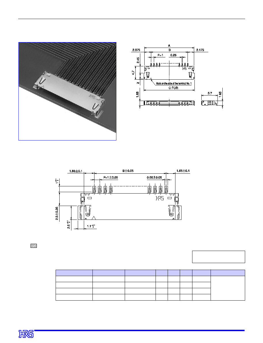
Right Angle Pin Header (SMT)
(On-board Type)
B
Recommended PCB Layout
,,,,,,,,,,,,
,,,,,,,,,,,,
,,,,,,,,,,,,
,,,,,,,,,,,,
Note1:
Masked area (hatched). Pattern in this area must be protected by resist.
Specification No.
* *
, (
* *
)
(59): Gold plating, Tape and reel packaging
HRS No.
Product No.
Number of poles
A
B
C
Width of emboss
Remarks
CL685-0021-0-
* *
CL685-0004-0-
* *
CL685-0006-6-
* *
CL685-0015-7-
* *
DF19G-
1
8P-1H (
* *
)
DF19G-14P-1H (
* *
)
DF19G-20P-1H (
* *
)
DF19G-30P-1H (
* *
)
8
14
20
30
11.55
17.55
23.55
33.55
7
13
19
29
11.95
17.95
23.95
33.95
24
44
44
44
1.65 mm from the
board
Unit: mm
Assembled Header
Note1: Specify the number of reels to order tape and reel packaging (1 000 pieces per reel).
5
Specification No.
* *
, (
* *
)
(59): Gold plating
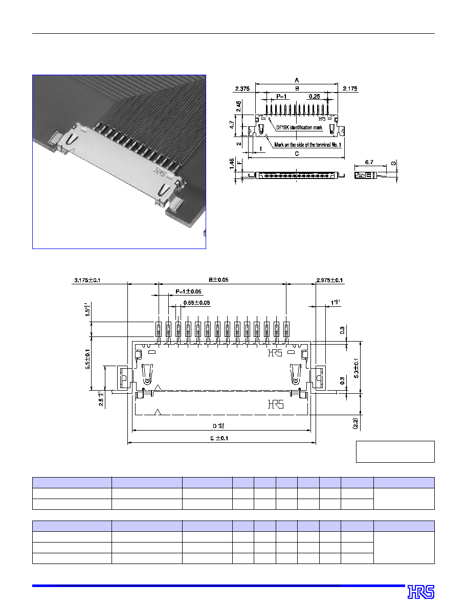
s
Right Angle Pin Header (SMT)
(Offset Type)
B
Recommended PCB Layout
Unit: mm
HRS No.
Product No.
Number of poles
A
B
C
D
E
Width of emboss
Remarks
CL685-0008-1-
* *
CL685-0032-6-
* *
DF19K-20P-1H (
* *
)
DF19K-30P-1H (
* *
)
20
30
23.55
33.55
19
29
26.55
36.55
24.15
34.15
25.15
35.15
44
56
1.0 mm from the
board
HRS No.
Product No.
Number of poles
A
B
C
D
E
Width of emboss
Remarks
CL685-0003-8-
* *
CL685-0019-8-
* *
CL685-0016-0-
* *
DF19L-14P-1H (
* *
)
DF19L-20P-1H (
* *
)
DF19L-30P-1H (
* *
)
14
20
30
17.55
23.55
33.55
13
19
29
20.55
26.55
36.55
18.15
24.15
34.15
19.15
25.15
35.15
44
44
56
1.1 mm from the
board
Note1: Specify the number of reels to order tape and reel packaging (1 000 pieces per reel).
Assembled Header

6
s
Right Angle Pin Header (SMT)
(Reverse Offset Type)
s
Recommended PCB Layout
Unit: mm
HRS No.
Product No.
Number of poles
A
B
C
D
E
Width of emboss
Remarks
CL685-0024-8-
* *
CL685-0023-5-
* *
DF19KR-14P-1H (
* *
)
DF19KR-20P-1H (
* *
)
14
20
17.55
23.55
13
19
20.55
26.55
18.15
24.15
19.15
25.15
44
44
1.0 mm from the
board
Specification No.
* *
, (
* *
)
(59): Gold plating
Note1: Specify the number of reels to order tape and reel packaging (1 000 pieces per reel).
Assembled Header
7
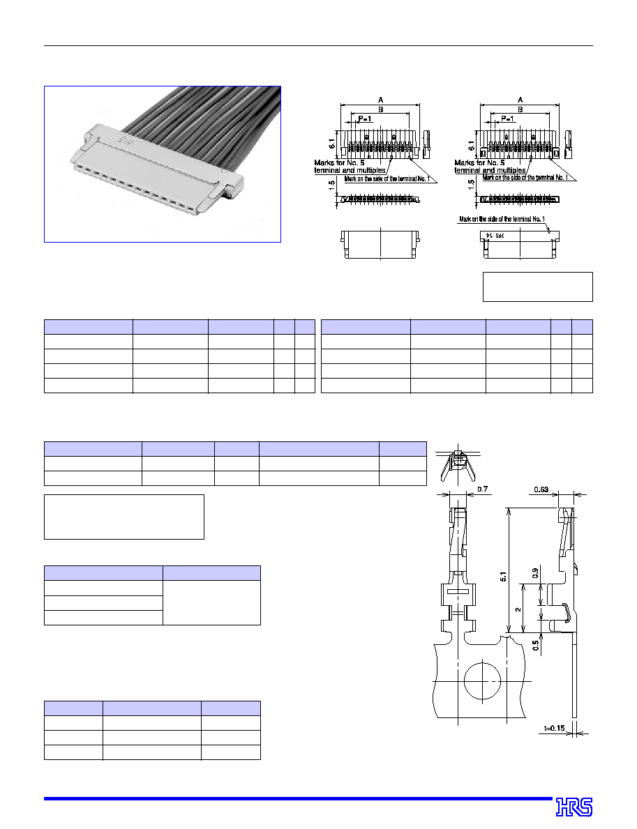
s
Single Row Socket (Discrete Wire)
s
Socket Crimp Contact
Specification No.
* * ,
(
* *
)
None : 1 Reel 10,000 pieces per reel
(41) : 1 Reel 20,000 pieces per reel
HRS No.
Product No.
Type
Quantity
Color / Finish
685-0001-2-
685-0002-5-41
DF19-2830SCF (
* *
)
DF19-3032SCF (
* *
)
Reel terminal
Reel terminal
10,000 pieces per reel
20,000 pieces per reel
Gold plating
Gold plating
Applicable wire size (core wire composition)
Sheath diameter
AWG#28 (7 strands/0.127 mm)
AWG#30 (7 strands/0.1 mm)
AWG#32 (7 strands/0.08 mm)
ÿ
0.5
~ ÿ
0.6mm
Product No.
Type
HRS No.
AP105-DF19S
CM-105
HT302/DF19S
Applicator
Press
Manual crimping tool
CL901-4571-3
CL901-0005-4
CL550-0284-7
Note1: Product is not guaranteed when non-specified tools are used.
Note2: Terminals are cut for manual crimping tool use.
Note1: Please contact us when you use wires other than those specified in the table.
q
Applicable Wire (tinned soft conductor)
q
Recommended Crimp Tooling
q
Recommended Wire
q
UL1571
q
Strip Length
q
1.2
~
1.9mm
Assembled Socket
DF19-
*
S-1C
DF19G-
*
S-1C
Specification No.
* * ,
(
* *
)
None: 1 pack (100 pieces)
Note1: Products are sold in bulk packs. To order, specify the number of packs (100 pieces per pack).
Product No.
Number of poles A
B
HRS No.
Product No.
Number of poles A
B
HRS No.
CL685-0029-1-
* *
CL685-0012-9-
* *
CL685-0011-6-
* *
CL685-0013-1-
* *
DF19 - 8S-1C (
* *
)
DF19 -14S-1C (
* *
)
DF19 -20S-1C (
* *
)
DF19 -30S-1C (
* *
)
8
14
20
30
11.5
17.5
23.5
33.5
7
13
19
29
CL685-0022-2-
* *
CL685-0005-3-
* *
CL685-0007-9-
* *
CL685-0014-4-
* *
DF19G - 8S-1C (
* *
)
DF19G -14S-1C (
* *
)
DF19G -20S-1C (
* *
)
DF19G -30S-1C (
* *
)
8
14
20
30
11.5
17.5
23.5
33.5
7
13
19
29
Unit: mm

8
s
Single Row Socket (For FPC Cable)
,,,
,,,
,,,
,,,
,,,
,,,
,,,
,,,
,,
,,
,,
,,
,,
,,
,,
,,
,,,
,,,
,,,
,,,
,,
,,
,,
,,
,,,,,,,,
,,,,,,,,
,,,,,,,,
,,,,,,,,
,,,,,,,,
,,,,,,,,
Note1: Wiring of FPC requires a socket and a ground plate.
s
Ground Plate for FPC
Type
HRS No.
Desk-top tool (for 14 core wires)
Desk-top tool (for 20 core wires)
Desk-top tool (for 30 core wires)
CL902-4514-6
CL902-4513-3
CL902-4518-7
Product No.
DF19G-14S/PR-MD2
DF19G-20S/PR-MD2
DF19G-30S/PR-MD2
Note1: Product is not guaranteed unless Hirose approved tools are used.
Note1:See page 12 for the
assembling method.
q
Applicable Assembling Tools
Assembled Socket
Unit: mm
HRS No.
Product No.
Number of Contacts
A
B
C
D
E
CL685-0017-2-
* *
CL685-0009-4-
* *
CL685-0033-9-
* *
DF19G-14S-1F (
* *
)
DF19G-20S-1F (
* *
)
DF19G-30S-1F (
* *
)
14
20
30
17.5
23.5
33.5
17.1
23.1
33.1
13
19
29
15.6
21.6
31.6
14
20
30
Note1: Products are sold in bulk packs. To order, specify the number of packs (100 pieces per pack).
Specification No.
* *,
(
* *
)
None: 1 pack (100 pieces)
Unit: mm
HRS No.
Product No.
Number of Contacts
A
B
C
CL685-0018-5-
* *
CL685-0010-3-
* *
CL685-0034-1-
* *
DF19G-14S-1F-GND (
* *
)
DF19G-20S-1F-GND (
* *
)
DF19G-30S-1F-GND (
* *
)
14
20
30
14.4
20.4
30.4
14.35
20.35
30.35
15.75
21.75
31.75
Note1: Products are sold in bulk packs. To order, specify the number of packs (100 pieces per pack).
Specification No.
* *
, (
* *
)
None: 1 pack (100 pieces)

9
s
Single Row Socket (Fine Coaxial Cable) ... (Under development)
Assembled Coaxial Socket
Specification No.
* *,
(
* *
)
None: 1 pack (100 pieces)
q
Applicable Wire (Fine Coaxial Cable) ... Planned
Applicable wire size (core wire composition) Sheath diameter
AWG#40(7strands/0.03mm)
ÿ
0.3
~ ÿ
0.4mm
Note1: The products will be sold in bulk packs (100 pieces per
pack). To order, specify the number of packs.
Product No.
Number of poles
HRS No.
DF19G-14S-1SD (
* *
)
DF19G-20S-1SD (
* *
)
14
20
-----------
-----------

10
B
Drawing of Tape and Reel Dimensions (as per JIS-C-0806)
q
DF19G-
*
P-1H
q
DF19K-
*
P-1H
q
DF19L-
*
P-1H
q
DF19KR-
*
P-1H
Insertion connector Number of Contacts
A
B
C
D
E
F
Remarks
DF19G -
1
8P -1H
DF19G -14P -1H
DF19G -20P -1H
DF19G -30P -1H
DF19K -20P -1H
DF19K -30P -1H
DF19L
-14P -1H
DF19L
-20P -1H
DF19L
-30P -1H
DF19KR -14P -1H
DF19KR -20P -1H
0
8
14
20
30
20
30
14
20
30
14
20
24
44
44
56
44
56
44
44
56
44
44
--------
40.4
40.4
50.2
40.4
52.4
40.4
40.4
52.4
40.4
40.4
11.5
20.2
20.2
26.2
20.2
26.2
20.2
20.2
26.2
20.2
20.2
16.1
22.1
28.1
38.1
28.1
38.1
22.1
28.1
38.1
22.1
28.1
24.4
44.4
44.4
56.4
44.4
56.4
44.4
44.4
56.4
44.4
44.4
30.4
50.4
50.4
62.4
50.4
62.4
50.4
50.4
62.4
50.4
50.4
On-board type (1.65 mm from the board)
Offset type (1.0 mm from the board)
Offset type (1.0 mm from the board)
Reverse offset type
of DF19K (1.0 mm from the board)
Unit: mm

11
B
Soldering Temperature Profile
1. Recommended temperature profile
2. Recommended manual soldering conditions
3. Recommended screen thickness
4. Warpage of board
5. Cleaning
6. Wiring
7. Precautions
Soldering iron temperature 290
±
10
Á
, soldering time 3 seconds or less
0.15mm
Max. 0.03mm at the connector center with the connector ends as the reference.
See the separate
"
Guide to Hirose Nylon connectors.
"
See the separate
"
Guide to Hirose Nylon connectors.
"
s
As crimp terminals are extremely small, crimping must be performed with care: observe
the directions in the
"
Crimping Condition Sheet
"
and
"
Crimping Standard Sheet.
"
s
Due to the ultra miniature design care needs to be taken when disconnecting to avoid
accidental damage.
(Note 1) The temperature profile can be applied twice with the normal temperature profile.
(Note 2) The temperature is measured at the connector lead.

12
B
Assembly Procedure for FPC Socket
,,,,,
,,,,,
,,,,,
,,,,,,,,
,,,,,,,,
,,,,,,,,
,,,,,,,,
,,,,,,,,
,,,,
,,,,
,,,,
,,,,
,,,,
,,,,
,,,,
,,,,
,,,,,
,,,,,
,,,,,
,,,,
,,,,
,,,,,
,,,,,
,,,,,
,,,,
,,,,
,,,,,
,,,,,
,,,,,
,,,,,
,,,,,
,,,,,
,,,,,
,,,,
,,,,
,,,,
,,,,
Note8:To assemble the FPC to the socket, use the recommended jigs and tools and be careful not to be injured by the
edge of the metallic part of the connector. Observe the instructions given in the manual for wiring jigs and tools.
Note1:The ground plate and the socket are sold separately.
Note2:Use the special tool for assembling.
Note3:To insert the ground plate, lift the FPC about 30
∞
to make a space for insertion. Don't apply excessive force (bending or
gouging, as the FPC copper foil (end of the cover film) will crack.
Note4:If the ground plate doesn't enter the socket, don't apply excessive force, but check whether it is parallel with the socket.
Note5:To protect the FPC, insert or pull out the connector in parallel with the engagement plane.
Note6:To protect the FPC, don't apply excessive tension.
Note7:To bend the FPC, observe the allowable R and other conditions recommended by the manufacturer, and keep a distance
between the bending point and the socket as shown in the illustration below.
The contents of this catalog are current as of May 2000 Contents are subject to change without notice for the purpose of improvements.