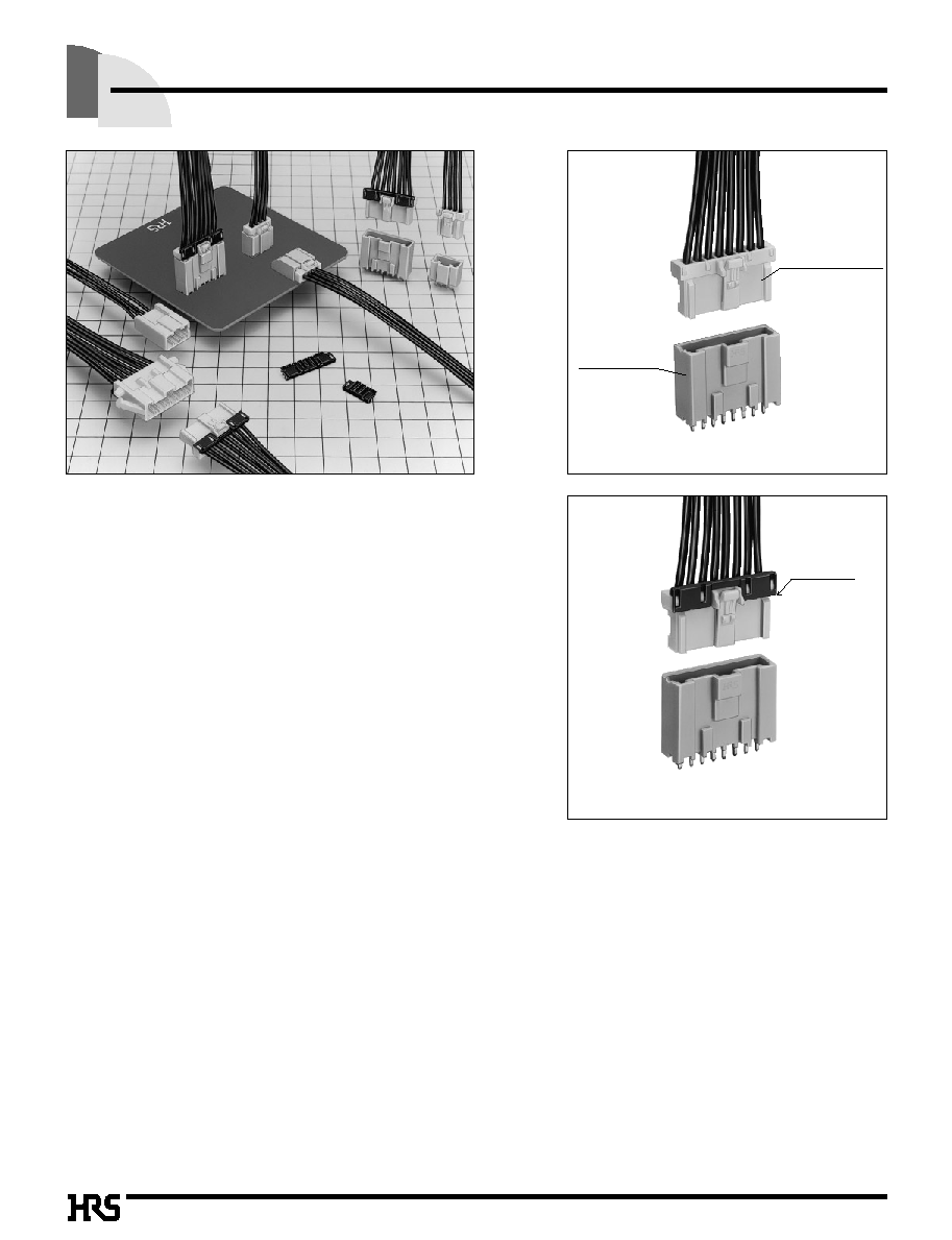
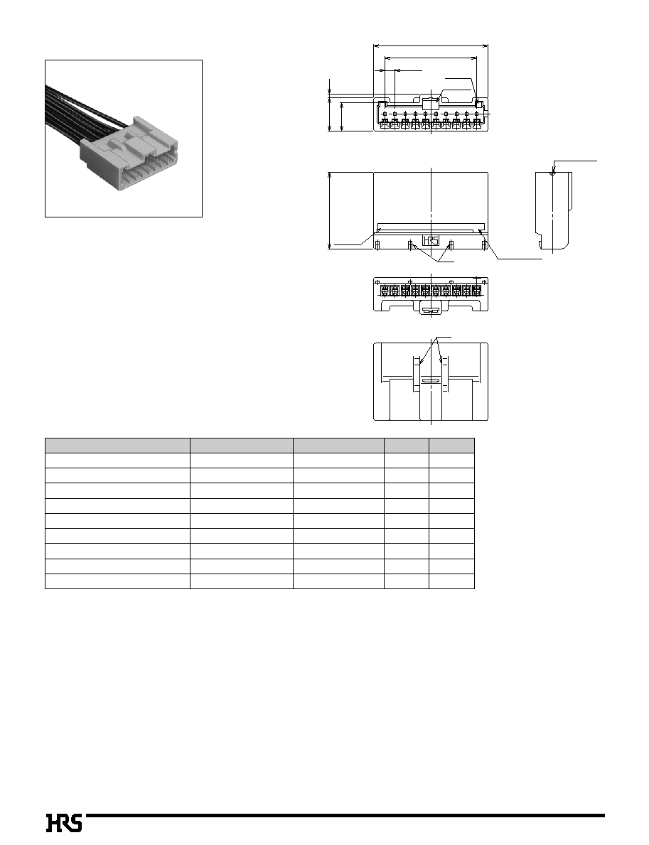
B116
2.5mm Pitch Connector for Full Lock and Discrete Wire Connection
DF1E Series
8. Correspond to Automatic Insertion Machine
The radial tape packaging is provided for 2 to
8 contacts on the straight pin header side, in
order to correspond to mass production.
9. Various Applications
With the same series, various applications can
be used for the board solder dip type and in-
line.
s
Applications
Electronic equipment, office machines,
industrial equipment, and consumer
equipment, and so on
s
Features
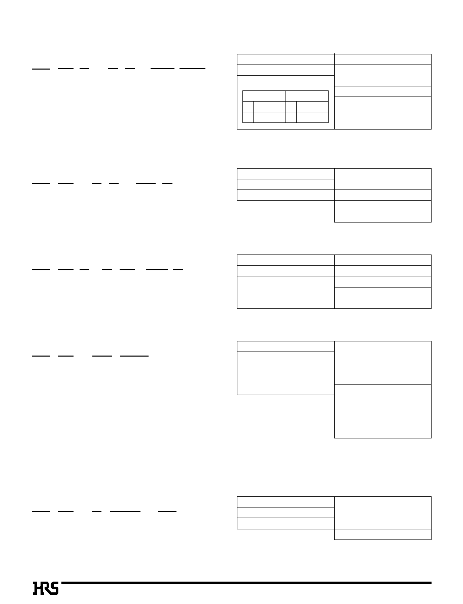
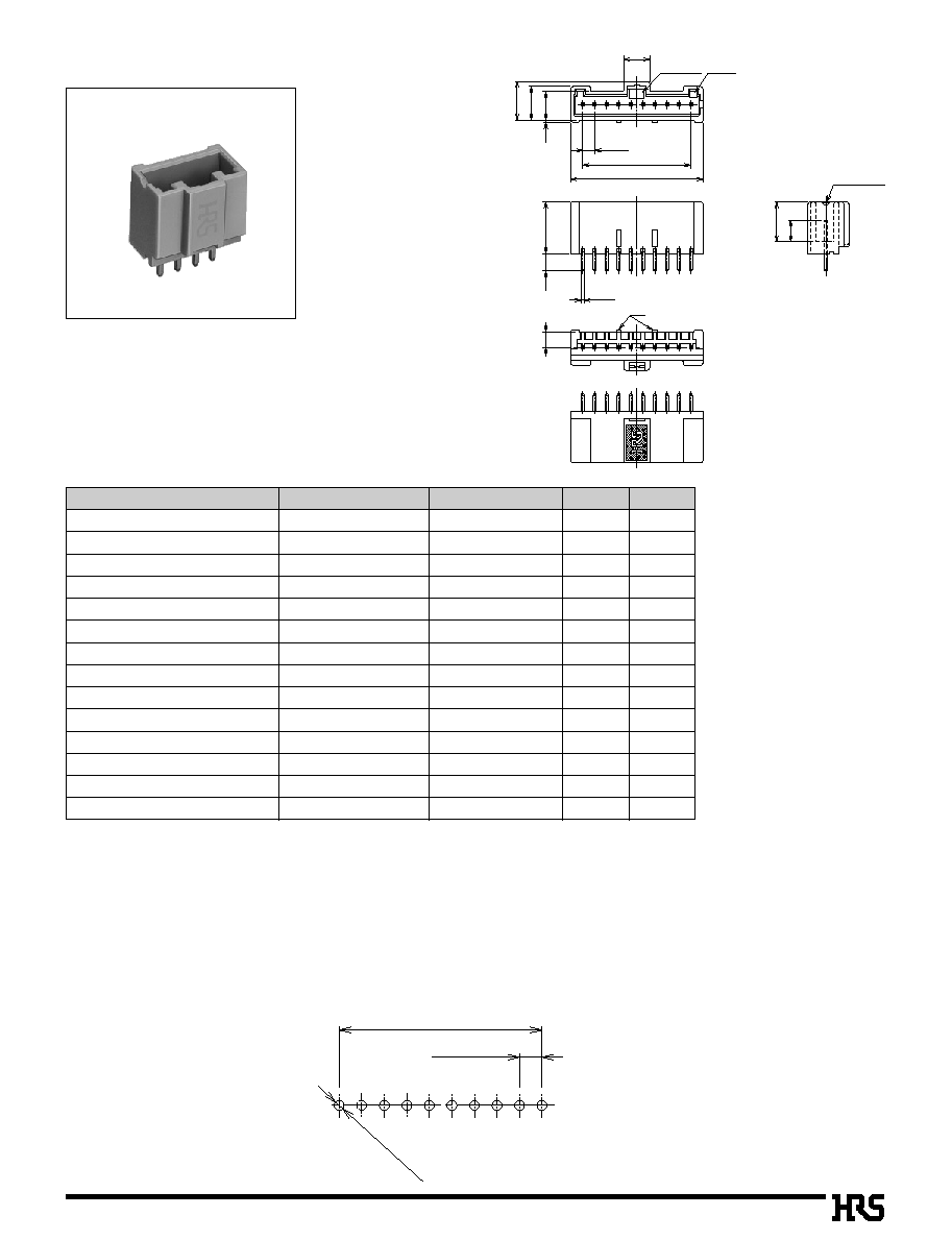
1. Full Lock Function Added
The inner lock system adopts a full lock mechanism.
This mechanism prevents disengagement to occur due to
an unexpected external shock.
2. Increase in Crimping Contact Fixation Force and
Semi-insertion Prevention
The double lock is activated for the use method to give a
stress to the cable, to increase crimping contact fixation
force, and to prevent the semi-insertion of the crimping
contact.
3. Mold Lance Adopted
Since the contact lance may be deformed involving in the
contact after the crimping process, the mold lance has been
adopted.
4. Mis-insertion Prevention
Equipped with the mechanism to completely prevent reverse
insertion and insertion between dissimilar contacts.
5. Means to Prevent Solder Crack
The glass enforcement resin is adopted for the pin header to
prevent a solder crack to occur due to heat compression.
6. Correspond to Potting
Corresponding to potting, the pin header is provided for
product variations.
Corresponding to potting up to 8mm and mounting height
19.8mm (no retainer), the low profile is achieved.
7. Production Facility Cost Reduction
The female crimping contact uses the DF1B series crimping
contact, which has been conventionally marketed.
Investment for new facilities isn't needed. However, if the
retainer is installed in the cable with AWG#22 or more wire,
use the DF1E crimping contact. The female crimping
contact for in-line is used together with the DF1B applicator.
Therefore, no investment is needed for new facilities.
Full lock function
added
Double lock
engaged
Inner-lock system
full lock mechanism
Mis-insertion
prevention
Double lock
engaged

B117
Rating
s
Products Specifications
Current rating Note 1.
AWG
#
20
to
24 :
3A
26 :
2A
28 :
1A
30 :
0.5A
Voltage rating 250VAC
Operating Temperature Range :
-
35
to +
85
Á
Note 2.
Operating Moisture Range :
-
20 to 80%
Storage Temperature Range :
-
10
to +
60
Á
Note 3.
Storage Moisture Range
:
-
40 to 70%
Item
Specification
Condition
1. Contact Resistance
30m
ohms
max.
Measured at 20mV max. and 1mA
2. Insulation Resistance
1000M
ohms
min.
500V DC
3. Withstanding voltage
No flashover or insulation breakdown.
650V AC/1 minute
4. Single Insertor/Extraction Forth
MIN 0.4N, MAX 4.4N
Measured at the square steel pin with 0.635
±
0.002
5. Durability (Mating/un-mating)
30m
ohms
max
30 cycles
6. Vibration
No electrical discontinuity of 1µs or more
Frequency: 10 to 55 Hz, single amplitude of 0.75 mm, 2 hours in each of the 3 directions.
7. Shock
No electrical discontinuity of 1µs or more
Acceleration of 490 m/s
2
, 11 ms duration, sine half-wave waveform, 3 cycles in each of the 3 axis
8.
Humidity (Steady state)
30m
ohms
max
96 hours at temperature of 40Á and humidity of 90% to 95%
9. Temperature Cycle
30m
ohms
max.
(-55
Á
: 30 minutes-> 5 to 35
Á
: 5 minutes-> 85
Á
: 30 minutes-> 5 to 35
Á
: 5 minutes) 5 cicles
10. Resistance to Soldering heat
No deformation of components affecting performance.
Flow: 250
Á
for 10 seconds
Manual soldering: 300
Á
for 3 seconds
Note 1: Includes temperature rise caused by current flow.
Note 2: The term "storage" refers to products stored for long period of time prior to mounting and use. Operating Temperature Range and
Humidity range covers non conducting condition of installed connectors in storage, shipment or during transportation.
Note : The whisker method is implemented for HRS tin plating.
s
Material
Product
Part
Material
Treatment
Remarks
Socket
Insulator
Polyamide
White
UL94V-0
Header
Insulator
Polyamide
Beige
UL94V-0
Contact
Brass
Tin-lead plated
≠≠≠≠≠≠≠
In-line Plug
Insulator
Polyamide
White
UL94V-0
retainer
Insulator
Polyamide
Black
UL94V-0
Crimping contact
Contact
Phosphor copper
Tin plated
≠≠≠≠≠≠≠
Rating
s
C-UL File No.
UL
:E52653
Current rating
Voltage rating
AWG
#
20
to #
22 : 3A
AWG
#
24
to #
28 : 1A
AWG
#
30
: 0.5A
30V AC
C-UL Rating
B118
s
Ordering Information
DF 1E C -
*
P - 2.5 DSA
q
w
r
e
t
y
u
y
q
Pin Header
q
Series Name : DF
w
Series No. : 1E
e
Hold Types
r
Number of Contacts : 2 to 15 contacts
t
Connector Type
P : Pin Header
y
Contact Pitch : 2.5mm
u
Form type
DSA : Straight through hole
DS : Right Angle Type
C
Standard Product
With Boss
Without Boss
G
Potting
With Boss
Without Boss
Note 1 : The right angle pin header has no symbol.
Note 2 : The potting header has 2 to 10 contacts.
Note 1 : When the retainer is used, use DF1E-2022SC(F), DF1B-
2428SC(F), and DF1B-30SC(F) contacts.
Note 1 :
When no retainer is used, all DF1B-
**
SC(F) and DF1E-
2022SC(F) contacts can be used.
DF 1E -
*
S - 2.5 C
q
w
r
e
y
t
q
Socket
q
Series Name : DF
w
Series No. : 1E
e
Number of Contacts : 2 to 15 contacts
r
Connector type
S: Socket
t
Contact Pitch : 2.5mm
y
Form Type
C : Crimping socket
DF 1E -
*
RS
/
P - 2.5
q
w
e
t
r
q
Retainer
q
Series Name : DF
w
Series No. : 1E
e
Number of Contacts : 2 to 10 contacts
r
Connector Type
RS/P : Retainer
Commonly used for socket and in-line plug
t
Contacts Pitch:2.5mm
DF 1E A -
*
EP - 2.5 C
q
w
r
e
u
t
q
In-line Plug
q
Series Name : DF
w
Series No. : 1E
e
In-line Plug type
Blank: With Panel mount Lock
A : Without Panel mount Lock
r
Number of Contacts : 2 to 10 contacts
t
EP : In-line plug
y
Contact Pitch : 2.5mm
u
Form Type
C : Crimping socket
DF 1E -
**
SCF
q
w
e
r
q
Crimping Contact
q
Series Name : DF
w
Series No.
:
Socket side
: 1B (Note 1)
1E (Note 1)
Plug side
: 1E
e
Applicable Cable Size
2022 : AWG
#
20
to #
22
2428 : WG
#
24
to #
28
30
: AWG
#
30
r
Packaging Type
SCF : Female contact : Reel
SF
: Female contact : Bag
PCF : Male contact : Reel
PC
: Male contact : Bag

B119
s
Application Pattern
Pin Header
q
Straight Type
q
Right Angle Type
In-line Plug
q
In-line Plug (Panel Mount Lock Type)
Photo: Contact Inserted
q
In-line Plug
Photo: Contact Inserted
Retainer
Socket
Photo : Contact Inserted
q
Straight Potting Type

B120
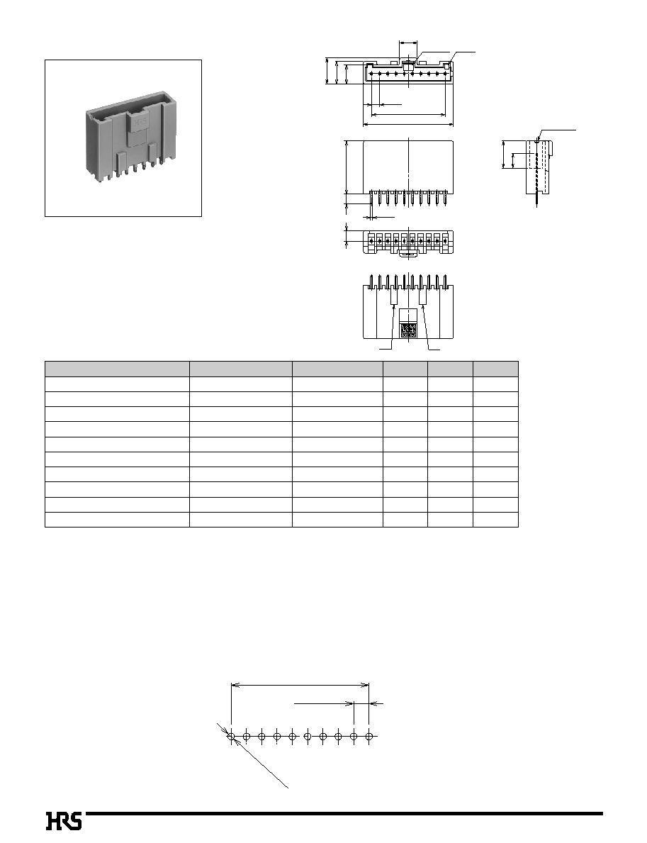
s
Right Angle Pin Header
B
PCB mounting pattern (Board Thickness t = 1.6
±
0.1)
The symbol
**
included in
HRS No. and the product spec
No. indicates the Specific No.
Note 1. : A packaging quantity is delivered by the bag unit (100 pcs.). If needed, please order the products per bag. However, the quantity
for delivery will be changed according to the Specific No.
Note 2. : The 2 to 4 contacts differ in two convex portions from those in above figures. The 2 and 3 contacts are not contained, but the 4
contact connector is contained in the center at one point.
Note 3. : Styles of 2 to 4 contact connectors partially differ from those in above figures.
Part Number
Number of Contacts
A
B
CL No.
P = 2.5±0.05
A±0.1
* ≠
ÿ1.1
+0.1
0
Contact No. mark
5.4
P = 2.5
A
B
Mold Cavity
No. mark
3.2
5.9
0.5
6.95
8
10.8
13.8
4.5
8.3
2.9
M 0.64
Note 2
Contact No.1 indicated
10
A
DF1E ≠
0
2P≠2.5DS(**)
DF1E ≠
0
3P≠2.5DS(**)
DF1E ≠
0
4P≠2.5DS(**)
DF1E ≠
0
5P≠2.5DS(**)
DF1E ≠
0
6P≠2.5DS(**)
DF1E ≠
0
7P≠2.5DS(**)
DF1E ≠
0
8P≠2.5DS(**)
DF1E ≠
0
9P≠2.5DS(**)
DF1E ≠10P≠2.5DS(**)
DF1E ≠11P≠2.5DS(**)
DF1E ≠12P≠2.5DS(**)
DF1E ≠13P≠2.5DS(**)
DF1E ≠14P≠2.5DS(**)
DF1E ≠15P≠2.5DS(**)
541 ≠ 0985≠ 0 ≠**
541 ≠ 0986≠ 3 ≠**
541 ≠ 0987≠ 6 ≠**
541 ≠ 0988≠ 9 ≠**
541 ≠ 0989≠ 1 ≠**
541 ≠ 0990≠ 0 ≠**
541 ≠ 0991≠ 3 ≠**
541 ≠ 0992≠ 6 ≠**
541 ≠ 0993≠ 9 ≠**
541 ≠ 0994≠ 1 ≠**
541 ≠ 0995≠ 4 ≠**
541 ≠ 0996≠ 7 ≠**
541 ≠ 0997≠ 0 ≠**
541 ≠ 0998≠ 2 ≠**
2
3
4
5
6
7
8
9
10
11
12
13
14
15
0
2.5
0
5.0
0
7.5
10.0
12.5
15.0
17.5
20.0
22.5
25.0
27.5
30.0
32.5
35.0
0
7.5
10.0
12.5
15.0
17.5
20.0
22.5
25.0
27.5
30.0
32.5
35.0
37.5
40.0
B121
s
Straight Pin Header
B
PCB mounting pattern (Board Thickness t = 1.6
±
0.1)
The symbol
**
included in
HRS No. and the product spec
No. indicates the Specific No.
Note 1. : A packaging quantity is delivered by the bag unit (100 pcs.). If needed, please order the products per bag. However, the quantity
for delivery will be changed according to the Specific No.
Note 2. : The 2 to 4 contacts differ in two convex portions from those in above figures. The 2 and 3 contacts are not contained, but the 2
and 3 contacts are not contained, and 4 contact is in the center at one point.
Note 3. : Styles of 2 to 4 contacts partially differ from those in above figures.
Note 4. : The radial package is prepared for DF1EC-
*
P-2.5DSA(25).However, 2 to 8 contacts only are provided. (Quantity of packaged 2
and 3 contacts: 1000pcs., 4 to 8 contacts: 400pcs.)
Part Number
Number of Contacts
A
B
CL No.
P = 2.5±0.05
A±0.1
* ≠
ÿ1.1
+0.1
0
8.3
4.5
0.5
6.95
8
Contact No.1 indicated
Note 2
5.9
Contact No. mark
5.4
P = 2.5
A
B
Mold Cavity
No. mark
3.6
M 0.64
10.8
3.2
10
A
DF1EC≠
0
2P≠2.5DSA(**)
DF1EC≠
0
3P≠2.5DSA(**)
DF1EC≠
0
4P≠2.5DSA(**)
DF1EC≠
0
5P≠2.5DSA(**)
DF1EC≠
0
6P≠2.5DSA(**)
DF1EC≠
0
7P≠2.5DSA(**)
DF1EC≠
0
8P≠2.5DSA(**)
DF1EC≠
0
9P≠2.5DSA(**)
DF1EC≠10P≠2.5DSA(**)
DF1EC≠11P≠2.5DSA(**)
DF1EC≠12P≠2.5DSA(**)
DF1EC≠13P≠2.5DSA(**)
DF1EC≠14P≠2.5DSA(**)
DF1EC≠15P≠2.5DSA(**)
541≠ 0867≠ 4 ≠**
541≠ 0868≠ 7 ≠**
541≠ 0869≠ 0 ≠**
541≠ 0870≠ 9 ≠**
541≠ 0871≠ 1 ≠**
541≠ 0872≠ 4 ≠**
541≠ 0873≠ 7 ≠**
541≠ 0874≠ 0 ≠**
541≠ 0875≠ 2 ≠**
541≠ 0876≠ 5 ≠**
541≠ 0877≠ 8 ≠**
541≠ 0878≠ 0 ≠**
541≠ 0879≠ 3 ≠**
541≠ 0880≠ 2 ≠**
2
3
4
5
6
7
8
9
10
11
12
13
14
15
0
2.5
0
5.0
0
7.5
10.0
12.5
15.0
17.5
20.0
22.5
25.0
27.5
30.0
32.5
35.0
0
7.5
10.0
12.5
15.0
17.5
20.0
22.5
25.0
27.5
30.0
32.5
35.0
37.5
40.0
B122
s
Straight Pin Header for Potting
B
PCB mounting pattern (Board Thickness t = 1.6
±
0.1)
The symbol
**
included in HRS No.
and the product
spec No. indicates
the Specific No.
Note 1. : A packaging quantity is delivered by the bag unit (100 pcs.). If needed, please order the product per bag. However, the quantity
for delivery will be changed according to spec number.
Note 2. : The 2 to 6 and 9 to 10 contact connectors differ in two convex portions from those in above figures. The 2 to 5 and 9 to 10
contacts are not contained, but the 6 contact is bonded to the convex portion at both ends.
Note 3. : Styles of 2 to 4 contact may partially differ from the above figures.
Note 4. : The radial tape packaging is prepared for DF1EG-
*
P-2.5DSA(25).However, 2 to 8 contacts are available. (Quantity of packaged 2
and 3 contacts : 1000pcs., 4 to 8 contacts: 400pcs.)
Part Number
Number of Contacts
A
B
C
CL No.
P = 2.5±0.05
A±0.1
* ≠
ÿ1.1
+0.1
0
6.95
C
4.5
8.3
Note 2
5.9
Contact No. mark
5.4
P=
2.5
A
B
Mold Cavity
No. mark
3
M
0.64
16.3
Contact No.1 indicated
Note 2
3.2
10
A
DF1EG ≠
0
2P≠2.5DSA(**)
DF1EG ≠
0
3P≠2.5DSA(**)
DF1EG ≠
0
4P≠2.5DSA(**)
DF1EG ≠
0
5P≠2.5DSA(**)
DF1EG ≠
0
6P≠2.5DSA(**)
DF1EG ≠
0
7P≠2.5DSA(**)
DF1EG ≠
0
8P≠2.5DSA(**)
DF1EG ≠
0
9P≠2.5DSA(**)
DF1EG ≠10P≠2.5DSA(**)
DF1EG ≠11P≠2.5DSA(**)
541 ≠ 0923 ≠ 3**
541 ≠ 0924 ≠ 6**
541 ≠ 0925 ≠ 9**
541 ≠ 0926 ≠ 1**
541 ≠ 0927 ≠ 4**
541 ≠ 0928 ≠ 7**
541 ≠ 0929 ≠ 0**
541 ≠ 0930 ≠ 9**
541 ≠ 0931 ≠ 1**
541 ≠ 0932 ≠ 4**
2
3
4
5
6
7
8
9
10
11
0
2.5
0
5.0
0
7.5
10.0
12.5
15.0
17.5
20.0
22.5
25.0
0
7.5
10.0
12.5
15.0
17.5
20.0
22.5
25.0
27.5
30.0
7.8
7.8
7.8
8.0
8.0
8.0
8.0
8.0
8.0
8.0

B123
4.2±0.05
8.4
+0.1
0
1.1
5.8
D
( E +
3.5
+0.1
0
Panel
Note 4
+0.1
0
+0.1
0
+0.2
0
+0.1
0
s
In-line Plug (Panel Mount Lock Type)
B
Panel Cutout
The symbol
**
included in HRS No. and the product spec No. indicates the Specific No.
Note 1. : A packaging quantity is delivered by the bag unit (100 pcs.). If needed, please order the products per bag. However, the quantity
for delivery will be changed according to the Specific No.
Note 2. : In regard to 2 to 5 contacts, the retainer fixed convex portions are located at both ends.
Note 3. In regard to 2 to 7 contacts, 2 convex portions are different from those in the above figures.
Note 4. Use the no radius side at the panel edge in the looking area.
Note 5. : Panel fixation is loosened. (May be enlarged according to the panel board thickness.)
Note 6. : Styles of 2 to 4 contact partially differ from those in the above figures.
*
Refer to page B122 for the retainer.
Part Number
Number of Contacts
A
B
C
D
E
CL No.
Note 3
Note 2
3
5
7
9
10
1
P = 2.5
B
A
2.8
2.8
8.1
6.9
18.8
12
C
0.9
Contact No.1 indicated
Contact No.1 indicated
Contact No. indicated
Contact No. mark
Mold Cavity
No. mark
A
1 0
DF1E≠
0
2EP≠2.5C(**)
DF1E≠
0
3EP≠2.5C(**)
DF1E≠
0
4EP≠2.5C(**)
DF1E≠
0
5EP≠2.5C(**)
DF1E≠
0
6EP≠2.5C(**)
DF1E≠
0
7EP≠2.5C(**)
DF1E≠
0
8EP≠2.5C(**)
DF1E≠
0
9EP≠2.5C(**)
DF1E≠10EP≠2.5C(**)
541≠ 0943≠ 0 ≠**
541≠ 0944≠ 3 ≠**
541≠ 0945≠ 6 ≠**
541≠ 0946≠ 9 ≠**
541≠ 0947≠ 1 ≠**
541≠ 0948≠ 4 ≠**
541≠ 0949≠ 7 ≠**
541≠ 0950≠ 6 ≠**
541≠ 0951≠ 9 ≠**
2
3
4
5
6
7
8
9
10
8.0
10.5
13.0
15.5
18.0
20.5
23.0
25.5
28.0
2.5
5.0
7.5
10.0
12.5
15.0
17.5
20.0
22.5
15.0
17.5
20.0
22.5
25.0
27.5
30.0
32.5
35.0
8.4
10.9
13.4
15.9
18.4
20.9
23.4
25.9
28.4
Photo: Contact Inserted.
1.7 to 2.0
1.3 to 1.6
0.9 to 1.2
0.7 to 0.8
Panel Thickness
1.5
1.0
0.5
0.0
X
11.9
14.4
16.9
19.4
21.9
24.4
26.9
29.4
31.9
B124
s
In-line Plug
The symbol
**
included in
HRS No. and the product spec
No. indicate a Specific No.
Note 1. : A packaging quantity is delivered by the bag unit (100 pcs.). If needed, please order the products per bag. However, the quantity
for delivery will be changed according to the Specific No.
Note 2. : In regard to 2 to 5 contacts, the retainer fixed convex portions are located at both ends.
Note 3. : 2 to 7 contacts do not contain two convex portions, which is different from the above figure.
Note 4. : Styles of 2 to 4 contacts partially differ from the above figures.
*
Refer to page B122 for retainer.
Part Number
Number of Contacts
A
B
CL No.
Note 3
Note 2
3
5
7
9
1 0
1
P = 2.5
B
A
8.1
6.9
18.8
0.9
Contact No.1 indicated
Contact No.1 indicated
Contact No. mark
Contact No. mark
Mold Cavity
No. mark
A
1 0
DF1EA ≠
0
2EP≠2.5C(**)
DF1EA ≠
0
3EP≠2.5C(**)
DF1EA ≠
0
4EP≠2.5C(**)
DF1EA ≠
0
5EP≠2.5C(**)
DF1EA ≠
0
6EP≠2.5C(**)
DF1EA ≠
0
7EP≠2.5C(**)
DF1EA ≠
0
8EP≠2.5C(**)
DF1EA ≠
0
9EP≠2.5C(**)
DF1EA ≠10EP≠2.5C(**)
541 ≠ 0957 ≠ 5 ≠ **
541 ≠ 0958 ≠ 8 ≠ **
541 ≠ 0959 ≠ 0 ≠ **
541 ≠ 0960 ≠ 0 ≠ **
541 ≠ 0961 ≠ 2 ≠ **
541 ≠ 0962 ≠ 5 ≠ **
541 ≠ 0963 ≠ 8 ≠ **
541 ≠ 0964 ≠ 0 ≠ **
541 ≠ 0965 ≠ 3 ≠ **
2
3
4
5
6
7
8
9
10
0
8.0
10.5
13.0
15.5
18.0
20.5
23.0
25.5
28.0
0
2.5
0
5.0
0
7.5
10.0
12.5
15.0
17.5
20.0
22.5
Photo: Contact Inserted

B125
s
Socket
The symbol
**
included in HRS No.
and the product
spec No. indicate a
Specific No.
Note 1. : A packaging quantity is delivered by the bag unit (100 pcs.). If needed, please order the products per bag. However, the quantity
for delivery will be changed according to spec number.
Note 2. : The 2 contact connector is equipped with the convex portion to prevent false-insertion.
Note 3. : The 2 consult Has no wall on the locking side
Note 4. : The 2 to 5 contacts contain the retainer fixed convex portions at both ends.
*
Refer to page B122 for the retainer.
Part Number
Number of Contacts
A
B
C
CL No.
7.55
No. 1 contact indicated
Contact No. mark
Note 4
Mold Cavity
No. mark
P = 2.5
A
4.55
C
B
8.5
11.8
Note 3
Note 3
Note 4
Note 2
A
10
1
DF1E ≠
0
2S≠2.5C(**)
DF1E ≠
0
3S≠2.5C(**)
DF1E ≠
0
4S≠2.5C(**)
DF1E ≠
0
5S≠2.5C(**)
DF1E ≠
0
6S≠2.5C(**)
DF1E ≠
0
7S≠2.5C(**)
DF1E ≠
0
8S≠2.5C(**)
DF1E ≠
0
9S≠2.5C(**)
DF1E ≠10S≠2.5C(**)
DF1E ≠11S≠2.5C(**)
DF1E ≠12S≠2.5C(**)
DF1E ≠13S≠2.5C(**)
DF1E ≠14S≠2.5C(**)
DF1E ≠15S≠2.5C(**)
541 ≠ 0811 ≠ 0 ≠ **
541 ≠ 0812 ≠ 2 ≠ **
541 ≠ 0813 ≠ 5 ≠ **
541 ≠ 0814 ≠ 8 ≠ **
541 ≠ 0815 ≠ 0 ≠ **
541 ≠ 0816 ≠ 3 ≠ **
541 ≠ 0817 ≠ 6 ≠ **
541 ≠ 0818 ≠ 9 ≠ **
541 ≠ 0819 ≠ 1 ≠ **
541 ≠ 0820 ≠ 0 ≠ **
541 ≠ 0821 ≠ 3 ≠ **
541 ≠ 0822 ≠ 6 ≠ **
541 ≠ 0823 ≠ 9 ≠ **
541 ≠ 0824 ≠ 1 ≠ **
2
3
4
5
6
7
8
9
10
11
12
13
14
15
0
2.5
0
5.0
0
7.5
10.0
12.5
15.0
17.5
20.0
22.5
25.0
27.5
30.0
32.5
35.0
0
8.0
10.5
13.0
15.5
18.0
20.5
23.0
25.5
28.0
30.5
33.0
35.5
38.0
40.5
0
5.4
0
7.9
10.4
12.9
15.4
17.9
20.4
22.9
25.4
27.9
30.4
32.9
35.4
37.9
Photo: Contact Inserted

B126
s
Retainer
The symbol
**
included in
HRS No. and the product spec
No. indicates the Specific No.
Note 1. : A packaging quantity is delivered by the bag unit (100 pcs.). If needed, please order the products per bag. However, the quantity
for delivery will be changed according to spec number.
Note 2. : The 2 to 4 contacts contain socket and plug fixed holes at both ends.
*
This retainer can be used together with the socket and relay plug.
Part Number
Number of Contacts
A
B
CL No.
Mold Cavity
No. mark
Contact No. mark
1.9
A
P = 2.5
B
1.5
5.9
3.3
0.7
1.7
Note2
Note2
1 0
A
DF1E ≠
0
2RS/P≠2.5(**)
DF1E ≠
0
3RS/P≠2.5(**)
DF1E ≠
0
4RS/P≠2.5(**)
DF1E ≠
0
5RS/P≠2.5(**)
DF1E ≠
0
6RS/P≠2.5(**)
DF1E ≠
0
7RS/P≠2.5(**)
DF1E ≠
0
8RS/P≠2.5(**)
DF1E ≠
0
9RS/P≠2.5(**)
DF1E ≠10RS/P≠2.5(**)
541 ≠ 0971 ≠ 6
541 ≠ 0972 ≠ 9
541 ≠ 0973 ≠ 1
541 ≠ 0974 ≠ 4
541 ≠ 0975 ≠ 7
541 ≠ 0976 ≠ 0
541 ≠ 0977 ≠ 2
541 ≠ 0978 ≠ 5
541 ≠ 0979 ≠ 8
2
3
4
5
6
7
8
9
10
0
8.0
10.5
13.0
15.5
18.0
20.5
23.0
25.5
28.0
0
2.5
0
5.0
0
7.5
10.0
12.5
15.0
17.5
20.0
22.5

B127
s
Plug Crimping Contact
Part Number
DF1E ≠ 2022PCF
DF1E ≠ 2022PC
DF1E ≠ 2428PCF
DF1E ≠ 2428PC
DF1E ≠ 30PCF
DF1E ≠ 30PC
541 ≠ 0937 ≠ 8
541 ≠ 0938 ≠ 0
541 ≠ 0939 ≠ 3
541 ≠ 0940 ≠ 2
541 ≠ 0941 ≠ 5
541 ≠ 0942 ≠ 8
20
22
24
28
30
AWG # 20
AWG # 22
AWG # 24
AWG # 28
AWG # 30
1.2 to 1.9mm
0.9 to 1.5mm
0.6 to 1.2mm
Reel
Bag
Reel
Bag
Reel
Bag
10,000
100
10,000
100
10,000
100
Applicable
Cable Indication
Applicable Cable
AWG
Jacket Diameter
CL No.
Packaging
Type
Quantity
q
Crimping Contact Extraction Tool DF-C-PO(B)
AWG # 20 (21 cores./0.18mm)
AWG # 22 (17 cores./0.16mm)
AWG # 24 (11 cores./0.16mm)
AWG # 26 (
0
7 cores./0.16mm)
AWG # 28 (
0
7 cores./0.127mm)
AWG # 30 (
0
7 cores./0.1mm)
Conductor Size (Wire construction)
q
Applicable Cable (Tin plating annealed copper wire)
q
Recommended Cable
UL1061, UL1007
q
Strip Length
3.0 to 3.7mm
Note : If other cables are used instead of the applicable
cable, contact Hirose sales department.
6.5
14.9
2.2
1.2
0.8
2.2
0.64
0.64
1.5
19.9

B128
s
Socket Crimping Contact
Part Number
DF1E
≠
2022SCF
DF1E
≠
2022SC
DF1B
≠
2022SCF
DF1B
≠
2022SC
DF1B
≠
2428SCF
DF1B
≠
2428SC
DF1B
≠
30SCF
DF1B
≠
30SC
541 ≠ 0999 ≠ 5
541 ≠ 1000 ≠ 2
541 ≠ 0223 ≠ 1
541 ≠ 0224 ≠ 4
541 ≠ 0678 ≠ 1
541 ≠ 0679 ≠ 4
541 ≠ 0682 ≠ 9
541 ≠ 0683 ≠ 1
20
22
20
22
24
28
30
AWG # 20
AWG # 22
AWG # 20
AWG # 22
AWG # 24
AWG # 28
AWG # 30
1.2 to 1.9mm
1.2 to 1.9mm
0.9 to 1.5mm
0.6 to 1.2mm
Reel
Bag
Reel
Bag
Reel
Bag
Reel
Bag
10,000
100
10,000
100
10,000
100
10,000
100
Applicable
Cable Indication
Applicable Cable
AWG
Jacket Diameter
CL No.
Packaging
Type
Quantity
q
Crimping Contact Extraction Tool DF-C-PO(B)
AWG # 20 (21 cores./0.18mm)
AWG # 22 (17 cores./0.16mm)
AWG # 24 (11 cores./0.16mm)
AWG # 26 (
0
7 cores./0.16mm)
AWG # 28 (
0
7 cores./0.127mm)
AWG # 30 (
0
7 cores./0.1mm)
Conductor Size (Wire construction)
q
Applicable Cable (Tin plating annealed copper wire)
q
Recommended Cable
UL1061, UL1007
q
Strip Length
2.0mm to 2.5mm
Note : If other cables are used instead of the applicable
cable, consult Hirose sales department.
q
DF1E-2022SCF
q
DF1B
- * * * *
SCF
1.6
1.95
Applicable cable indicated
1.95
2.55
3.35
12.9
9.4
1.4
0.83
1.75
0.55
1.4
14
6.1
2.5
9.5
1
1.6
0.975
1.75
Applicable cable indicated
1.4
2.4

B129
B
Crimping Tools
Part Number
AP105
≠
DF1E
≠
2022S
AP105
≠
DF1B
≠
2022S
K
K
AP105
≠
DF1B
≠
2428S
K
K
AP105
≠
DF1B
≠
30S
K
K
AP105
≠
DF1B
≠
2022P
K
K
AP105
≠
DF1B
≠
2428P
K
K
AP105
≠
DF1B
≠
30P
K
K
CM
≠
105
K
K
HT102/DF1E
≠
2022S
DF1B
≠
TA2022SHC
K
K
DF1B
≠
TA2428SHC
K
K
DF1B
≠
TA30SHC
K
K
HT102/DF1BE
≠
2022P
HT102/DF1BE
≠
2428P
HT102/DF1BE
≠
30P
DF ≠ C ≠ PO (B)
901
≠
4561
≠
0
901
≠
4510
≠
9
901
≠
4518
≠
0
901
≠
4517
≠
8
901
≠
4509
≠
0
901
≠
4521
≠
5
901
≠
4519
≠
3
901
≠
0005
≠
4
550
≠
0277
≠
1
550
≠
0182
≠
7
550
≠
0209
≠
1
550
≠
0211
≠
3
550
≠
0278
≠
4
550
≠
0279
≠
7
550
≠
0280
≠
6
550
≠
0179
≠
2
DF1E ≠ 2022SCF
DF1B ≠ 2022SCF
DF1B ≠ 2428SCF
DF1B ≠ 30SCF
DF1E ≠ 2022PCF
DF1E ≠ 2428PCF
DF1E ≠ 30PCF
≠≠≠≠≠≠
DF1E ≠ 2022SC
DF1B ≠ 2022SC
DF1B ≠ 2428SC
DF1B ≠ 30SC
DF1E ≠ 2022PC
DF1E ≠ 2428PC
DF1E ≠ 30PCF
DF1E ≠ 2022SC (F)
DF1B ≠ * * * * SC (F)
DF1E ≠ * * * * PC (F)
CL No.
Applicable Contact
Item
Applicator
Main Press Unit
Manual Crimping Tool
Contact Extraction Tool
Note 1. : Add "
K
K
" to the last number of the product, in order to use DF1B series tools, which have been conventionally merchandized.
Note 2. : f any trouble has occurred due to other tools, which are not designated by Hirose, Hirose won't guarantee any products.
B130
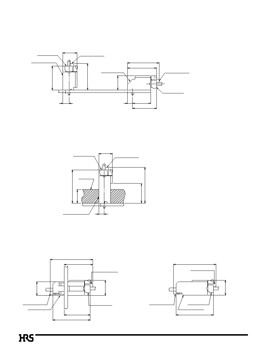
B
Application Pattern
q
Standard Header
q
Header for Potting
q
Panel Mounting Lock In-line Plug
q
In-line Plug
3.7
DF1E _
*
S _ 2.5 C
DF1E# _
*
P _ 2.5 DSA
DF1E _
*
RS / P _ 2.5
DF1E _
*
S _ 2.5 C
DF1E _
*
P _ 2.5 DS
DF1E _
*
RS / P _ 2.5
18.8
17.3
10.8
3
14.3
8.5
8.5
14.3
15.8
8
3.2
8
M A X
Potting Resin
DF1E _
*
S _ 2.5 C
DF1E _
*
RS / P _ 2.5
DF1E# _
*
P _ 2.5 DSA
11.7
21.3
19.8
8.1
DF1E _
*
RS / P _ 2.5
DF1E _
*
S _ 2.5 C
DF1E _
*
EP _ 2.5 C
DF1E _
*
RS / P _ 2.5
25.3
22.3
17
15.5
9
DF1E _
*
RS / P _ 2.5
DF1E _
*
S _ 2.5 C
DF1EA _
*
EP _ 2.5 C
DF1E _
*
RS / P _ 2.5
25.3
9
22.3
Panel

B131
B
Precautions
1. Recommended Soldering Condition
:
Flow: 250Á for 3 seconds
Manual soldering: 290Á for 2 seconds
2. Cleaning Condition
: Refer to Nylon Connector Use Hand book.
However, if the connector is cleaned by the potting header, the detergent remains
within the connector, which will cause malfunction.
3. Connection Condition
: Refer to Nylon Connector Use Hand book.
4. Cautions
:
q
To remove the connector, if the connector is forcedly removed, it will cause
connector damage. If the connector is hardly removed, slightly push the connector
once, and then remove it using the lock.
q
In some method for laying the cable within equipment, a tension may be applied to
the cable so as to remove the contact. In this case, it is recommended to use the
retainer.
q
If the potting process is implemented, it is desirable to fill the connector with resin,
considering the resin surface tensile force.
q
The color phase of this product may be slightly different from that of the forming
product according to the manufacturing lot and future storage conditions, however
the difference doesn't affect the performance.