
1
NEW
2002.5
DF20A-**DS-1C
Socket
DF20F(G)-**DP-1V
Pin Header
DF20F-****SCFA
Contact
1
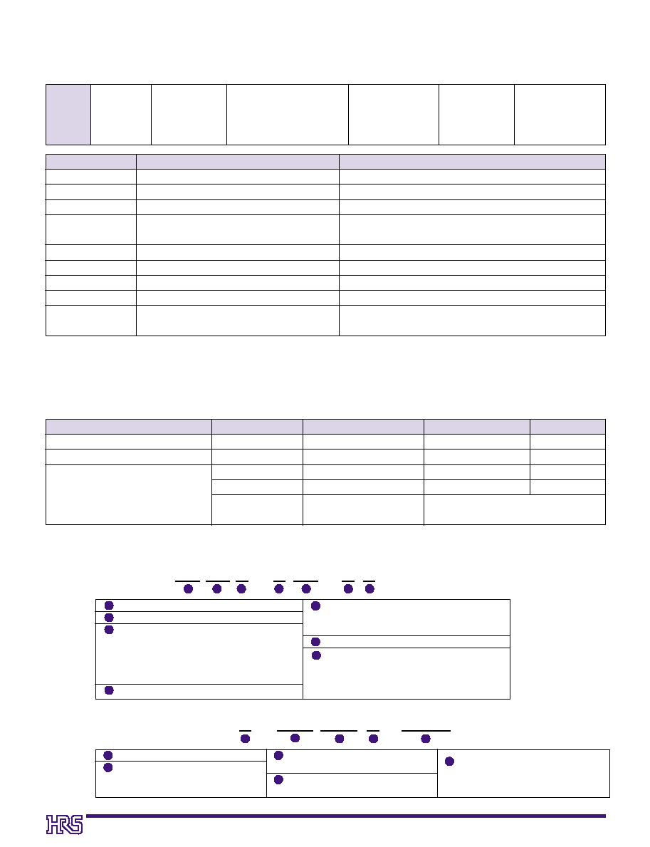
Narrower external width and length
Metal fitting
s
Features
1. Contact Pitch
1 mm contact pitch allows reliable solder and cable
termination.
2. Low profile
Total mating height above the board is 5.8 mm for the
straight type and 5.5 mm for the right angle type.
3. Reliable electrical connection wipe
Effective electrical connection is assured with a 1mm wipe of
mating contacts.
4. Narrower external width and length
Redesigned metal fittings decreased the overall length of the
board- mount receptacle and permit end-to-end mounting of
several connectors.
5. Automatic equipment board placement
Straight type pin headers are supplied with a 5.4 mm X 4.6mm
flat platform to allow vacuum pick-up and placement on the
board.
6. Product variations
(1) Available with 10, 20, 30, 40, and 50 contacts.
(2) Pin headers are available in two types: with or without
board positioning bosses.
(3) Depending on specific application pin headers can be
ordered in straight or right angle types.
s
Applications
Notebook PC, small office automation equipment, small
consumer devices, portable devices.
Any application requiring low profile reliable board-to-cable
connection with a AWG #28, AWG#30, AWG#32 conductors.
1mm Pitch, Double Rows
1 mm Pitch Double Rows Low Profile Board-to-Cable Connectors
DF20 series
6.2
5.5
DF20F
**DP-1H
DF20A-
**DS-1C
Cable
Socket
PCB
Cable
PCB
5.4
Socket
DF20A-
**DS-1C
Pin
Header
Pin
Header
5.8
DF20F(G)-
**DP-1V
2
2
s
Product Specifications
Rating
Rated current
Rated voltage
AWG#28 : 1A
AWG#30 : 0.9A
AWG#32 : 0.7A
100V AC
Operating temperature range
Operating humidity range
Storage temperature range
Storage humidity range
-35∞C to 85∞C (Note 1,2)
-
20% to 80%
-10∞C to 60∞C (Note 2)
-
40% to 70%
Measured at 100V DC
Conduction of 300V AC applied for 1 minute
Measure at 100mA.
Measured with a steel pin of 0.2 ±0.005 thickness
Frequency of 10 to 55 Hz, single amplitude of 0.75 mm, in 3 directions for 2hours
Temperature of 40
±
2
Á
, humidity of 90% to 95%, left standing for 96 hours
(-55
Á
:30min
/
5
Á
to 35
Á
: 2 to 3min
/
85
Á
:30min
/
5
Á
to 35
Á
:2 to 3min ) for 5 cycles
50 cycles
Reflow: At the recommended temperature profile, manual
solder: Soldering iron temperature of 300∞C for 3 seconds
500M
¯
min.
No flashover or insulation breakdown
30
m
¯
max.
Min. 0.2 N (20 gf), Max. 2 N (200 gf)
No electrical discontinuity of 1µs min.
Contact resistance of 30m
¯
max., insulation resistance of 100M
¯
min.
Contact resistance of 30m
¯
max,insulation resistance of 500M
¯
min.
Contact resistance of 30m
¯ max.
No deformation of the insulator parts that will
affect performance
1.Insulation resistance
2.Withstanding voltage
3.Contact resistance
4.Insertion-Extraction force
4.
(per contact)
5.Vibration
6.Humidity
7.Temperature cycle
8.Mechanical operation
9.Resistance to
Soldering heat
Item
Specifications
Conditions
Note1: Includes temperature rise caused by current flow.
Note2: The term "storage" refers to products stored for long periods of time prior to mounting and use.
Note2:
Operating temperature range and Humidity range covers non-conducting conditions of installed connectors in storage,
Note2:
shipment or transportation.
s
Materials
Remarks
UL94V-0
----------
UL94V-0
----------
Item
Part
Material
Finish
Socket
Socket contact
Pin header
Insulator
Contact
Insulator
Contact
Metal Fitting
Polyamide
Phosphor bronze
Polyamide
Phosphor bronze
Brass
Color : Beige
Gold plating
Color : Beige
Gold plating
V type: Solder plating
H type: Tin-Copper plating (Pb free)
s
Ordering Information
DF 20 # -
*
DS - 1 C
1
4
6
2
3
5
7
Series name : DF
Boss Type
s
Pin header
s
F: Without boss
s
G: With boss
s
Crimp socket: A
1
Number of contacts: 10, 20, 30, 40, 50
2
3
4
5
Series No.
: 20
6
Connector type
DS: Double-row socket
DP: Double-row pin header
Contact pitch: 1 mm
Type of housing, header
C: Crimp housing
V: Straight SMT header
H: Right angle SMT header
q
Connectors
q
Contacts
7
7
F
Applicable wire size
2830: AWG #28 to 30
3032: AWG #30 to 32
Contact & packaging type
SCF: Socket contact reel
Plating type
A: Gold plating
Packaging Specifications
Blank: 1 reel = 10,000 pieces
41: 1 reel = 20,000 pieces
DF20 F - 2830 SCF A (
* *
)
1
1
4
4
2
2
3
3
5
5
3
s
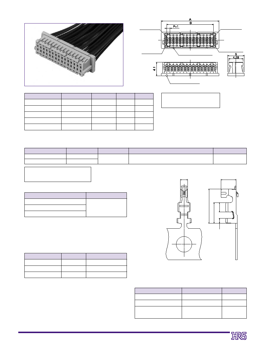
Double Row Socket
s
Socket Crimp Contacts
CL No.
Product No.
Number of Contacts
A
B
686-0020-3
686-0021-6
686-0022-9
686-0023-1
686-0024-4
DF20A-10DS-1C
DF20A-20DS-1C
DF20A-30DS-1C
DF20A-40DS-1C
DF20A-50DS-1C
10
20
30
40
50
1
7.2
12.2
17.2
22.2
27.2
1
4.0
1
9.0
14.0
19.0
24.0
[Specifications number]-*, (**)
(59): Gold plating, embossed tape
packaging
[Specifications number] -*, (**)
Blank 1 reel
: 10,000 pieces
41 1 reel
: 20,000 pieces
CL No.
Product No.
Type of contacts
Quantity
Plating type
686-0042-6-
**
686-0043-9-
**
DF20F-2830SCFA(
**
)
DF20F-3032SCFA(
**
)
Reel contacts
See specifications number column
Gold plating
Applicable Wire Size (Stranded wire conductor)
Jacket diameter
AWG #28 (7/0.127 mm)
AWG #30 (7/0.1 mm)
AWG #32 (7/0.08 mm)
0.5mm to 0.6 mm
Product No.
Type
CL No.
AP105-DF20-2830S
CM-105
HT302/DF20B-2830S
Applicator
Press
Manual crimping tool
901-4572-6
901-0005-4
901-4540-6
5th contact marking
Contact No. 1 mark
Contact No. 1
Contact No. *
Contact No. *-1
Contact No. 2
3.3
1.45
2
0.9
0.5
0.7
Unit: mm
Note: Sales quantities are by the package unit (containing 100 pieces). Please order by package unit.
Note 1: Hirose Electric will not be responsible for any
problems caused by use of tools other than specified.
Note 2: The manual crimping tool can be also used for
cutting-off individual contacts from the reel.
Note 3: Customers that already have DF13 Series Hirose's
press units and applicators will be able to use them
for DF20 Series crimp terminations by replacing of
only crimper and anvil.
Note4: The crimping tool for the DF20F-3032SCFA can
also be used with the DF20F-2830SCFA.
Note: When using other than the recommended wire,
contact your nearest Hirose representative.
q
Applicable Wire (Tin plated solid soft conductor)
q
Applicable Crimping Tools
q
Recommended wire
q
UL1571
q
Strip length
q
1.2 to 1.9 mm
Shown with terminated and installed contacts
Type
CL No.
Insulation crimper
Wire crimper
Insulation anvil and wire anvil
901-4572-6-61
901-4572-6-62
901-4572-6-63
Product No.
AP105-DF20-2830S(61)
AP105-DF20-2830S(62)
AP105-DF20-2830S(63)
s
Replacement Parts List for Applicator

4
s
Double Row Straight Pin header
B
PCB Footprints
D±0.05
4
±0.1
7.2
±0.1
0.5
±0.05
1.9
±0.05
1.8
±0.1
ÿ0.7
+
0.1
0
P=1±0.03
A ±0.05
0.85±0.1
0.9±0.05
0.6±0.05
Contact No.1
Contact No.2
Contact No. **
Contact No. **-1
Contact No.3
0.2
C
D
ÿ0.5
0.7
0.2
1.9
A
**
4.6
5.4
6.4
P=1
A
B
Contact No. 1 marking
Indication of number
of contacts
Note 1:Shaded area must be free of any electrically conductive traces to avoid contact with soldered pin header terminations.
Note 2: Required only for pin headers supplied with the positioning boss.
[Specifications number]-*, (**)
(59): Gold plating, embossed tape
packaging
CL No.
Product No.
Number of contacts
A
B
C
D
Remarks
CL686-0032-2-
* *
CL686-0033-5-
* *
CL686-0034-8-
* *
CL686-0035-0-
* *
CL686-0036-3-
* *
CL686-0037-6-
* *
CL686-0038-9-
* *
CL686-0039-1-
* *
CL686-0040-0-
* *
CL686-0041-3-
* *
DF20F-10DP-1V
( * * )
DF20F-20DP-1V
( * * )
DF20F-30DP-1V
( * * )
DF20F-40DP-1V
( * * )
DF20F-50DP-1V
( * * )
DF20G-10DP-1V
( * * )
DF20G-20DP-1V
( * * )
DF20G-30DP-1V
( * * )
DF20G-40DP-1V
( * * )
DF20G-50DP-1V
( * * )
10
20
30
40
50
10
20
30
40
50
1
4.0
1
9.0
14.0
19.0
24.0
1
4.0
1
9.0
14.0
19.0
24.0
1
7.3
12.3
17.3
22.3
27.3
1
7.3
12.3
17.3
22.3
27.3
-----
-----
-----
-----
-----
1
6.6
11.6
16.6
21.6
26.6
1
5.7
10.7
15.7
20.7
25.7
1
5.7
10.7
15.7
20.7
25.7
Without boss
With boss
Unit: mm
Note1: Order embossed tape packaging items by the reel. (1 reel contains 1,000 pieces)
Note2: Vacuum pick-up platforms are included with embossed tape packaged connectors.

5
[Specifications number]-*, (**)
(59): Gold plating,
embossed tape packaging
s
Double Row Right angle Pin header
B
PCB Footprints
3.8
±0.05
2.45
+0.1
0
1.4
+0.1
0
1.4
+0.1
0
C ±0.1
0.75 ±0.1
2.75
±0.05
A ±0.05
P= ±0.03
0.6 ±0.05
1
B
5
A
A
6.2
0.2
C
5.5
0.2
P= 1
* *
Indication of
number of
contacts
Contact No.2
Contact No.1
Contact No.1
marking
Contact No.3
Contact No.**
Contact No.**-1
Note : Shaded area must be free of any electrically conductive traces to avoid contact with soldered pin header terminations.
Note:Order embossed tape packaging items by the reel. (1 reel contains 1,000 pieces)
Product No.
HRS No.
Number of contacts
A
B
C
Remarks
DF20F -10DP-1H
( * * )
DF20F -20DP-1H
( * * )
DF20F -30DP-1H
( * * )
DF20F -40DP-1H
( * * )
DF20F -50DP-1H
( * * )
686-0027-2 (
* * )
686-0028-5
(
* * )
686-0029-8
(
* * )
Reserved for product expansion
Reserved for product expansion
10
20
30
40
50
2
4.0
2
9.0
14.0
19.0
24.0
2
7.5
12.5
17.5
22.5
27.5
2
6.2
11.2
16.2
21.2
26.2
Without boss
Unit: mm

6
q
Straight pin header
B
Embossed Carrier Tape Dimensions
Product No.
Number of
Contacts
A
B
C
D
DF20F(G)-10DP-1V
DF20F(G)-20DP-1V
DF20F(G)-30DP-1V
DF20F(G)-40DP-1V
DF20F(G)-50DP-1V
DF20F-10DP-1H
DF20F-20DP-1H
DF20F-30DP-1H
DF20F-40DP-1H
DF20F-50DP-1H
*
*
*
Reserved for product expansion
10
20
30
40
50
10
20
30
40
50
16
24
32
44
44
16
24
32
44
44
------
------
28.4
40.4
40.4
------
------
28.4
40.4
40.4
1
7.5
11.5
14.2
20.2
20.2
1
7.5
11.5
14.2
20.2
20.2
16.4
24.4
32.4
44.4
44.4
16.4
24.4
32.4
44.4
44.4
B
±0.1
R0.75
0.2±0.05
1.7
1.5
0.4
(7.4)
C
±0.1
A
±0.3
1.75
±0.1
12±0.1
2±0.1
4±0.1
ÿ1.5
Unreeling direction
+0.1
0
+0.15 0
+0.1
0
2 ±0.5
Product name
label
ÿ13
±
0.2
ÿ21±0.8
2 ±0.5
(ÿ80)
ÿ380
±2
D
ÿ1.5 mm diameter
feed hole depth
+2
0
B
±0.1
R0.75
0.2±0.05
1.7
1.5
0.4
7.9
C
±0.1
A
±0.3
1.75
±0.1
12 ±0.1
2 ±0.1
4 ±0.1
ÿ1.5
Unreeling direction
+0.15 0
+0.1
0
+0.1
0
q
Right angle pin header
q
Reel dimensions

7
B
Usage recommendation
Temperature
IR Reflow
Preheating: 150∞C for 60 sec. to 120 sec.
Soldering: 235∞C±5∞C for 10 sec. max.
... Maximum 240∞C 220∞C min.
10s to 30s ... 220∞C
Preheating
Soldering
Maximum 240∞C
220∞C
1. Recommended Soldering
Temperature Profile for IR Reflow.
2.Recommended Manual Soldering Conditions
3. Recommended Solder Screen Thickness
4. Board Warping
5. Cleaning Conditions
6. Wiring Termination Conditions
7. Mating / un-mating precautions
Soldering temperature: 290∞C ±10∞C, Soldering time: within 3 sec.
0.15mm
Maximum of 0.03 mm at the connector center section, with both ends of the connector as reference points.
Refer to "Nylon Connector Use Handbook."
Refer to "Nylon Connector Use Handbook."
Crimp contacts should be handled with care as not to cause any deformation or damage
affecting the performance or termination.
Excessive twisting and pulling on wires during mating/un-mating should be avoided as it
may cause damage to connectors.
Note 1: Up to 2 cycles of reflow soldering are possible under the same conditions, provided
that there is a return to normal temperature between the first and second cycle.
Note 2: The temperature indicates the board surface temperature at the points of contacts
with the connector terminals.