1
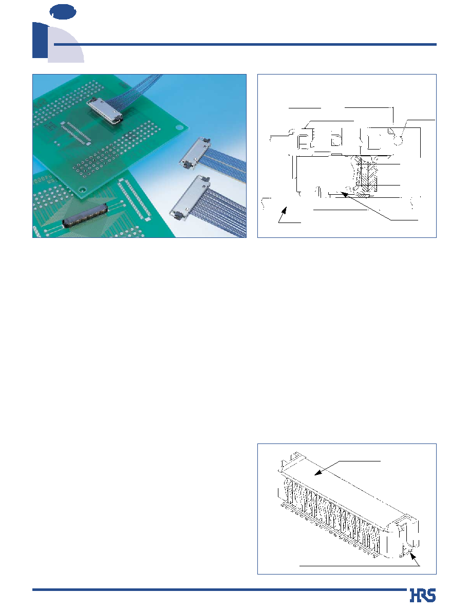
0.6mm Pitch Board-to-Fine-Coaxial Cable Connectors
DF21 Series
NEW
2002.11
s
Features
1.High Interconnection Reliability
Effective contact mating length of 1.55 mm, innovative bellow style contact design, built-in interlocking feature of
mated connectors assures high electrical and mechanical reliability, providing needed rigidity to resist
excessive twisting.
Superior reliability of the termination of the fine coaxial cable is accomplished with batch soldering.
2. Shielded design
Metal shell encloses the connector and makes contact with all external conductors of the fine coaxial cable
permitting reliable ground connection to the board side of mated assemblies.
3. Reliable mating/unmating
The connectors are self-align during mating.
Optional pull-out tab permits connection and disconnection in narrow spaces.
Polarized configuration prevents incorrect mating.
4. Board placement with Automatic Equipment.
The upper surface provides flat area for placement of embossed tape packaged connectors with vacuum
nozzles of automatic equipment.
s
Applications
Notebook computers, liquid crystal displays (LCD), video and
audio devices, medical instruments, portable devices and
any other device requiring reliable connection and
termination with fine pitch coaxial cable.
DF21-*P-0.6SD Plug
+DF21-*P-0.6SD-GND
(7)
(4.55)
DF21-*S-0.6V
PCB
Receptacle
DF21-
*P/DP-0.6PTB
Pull-out tab
1.55mm
Contact wipe
Receptacle
Flat surface
for placement
with Automatic
Equipment
Metal Hold-down
2
Measured at 100 V DC
Conduction of 150 V AC applied for 1 minute
Measured at 100 mA
Frequency of 10 to 55 Hz, single amplitude of 0.75 mm, in 3
directions, 2 hours
Temperature of 40
±
2
Á
, humidity of 90% to 95%, left standing
for 96 hours
(-55
Á
: 30minutes
/
5 to 35
Á
: 2 to 3minutes
/
85
Á
: 30minutes
/
5 to 35
Á
: 2 to 3minutes ) for 5 cycles
30 cycles (mating/unmating)
Reflow: at the recommended temperature profile, Solder: at a
soldering iron temperature of 300
Á
for 3 seconds
Solder bond: Within 5 seconds at 270
Á
max., Within 30 seconds at 200
Á
min. Hand soldering: Soldering iron temperature 300∞C, 3 seconds
500M
ohms
min.
No flashover or insulation breakdown
100m
ohms
max.
No electrical discontinuity of 1
µ
s or more.
Contact resistance of 100m
ohms
max., insulation
resistance of 50 M
ohms
min.
Contact resistance of 100m
ohms
max., insulation
resistance of 50 M
ohms
min.
Contact resistance of 100m
ohms
max.
No melting of the resin parts that will affect performance
No deformation of the insulator parts affecting performance.
1. Insulation resistance
2. Withstanding voltage
3. Contact resistance
4. Vibration
5. Humidity
6. Temperature cycle
7. Durability
8. Resistance to
Reflow heat
9. Resistance to
Soldering heat
Item
Specifications
Condition
s
Product Specifications
Ratings
Current rating
Voltage rating
50 V AC
Wire size
AWG #40: 0.3 A
AWG #36: 0.5 A
Operating temperature range
Operating humidity range
Storage temperature range
Storage humidity range
40% to 70% (Note 2)
-35
Á
to 85
Á
(Note 1)
20% to 80%
-10
Á
to 60
Á
(Note 2)
Note 1: Includes temperature rise caused by current flow.
Note 2: The term "storage" refers to products stored for long period of time prior to mounting and use. Operating Temperature Range
and Humidity range covers non- conducting condition of installed connectors in storage, shipment or during transportation.
s
Materials
Item
Part Material
Finish Remarks
Insulator
LCP
Black
UL94V-0
Receptacles
Contacts
Phosphor bronze
Gold plating
----------
Metal fittings
Phosphor bronze
Solder plating
----------
Insulator LCP
Black UL94V-0
Plugs
Contacts
Phosphor bronze
Gold plating
----------
Metal shell
Phosphor bronze
Solder plating
----------
Pull-out tab
Pull-out tab
Stainless steel
----------
----------
s
Ordering information
DF 21 -
*
P - 0.6 SD - GND
1
6
4
2
5
q
Receptacles/Plug
Series name
: DF21
Number of contacts
: 20, 30, 40
Connector type
S
: Single-row receptacle
P
: Single-row plug
Contact pitch
: 0.6 mm
Termination section
C
: Crimping plug
V
: Straight SMT
SD : Fine coaxial cable
Plug mounting parts
GND : Metal shell-required
PTB
: Pull-out tab-optional
1
4
5
6
2
3
3

3
Note : One reel contains 1,000 pieces package unit. Please order by the package unit.
s
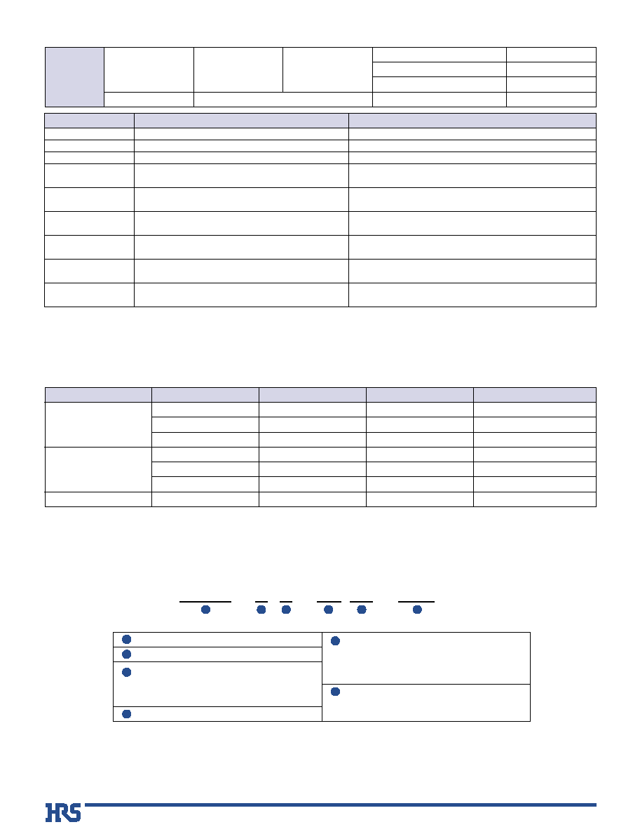
Receptacles
q
Embossed Carrier Tape Dimensions
P=0.6
q
Recommended PCB mounting pattern
(Note 1)
Product No.
CL No.
Number of Contacts
A
B
C
D
E
F
DF21-20S-0.6V(51)
687-0001-5-51
20
15.2
11.4
11.5
24
12.6
DF21-30S-0.6V(51)
687-0003-0-51
30
21.2
17.4
14.2
28.4
32
18.6
DF21-40S-0.6V(51)
687-0002-8-51
40
27.2
23.4
20.2
40.4
44
24.6
Unit: mm
[Specifications number] -
* *
, (
* *
)
(51) : Embossed tape packaging (1,000 pieces per reel)
0.2
A
B
P=0.6
2±0.1
12±0.1
ÿ1.5
+1.5
0
4±0.1
t=0.4±0.1
2±0.5
(
E+0.4
)
(E+6.4)MAX
+2
0
+0.1
0
ÿ13±0.2
ÿ21±0.8
Product
name
label
Unreeling direction
0.2
3.2
3
0.4
1.75±0.1
2±0.1
B±0.03
F±0.05
P=0.6±0.03
0.35±0.02
1.75±0.1
C±0.1
2.6±0.05
2.3±0.05
D±0.1
(ÿ80)
ÿ330±2
3.8
E±0.3
3.8
1.3
+0.1
0
1.6
4
Note 1: The 40 contact type is being planned.
Note 2: One package unit contains 100 pieces. Please order by the package unit.
Note 1: The pitch maintaining tape can be left in place during the termination process. Use high quality tape.
Note 2: When using 2-conductor coaxial cable, some contact positions will not be usable.
Note 2:
Contact nearest Hirose sales office for recommendation on specific application.
Note 3: Contact Hirose for Termination Procedures.
s
Plugs
q
Recommended Fine Coaxial Cable Preparation
Product No.
CL No.
Number of Contacts
A
B
C
DF21-20P-0.6SD
687-1500-0
20
22.5
11.4
15
DF21-30P-0.6SD
687-1502-6
30
28.5
17.4
21
DF21-40P-0.6SD
687-1501-3
40
34.5
23.4
27
Unit: mm
0
-0.3
C±0.5
0.4max
Ground bar
Insulator
Outer shield
(for individual conductor)
Fine coaxial cable
Jacket
B±0.15
C±0.3
P=0.6±0.1
Inner conductor
(Solder coating required)
Pitch maintaining
tape
A
B
P=0.6
1.1MIN
4.1MAX
2.75MIN
6.8
4.45
1.1
+0.10 -0.05
1.0
0
0.0
-0.05
0.55
Shown with optional
Pull-out Tab
5
Note 1: One package unit contains 100 pieces. Please order by the package unit.
Note 2: The metal shell is an absolutely necessary part at the time of wiring.
s
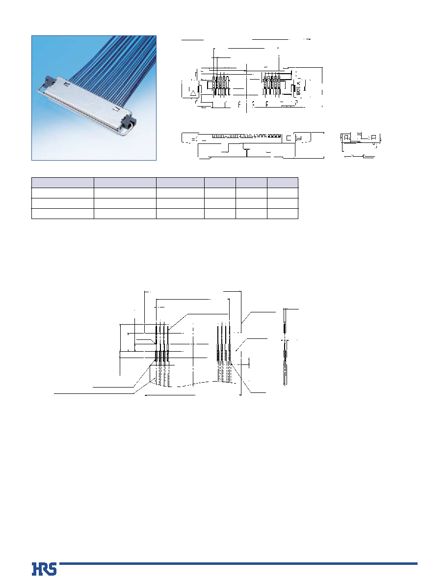
Metal shell-Required for assembly of the Plug
s
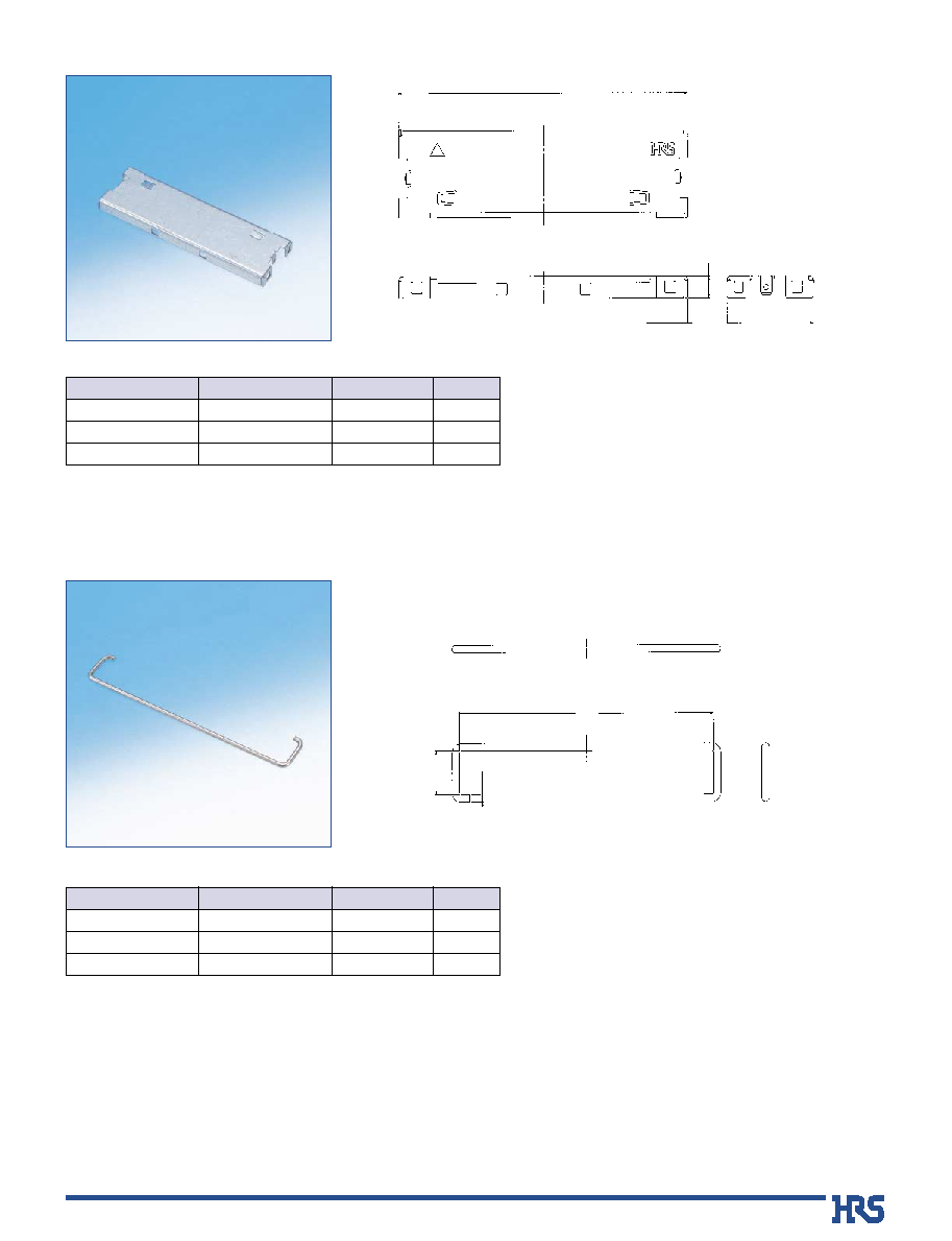
Pull-out Tab (Optional for Plug)
Note: One package unit contains 100 pieces. Please order by the package unit.
t=0.2
A
7
A
1.75
3.5
ÿ0.6
Product No.
CL No.
Number of Contacts
A
DF21-20P/40DP-0.6PTB
687-1700-0
20
20.9
DF21-30P/60DP-0.6PTB
687-1701-2
30
26.9
DF21-40P/80DP-0.6PTB
687-1702-5
40
32.9
Unit: mm
Product No.
CL No.
Number of Contacts
A
DF21-20P-0.6SD-GND
687-2500-6
20
17.7
DF21-30P-0.6SD-GND
687-2502-1
30
23.7
DF21-40P-0.6SD-GND
687-2501-9
40
29.7
Unit: mm
6
B
Usage Recommendations
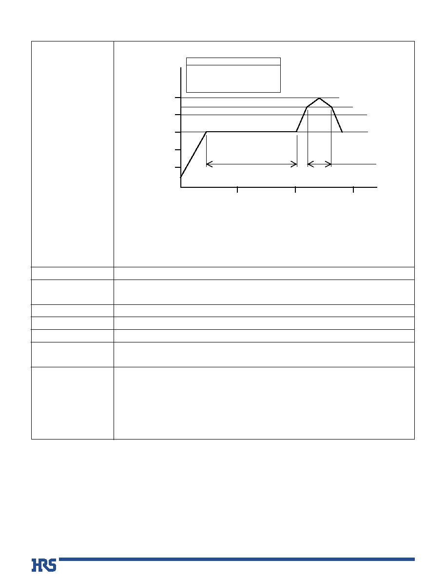
Note 1: Up to 2 cycles of reflow soldering are possible under the same conditions, provided that
there is a return to normal temperature between the first and second cycle.
Note 2: The temperature profile indicates the board surface temperature at the point of contacts
with the connector terminals (for surface mounted plug assembly).
1. Recommended
Temperature Profile
1. Recommended
2. Receptacle Recommended
Manual Soldering Conditions
3. Recommended Screen Thickness
4. Board Warping
5. Cleaning Conditions
6. Plug Recommended
Soldering Conditions
7. Handling and use
precautions
sDO NOT mate/un-mate non-terminated plugs with non-mounted receptacles.
This may lead to damage or deformation of the contacts.
sDO NOT touch the exposed contacts of the receptacle with bare fingers. This may leave non-conductive film,
cause corrosion or electrostatic discharge, affecting performance of the connectors or sensitive electronic
components.
sDO NOT apply flux to the contact terminals when hand soldering the receptacle to the board. Wicking of the
flux into the electrical contact areas may lead to connection failures.
Soldering temperature: 290Á ±10Á, Soldering time: within 2 sec.
Soldering temperature: 290Á ±10∞C, soldering time: within 2 sec.
0.15mm
Maximum of 0.03 mm at the connector center section, with both ends of the connector as reference points.
Refer to "Nylon Connector Use Handbook."
260Á ±5Á within 5 sec, 200Á min. within 25 sec.
0Á
50Á
100Á
150Á
150
Á for 30 to 90 sec.
235
Á±5Á for 10 sec max.
220
Ámin. for 10 to 20 sec.
200Á
250Á
Temperature
50 s
Preheating
IR re-flow
Preheating :
Soldering :
Soldering
0 s
90 s
150 s Time
240Á max.
220Á