NEW
1
7.92 mm Contact Pitch, High-Current Connectors for Internal Power Supplies (UL, C-UL and TÐV Listed)
DF22 Series
2004.5
s
Features
1. 30 A maximum current
Single position connector can carry current of 30 A with #10 AWG
conductor. Please refer to Table #1 for current ratings for multi-
position connectors using other conductor sizes.
2. Complete Locking Function
Reliable interior lock protects mated connectors from
accidental disconnection.
3. Prevention of Incorrect Connections
To prevent incorrect connection when using multiple connectors
having the same Number of contacts, 3 product types having
different mating configurations are available.
4. Molded-in contact retention tabs
Handling of terminated contacts during the crimping is easier
and avoids entangling of wires, since there are no protruding
metal tabs.
5. Prevention of incorrect board placement
Built-in posts assure correct connector placement and
orientation on the board.
6. Supports encapsulation
Connectors can be encapsulated up to 10 mm without affecting
the performance.
7. Prevention of Short Circuits Between Adjacent Contacts
Each Contact is completely surrounded by the insulator
housing electrically isolating it from adjacent contacts.
8. Increased Retention Force of Crimped Contacts and
confirmation of complete contact insertion
Separate contact retainers are provided for applications where
extreme pull-out forces may be applied against the wire or when a
visual confirmation of the full contact insertion is required.
9. Full Line of Crimp Socket Contacts
Realizing the market needs for multitude of different applications, Hirose
has developed several variants of crimp socket contacts and housings.
Continuous development is adding different variations. Contact your
nearest Hirose Electric representative for latest developments.
10. In-line Connections
Connectors can be ordered for in-line cable connections. In addition,
assemblies can be placed next to each other allowing 4 position total
(2
2) in a small space.
11. Listed by UL, C-UL, and TÐV.
s
Applications
Office equipment, power supplies for industrial, medical
and instrumentation applications, variety of consumer
electronic, and electrical applications.
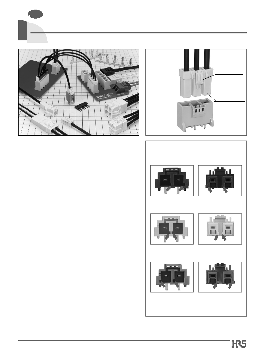
Prevention of Incorrect Connections
Complete
Locking
Function
q
R Type (Guide key: right side, Color: black)
q
Standard Type (Guide key: inside, Color: natural)
q
L Type (Guide key: left side, Color: red)
*
The photographs on the left show header (the board dip side),
the photographs on the right show the socket (cable side).
*
The guide key position is indicated in position facing
the mating surface of the header.
Completely
enclosed
locking system
Protection from
shorts circuits
between adjacent
Contacts
2
s
Product Specifications
Ratings
Current
rating
Voltage
rating
Specification
UL/C-UL
TÐV
AC/DC 1000V
AC/DC 600V
AC/DC 600V
Number of contacts
1
2
3
4
5
AWG10
30A
25A
25A
22A
22A
AWG12
25A
20A
20A
18A
18A
AWG14
20A
18A
18A
15A
15A
AWG16
15A
15A
15A
13A
13A
Operating temperature range
Operating humidity range
Storage temperature range
Storage humidity range
UL/C-UL/TÐV
File No. and Recognition No.
UL
: E52653
C-UL
: E52653
TÐV
: R9950703
-35
Á
to 85
Á
(Note 1)
20% to 80%
-10
Á
to 60
Á
(Note 2)
40% to 70% (Note 2)
20mV max., 1mA
1000 V DC
2500 V AC for 1 minute
Measured with a steel pin of 1.6 x 0.8
±
0.002 thickness
30 cycles
Frequency 10 to 55 Hz, single amplitude of 0.75 mm, 3 axis, duration of 2 hours
Acceleration of 490 m/s
2
, 11 ms duration, sine half-wave waveform, 3 cycles in each of the 3 axis.
Temperature 40
Á ±
2
Á
, 90% to 95% RH, 96 hours
(-55
Á
: 30 minutes
5 to 35
Á
: 5 minutes
85
Á
: 30 minutes
5 to 35
Á
: 5 minutes) for 5 cycles
Contact resistance(Initial value): 5 m ohms max.
1000 M ohms min.
No flashover or Insulator breakdown
0.3N min., 5N max.
Contact resistance of 10 m ohms max.
No electrical discontinuity of 1
µ
s. min.
No electrical discontinuity of 1
µ
s. min.
Contact resistance 10 m ohms max.
Contact resistance of 10 m ohms max.
No deformation of the insulator parts affecting performance
1. Contact resistance
2. Insulator resistance
3. Withstanding voltage
4. Insertion-Extraction force (per contact)
5. Durability (mating/unmating)
6. Vibration
7. Shock
8. Humidity
9. Temperature cycle
10. Resistance to Soldering heat
Item
Specification
Condition
s
Ordering Information
DF22 B L - 2 S - 7.92 C
1
4
3
6
2
5
7
Number of contacts : 1 to 5
Contact pitch
: 7.92 mm
Type of housing
C
: Crimp housing
DSA
: Straight header
DS
: Right-angle header
No letter : Retainer
Connector type
S
: Socket
DS
: Double-row socket
P
: Header
EP
: In-line plug
DEP
: Double-row in-line plug
RS/P
: Retainer
Series name: DF22
Guide key type
Blank : Inside (Color: natural)
R : Right side (Color: black)
L : Left side (Color: red)
Form Type
Sockets
Blank : Standard height, standard lock (Type I)
B : Long type, standard lock (Type III)
C : Long type, ergonomic lock (Type IV)
In-line Plugs
Blank : With panel stop
A : Without panel stop
Applicable Cable
Blank : UL1430
A
: UL1015
Applicable Conductor
1416 : AWG 14 to AWG 16
1012 : AWG 10 to AWG 12
Packaging
SCF : Socket contacts / Reel
SC
: Socket contacts / Bag
PCF : In-line plug contacts / Reel
PC
: In-line plug contacts / Bag
1
4
5
6
7
8
9
10
2
3
Note 1: Current rating of header is 30A (1 pos.) and 25A (2 to 5 pos.)
Note 2: Includes temperature rise caused by the current flow.
Note 3: The term "storage" refers to products stored for long period of time prior to mounting and use. Operating Temperature Range and Humidity
range covers non- conducting condition of installed connectors in storage, shipment or during transportation.
Note 1: Standard Color, colors of the differing coupling forms are black for DF22R and red for DF22L.
Note 2: Hirose Electric's plating incorporate anti-whisking compounds.
s
Materials
Remarks
UL94V-0
----------
UL94V-0
----------
Product
Part
Material
Finish
Sockets
Crimp contacts
Headers
Insulator
Contacts
Insulator
Contacts
Polyamide
High conductivity copper alloy
Polyamide (Glass reinforced)
High conductivity copper alloy
Color: Natural white
(Note 1)
Tin-lead plated
(Note 2)
Color: Natural beige
(Note 1)
Tin-lead plated
(Note 2)
q
Socket, Header
DF22 A - 1416 SCF
1
9
8
10
q
Contacts
Re-flow solder temperature 250
Á
, for 10 seconds
Manual soldering: Soldering iron temperature 300
Á
, 3 seconds
3
Note: Bag packaging (100 pieces/bag). Order by number of bags.
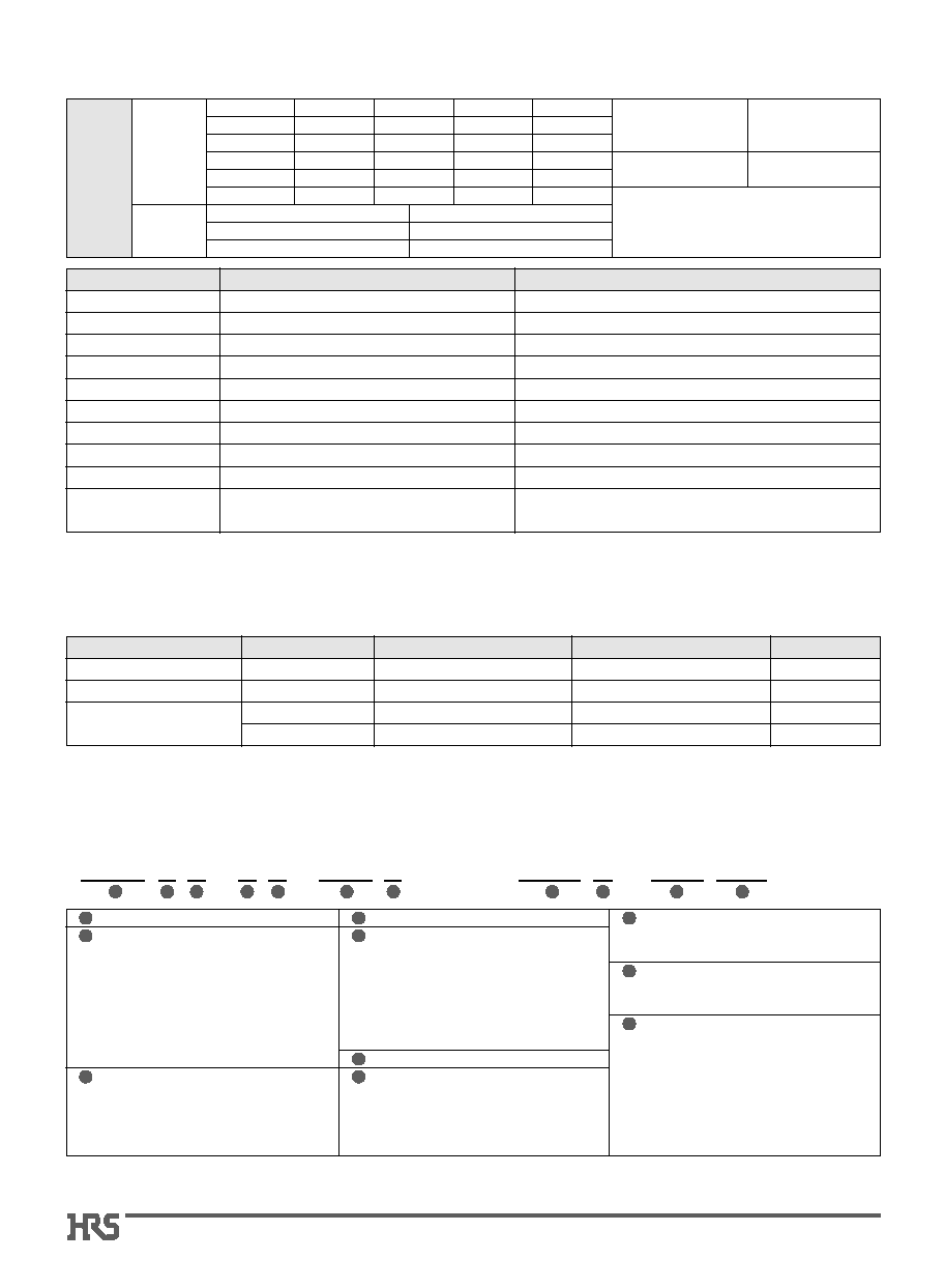
s
Type I
Height: Standard type, Standard lock
Note: The part number and CL No. have changed to accommodate
the product form change of the 2 to 5 pos. types.
Shown with terminated and installed contacts.
CL No.
Part Number
Number of contacts
A
B
DF22-1S-7.92C(28)
DF22-2S-7.92C(28)
DF22-3S-7.92C(28)
DF22-4S-7.92C(28)
DF22-5S-7.92C(28)
1
2
3
4
5
8.00
15.50
23.42
31.34
39.26
-----
7.92
15.84
23.76
31.68
Standard Type (Guide Key: Inside, Color: White)
Type 1
Standard lock
1
A
(11.55)
No. of contacts
indicator
Cavity No.
14.5
20
8
7.7
Type 1
Standard lock
3
A
(11.55)
Contact No. 1
No. of contacts
indicator
Cavity No.
Contact No. 1
indicator
A
B
P=7.92
7.7
10.4
14.5
20
1 Pos.
2 to 5 Pos.
680-1012-2-28
680-1004-4-28
680-1005-7-28
680-1006-0-28
680-1007-2-28
Shown with terminated and installed contacts.
s
Crimp Sockets (Standard Type)
CL No.
Part Number
Number of contacts
A
B
DF22R-1S-7.92C(28)
DF22R-2S-7.92C(28)
DF22R-3S-7.92C(28)
DF22R-4S-7.92C(28)
DF22R-5S-7.92C(28)
1
2
3
4
5
8.00
15.50
23.42
31.34
39.26
-----
7.92
15.84
23.76
31.68
R Type (Guide Key: Right Side, Color: Black)
680-1026-7-28
680-1027-0-28
680-1028-2-28
680-1029-5-28
680-1030-4-28
CL No.
Part Number
Number of contacts
A
B
DF22L-1S-7.92C(28)
DF22L-2S-7.92C(28)
DF22L-3S-7.92C(28)
DF22L-4S-7.92C(28)
DF22L-5S-7.92C(28)
1
2
3
4
5
8.00
15.50
23.42
31.34
39.26
-----
7.92
15.84
23.76
31.68
L Type (Guide Key: Left Side, Color: Red)
680-1031-7-28
680-1032-0-28
680-1033-2-28
680-1034-5-28
680-1035-8-28

4
s
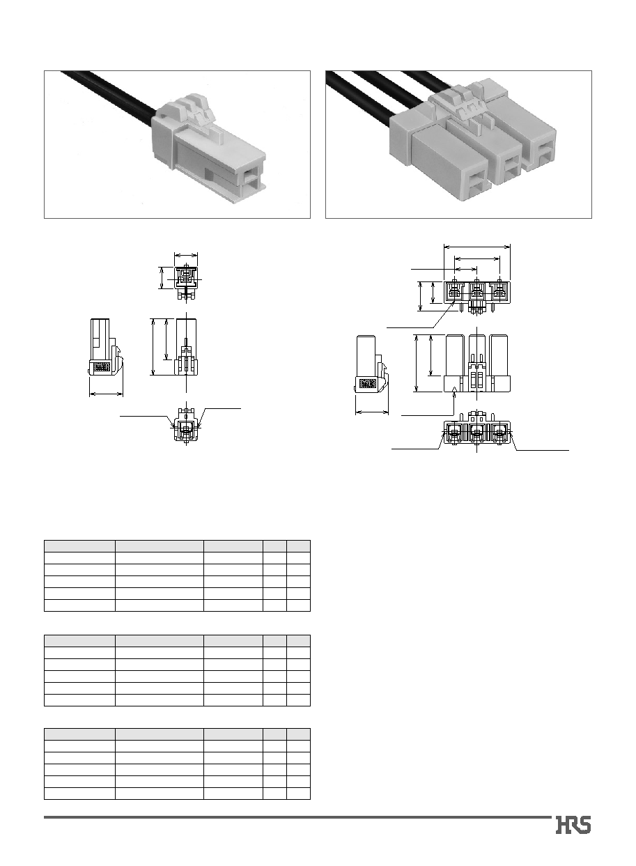
Type III
Height: Long type, Standard lock
s
Type IV
Height: Long type, Enhanced ergonomic lock
Shown with terminated and installed contacts.
Type 4
Height: Long type,
Enhanced
ergonomic lock
Type 3
Height: Long type,
Standard lock
1
A
(11.55)
(12.75)
14.5
23
8
7.7
No. of contacts
indicator
Cavity No.
Type 4
Height: Long type,
Enhanced
ergonomic lock
Type 3
Height: Long type,
Standard lock
3
A
Contact No. 1
(12.75)
(11.55)
No. of contacts
indicator
Cavity No.
Contact No. 1
indicator
A
B
P=7.92
7.7
10.4
14.5
23
1 Pos.
2 to 5 Pos.
Shown with terminated and installed contacts.
s
Crimp Sockets (Height, Long Type)
Note: Bag packaging (100 pieces/bag). Order by number of bags.
CL No.
Part Number
Number of contacts
A
B
DF22B-1S-7.92C
DF22B-2S-7.92C
DF22B-3S-7.92C
DF22B-4S-7.92C
DF22B-5S-7.92C
1
2
3
4
5
8.00
15.50
23.42
31.34
39.26
-----
7.92
15.84
23.76
31.68
Standard Type (Guide Key: Inside, Color: White)
680-1096-2
680-1097-5
680-1098-8
680-1099-0
680-1100-8
CL No.
Part Number
Number of contacts
A
B
DF22BR-1S-7.92C
DF22BR-2S-7.92C
DF22BR-3S-7.92C
DF22BR-4S-7.92C
DF22BR-5S-7.92C
1
2
3
4
5
8.00
15.50
23.42
31.34
39.26
-----
7.92
15.84
23.76
31.68
R Type (Guide Key: Right Side, Color: Black)
CL No.
Part Number
Number of contacts
A
B
DF22BL-1S-7.92C
DF22BL-2S-7.92C
DF22BL-3S-7.92C
DF22BL-4S-7.92C
DF22BL-5S-7.92C
1
2
3
4
5
8.00
15.50
23.42
31.34
39.26
-----
7.92
15.84
23.76
31.68
L Type (Guide Key: Left Side, Color: Red)
CL No.
Part Number
Number of contacts
A
B
DF22CL-1S-7.92C
DF22CL-2S-7.92C
DF22CL-3S-7.92C
DF22CL-4S-7.92C
DF22CL-5S-7.92C
1
2
3
4
5
8.00
15.50
23.42
31.34
39.26
-----
7.92
15.84
23.76
31.68
L Type (Guide Key: Left Side, Color: Red)
Reserved for
product expansion
CL No.
Part Number
Number of contacts
A
B
DF22CR-1S-7.92C
DF22CR-2S-7.92C
DF22CR-3S-7.92C
DF22CR-4S-7.92C
DF22CR-5S-7.92C
1
2
3
4
5
8.00
15.50
23.42
31.34
39.26
-----
7.92
15.84
23.76
31.68
R Type (Guide Key: Right Side, Color: Black)
CL No.
Part Number
Number of contacts
A
B
DF22C-1S-7.92C
DF22C-2S-7.92C
DF22C-3S-7.92C
DF22C-4S-7.92C
DF22C-5S-7.92C
1
2
3
4
5
8.00
15.50
23.42
31.34
39.26
-----
7.92
15.84
23.76
31.68
Standard Type (Guide Key: Inside, Color: White)
680-1101-0
680-1102-3
680-1103-6
680-1104-9
680-1105-1
Reserved for
product expansion
Reserved for
product expansion
Reserved for
product expansion
5
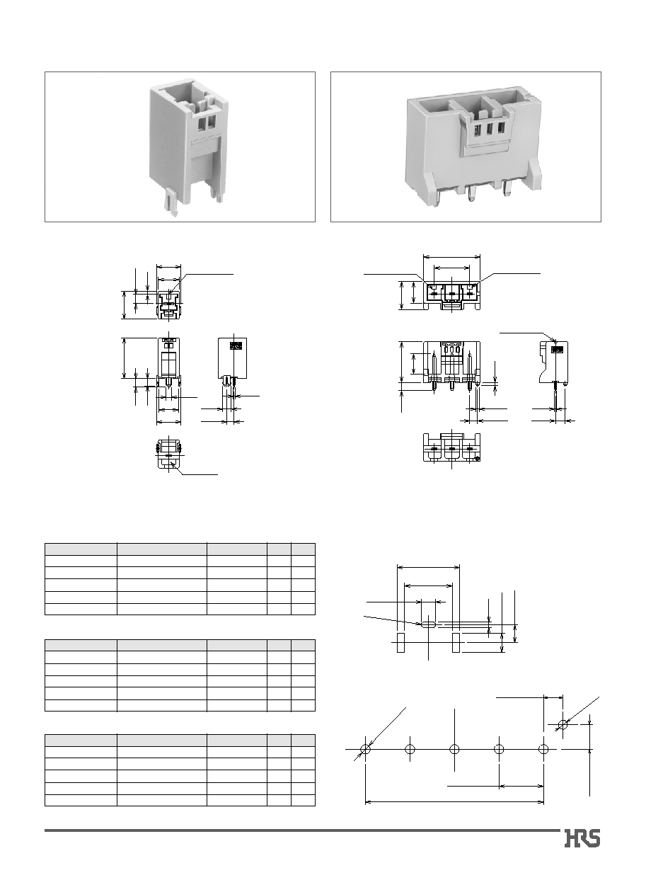
B
PCB mounting pattern
(Board thickens: 1.6±0.1)
Cavity No.
No. of contacts
indicator
10.8
2.3
0.8
9.3
1.5
4.05
12.45
18.1
3.7
10.8
3.2
3.2
3.9
8.7
A
1
Cavity No.
No. of contacts
indicator
Contact No. 1
indicator
A
B
9.7
12.45
9
18.1
3.7
1.4
ÿ1.5
3.45
0.8
4.35
A
3
1 Pos.
2-R0.5
2.5
+0.1
0
1
+0.1 0
8.5
+0.1
--0.2
11.1±0.1
3.4±0.1
3.2±0.05
1 Pos.
4.35±0.05
3.45±0.05
ÿ1.6
+
0.1
0
P=7.92±0.05
B±0.05
*-ÿ1.7
+
0.1
0
2 to 5 Pos.
2 to 5 Pos.
s
Straight header
Note: Bag packaging (100 pieces/bag). Order by number of bags.
CL No.
Part Number
Number of contacts
A
B
DF22-1P-7.92DSA
DF22-2P-7.92DSA
DF22-3P-7.92DSA
DF22-4P-7.92DSA
DF22-5P-7.92DSA
1
2
3
4
5
10.08
17.22
25.14
33.06
40.98
-----
7.92
15.84
23.76
31.68
Standard Type (Guide Key: Inside, Color: Natural Beige)
680-1013-5
680-1014-8
680-1015-0
680-1016-3
680-1017-6
CL No.
Part Number
Number of contacts
A
B
DF22R-1P-7.92DSA
DF22R-2P-7.92DSA
DF22R-3P-7.92DSA
DF22R-4P-7.92DSA
DF22R-5P-7.92DSA
1
2
3
4
5
10.08
17.22
25.14
33.06
40.98
-----
7.92
15.84
23.76
31.68
R Type (Guide Key: Right Side, Color: Black)
680-1036-0
680-1037-3
680-1038-6
680-1039-9
680-1040-8
CL No.
Part Number
Number of contacts
A
B
DF22L-1P-7.92DSA
DF22L-2P-7.92DSA
DF22L-3P-7.92DSA
DF22L-4P-7.92DSA
DF22L-5P-7.92DSA
1
2
3
4
5
10.08
17.22
25.14
33.06
40.98
-----
7.92
15.84
23.76
31.68
L Type (Guide Key: Left Side, Color: Red)
680-1041-0
680-1042-3
680-1043-6
680-1044-9
680-1045-1