Äîêóìåíòàöèÿ è îïèñàíèÿ www.docs.chipfind.ru
1
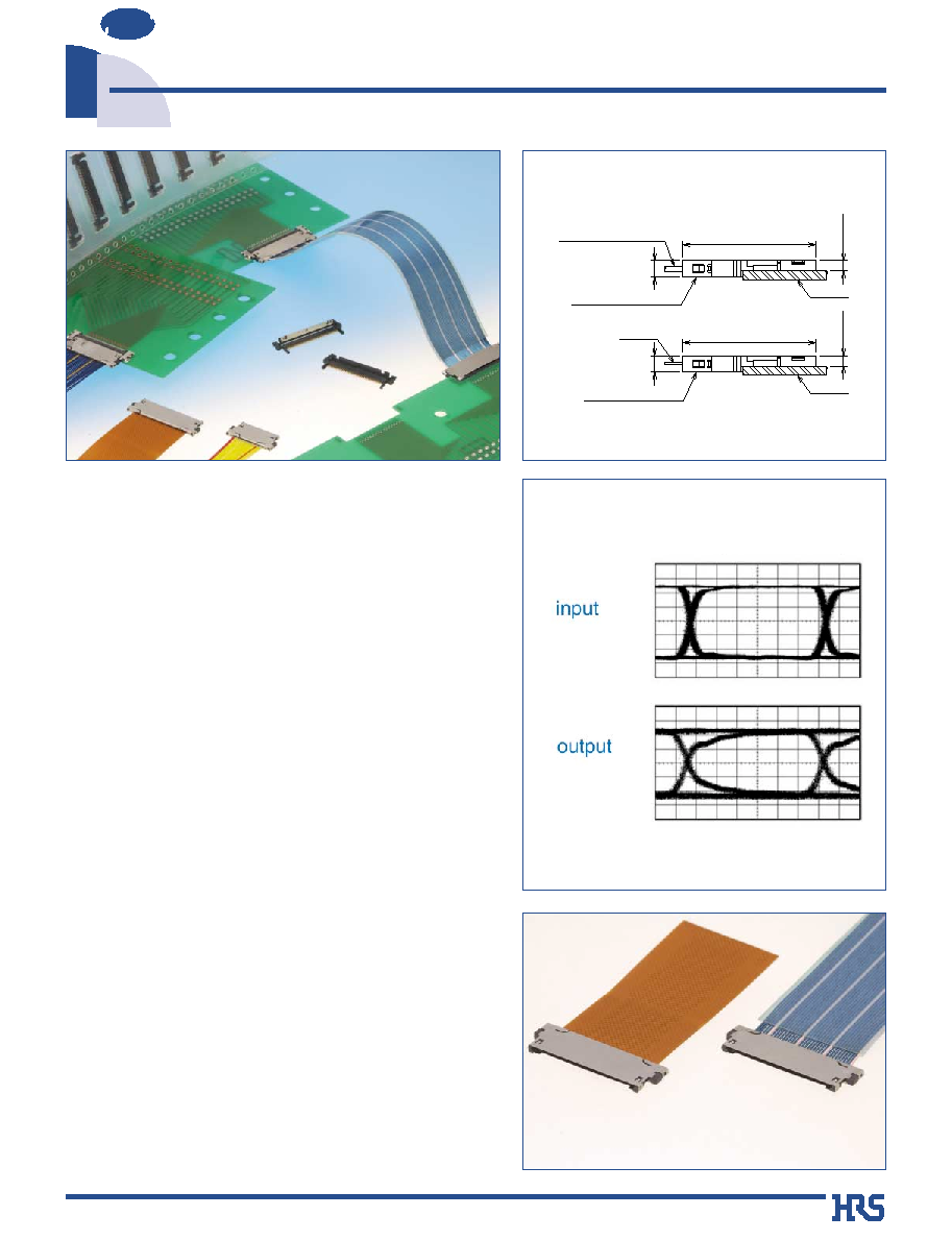
0.5 mm Contact Pitch, Board-to-FPC, Board-to-Fine Coaxial Ribbon Cable
DF25 Series
NEW
2003.5
s
Features
1. Supports High Speed Data Transfer
Typical Data Transfer of 1.2 Gbps. Up to 2 Gbps in
specific applications.
*The transmission characteristics depends on the
specific conditions and may vary. It is recommended
that verification be made with the actual device in use.
2. Small configuration and board space
0.5 mm contact pitch and body thickness of 1.1 mm. max.
3. Common Use of Receptacle
The board mounted receptacle assembly will accept
mating connectors terminated to FPC or Fine Coaxial
Cable Ribbon Cable.
4. Uniform External Dimensions
The Plug Assembly external dimensions remain the
same when it is terminated with FPC or the Fine Pitch
Coaxial Ribbon Cable.
5. Ground Connection
Metal Shield Covers connect with the common ground line.
6. Easy Termination of FFC or Fine Coaxial
Ribbon Cable
Hirose Electric's unique termination method allows
reduction of the number steps to terminate FFC or Fine
Coaxial Ribbon Cable. Termination can be performed in
any work environment since there is no need for the
electric power supply.
7. Environmental considerations
Plating compounds are lead-free.
s
Applications
LCD connections in small consumer devices, Digital
Cameras, Notebook computers, PDA's.
Any device requiring high density interconnection for
consistent high speed transmission data rates.
(0.7)
(0.7)
(8.9)
(1.1)
(1.1)
(8.9)
Board
Board
Fine Coaxial
Ribbon Cable
FPC
DF25G-*S-0.5SD
DF25G-*S-0.5F
2 Gbps Eye Pattern
FPC Type
Fine Coaxial
Ribbon Cable Type
2
100 V DC
200 V AC / one minute
100 mA
Measured with a steel pin 0.150.26±0.005
Frequency: 10 to 55 Hz, single amplitude of 0.75 mm, 2 hours in
each of the 3 directions
96 hours at temperature of 40ç and humidity of 90% to 95%
Temperature: -55ç ¡ +5ç to +35ç ¡ +85ç ¡ +5ç to +35ç
Time sequence: 30 ¡ 10 ¡ 30 ¡ 10 (Minutes) 5 cycles
30 cycles
Re-flow soldering: At the recommended temperature profile
Manual soldering: Soldering iron temperature 300ç, 3 seconds
500 M ohms min.
No flashover or insulation breakdown
50 m ohms max.
Min. 0.15n, Max. 2N
No electrical discontinuity of 1 µs or more.
Contact resistance: 120 m ohms max.
Insulation resistance: 500 M ohms min.
Contact resistance: 120 m ohms max.
Insulation resistance: 500 M ohms min.
Contact resistance: 120 m ohms max.
No deformation of the insulator parts affecting
performance.
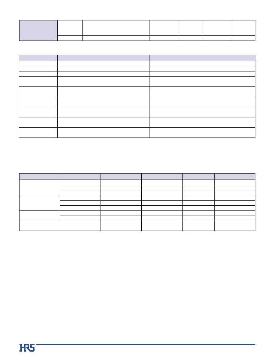
1. Insulation resistance
2. Withstanding voltage
3. Contact resistance
4. Insertion-Extraction force
(per contact)
5. Vibration
6. Humidity(Steady state)
7. Temperature cycle
8. Durability
(insertion/ withdrawal)
9. Resistance to
soldering heat
Item
Specification
Conditions
s
Materials
Product
Part
Material
Finish
Color
Remarks
Receptacle
FPC Plug
Fine Coaxial
Ribbon Cable Plug
Insulator
Contacts
Shield plate
Insulator
Contact
Shield plate
Insulator
Contact
Glass reinforced thermoplastic
Phosphor bronze
Phosphor bronze
Glass reinforced thermoplastic
Phosphor bronze
Phosphor bronze
Glass reinforced thermoplastic
Phosphor bronze
Stainless steel
----------------
Gold plating
Tin plating
----------------
Gold plating
Tin plating
----------------
Gold plating
Obverse side: Tin plating
Reverse side: Insulation coating
Black
----------------
----------------
Black
----------------
----------------
Black
----------------
----------------
UL94V-0
----------------
----------------
UL94V-0
----------------
----------------
UL94V-0
----------------
----------------
s
Product Specifications
Ratings
FPC: 0.5 A DC (Note 1)
Current rating Fine Coaxial Ribbon Cable AWG#36: 0.5A
Fine Coaxial Ribbon Cable AWG#40: 0.3A
Voltage rating 50 V AC
Operating temperature -35ç to +85ç (Note 2)
Operating humidity
20% to 80%
Operating temperature -10ç to +60ç (Note 3)
Operating humidity
40% to 70% (Note 3)
Note 1: Please contact FPC manufacturer for specifications.
Note 2: Includes temperature rise caused by current flow.
Note 3: The term "storage" refers to connectors stored for long period of time prior to mounting and use. Operating
Temperature Range and Humidity range covers non- conducting condition of installed connectors in storage,
shipment or during transportation.
Shield Cover
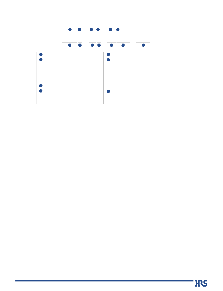
3
Contact pitch :0.5mm
Termination section
H: Right angle SMT
F: FPC Plug
SD: Plug - Fine Pitch Coaxial Ribbon Cable
F/SD: Common to FPC Plug & Fine
Coaxial Ribbon Cable Plug
Metal shell
G: Shielding plate
s
Ordering information
DF25 L - 36
Ordering Information : DF25
Configuration
Receptacle
L: Offset type (0.7mm above the board)
Plug
G: Ground connection type
Number of contacts: 20,30,36
Connector type
S: Plug
P: Receptacle
1
2
3
4
5
6
7
1
2
3
5
P
4
- 0.5
6
H
DF25 G - 36
1
2
3
5
S
4
- 0.5 F/SD
6
7
- GND
4
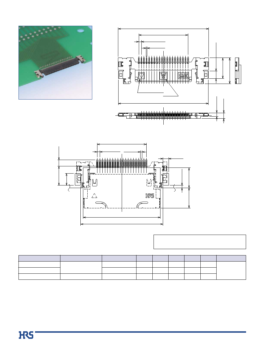
s
Right angle Receptacle (SMT)
(Offset mounting type)
Note: Embossed tape reel packaging (2,000 pieces/reel).Order by number of reels.
P=0.5±0.08
0.2±0.05
B±0.15
A±0.3
1.42±0.1
4±0.3
5±0.3
1.1 MAX
0.7±0.15
C±0.3
CAV No.
Contact No. 1
identification mark
B
PCB mounting pattern
0.3±0.05
D±0.1
(3.9)
P=0.5±0.05
B±0.05
E±0.1
0.5±0.1
3.9±0.1
1.1
+0.1
0
2.3
+0.1 0
3.7±0.1
1.2
+0.1 0
Packaging code: -**,(**)
(51): Embossed tape packaging (2,000 pieces per reel)
Part Number
DF25L-20P-0.5H(**)
DF25L-30P-0.5H(**)
DF25L-36P-0.5H(**)
CL No.
Reserved for
product expansion
662-0009-0-**
Number of contacts
20
30
36
A
17.46
22.46
25.46
B
1
9.5
14.5
17.5
C
17.5
22.4
25.4
D
14.9
19.9
22.9
E
15.9
20.9
23.9
Remarks
0.7mm above
the board
Unite: mm
5
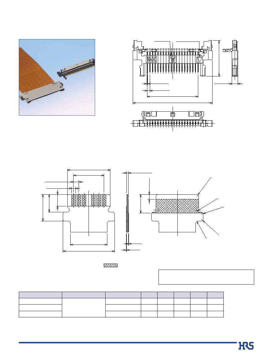
s
Plug (FPC Type)
Note 1: Requires use of plug and shield cover.
Note 2: Requires use of dedicated assembly tools.
Note: Bag packaging (100 pieces/bag).Order by number of bags.
CAV No.
0.15±0.08
Contact No. 1
P=0.5±0.1
6.7±0.3
1.1MAX
B±0.3
A±0.3
B
FPC pattern
0.35±0.03
t=0.145±0.03
B±0.05
P=0.5±0.03
1.1
+0.3
- 0.05
1.65±0.05
2.5±0.05
C±0.05
D±0.05
E±0.05
R0.2±0.05
R0.2±0.05
R0.2±0.05
R0.2±0.05
MAXR0.2
0.45
+0.1
0
1.75
+0.3
- 0.05
Solder plated area: 1 to 5µm thick
0.05
0.05
Packaging code: -**,(**)
No symbol: Bag packaging (100 pieces per bag)
Part Number
DF25G-20S-0.5F(**)
DF25G-30S-0.5F(**)
DF25G-36S-0.5F(**)
CL No.
Under development
Number of contacts
20
30
36
A
14.9
19.9
22.9
B
1
9.5
14.5
17.5
C
10.65
15.65
18.65
D
10.1
15.1
18.1
E
11.5
16.5
19.5
Unite: mm