1
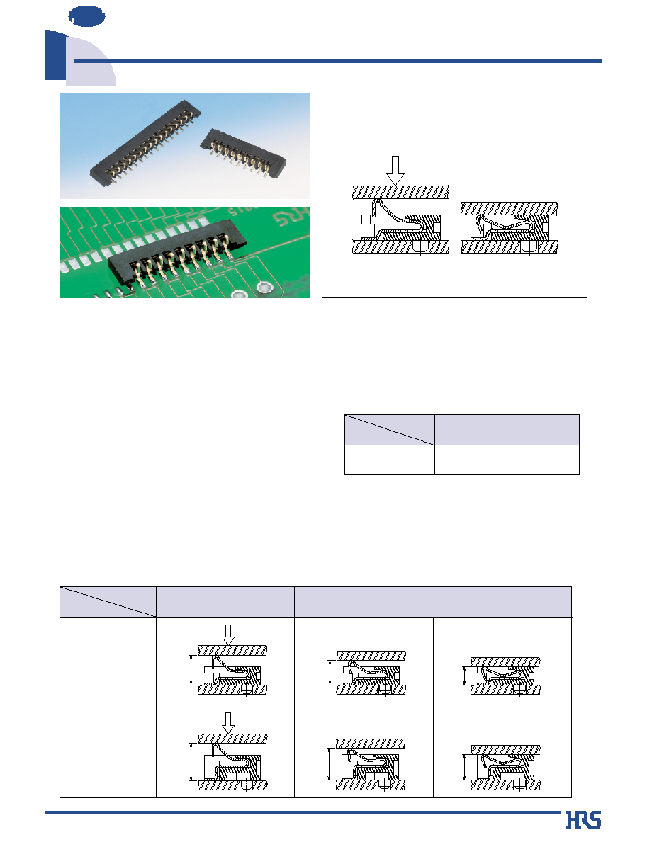
1.1mm Pitch Low Profile Compression Connectors
DF26 Series
NEW
2003.7
s
Features
1. Low Profile
Connectors are available in heights : 1.2mm and
1.7mm.
2. Miniature, Space-Saving Design
The space-saving design of these connectors permits
increase in the mounting density as compared to
equivalent products.
3. One-Piece Connector
These connectors support cost reduction requirement
since there is no need for a mating half connector.
This design also permits a reduction in the number of
assembly steps.
4. Variations
Press in
Compression Connectors
-Mating height: 1.2mm and 1.7mm
9 Contacts 16 Contacts 18 Contacts
Number of Contacts
Mating Height
1.2mm
Under development
1.7mm
Item
Product
Before Contact
Contacting (Effective Mating Height)
1.2mm
1.7mm
1.55mm
Press down
2.05mm
1.2mm
1.7mm
1.55mm
Press in
1.9mm
1.2mm
Press in
2.4mm
2.05mm
1.7mm
s
Applications
LCD, cellular phones, notebook computers, miniature office automation
equipment, and miniature consumer products.
Press down
Press down
100 V DC
150 V AC / one minute
100 mA
Frequency: 10 to 55 Hz, single amplitude of 0.75 mm,
2 hours in each of the 3 directions
96 hours at temperature of 40
±
2
Á
and humidity of 90
%
to 95
%
Temperature: -55
Á °
+5
Á
to +35
Á °
+85
Á °
+5
Á
to +35
Á
Time sequence: 30
°
10
°
30
°
10 (Minutes)
5 cycles
50 stroke cycles
Reflow soldering: At recommended temperature profile
Manual soldering: Soldering iron temperature 300
Á,
3 seconds
500 M
ohms
min.
No flashover or insulation breakdown
50 m
ohms
max.
No electrical discontinuity of 1
µ
s or more
Below the contact resistance standard value.
Insulation resistance: 500 M min.
Below the contact resistance standard value.
Insulation resistance: 500 M
ohms
min.
Below contact resistance standard value
No deformation of the insulator parts
affecting performance.
1. Insulation resistance
2. Withstanding voltage
3. Contact resistance
4. Vibration
5. Humidity
6. Temperature cycle
7. Stroke life
8. Resistance to
soldering heat
2
s
Ordering Information
DF26
1
#
2
1.2
3
-
*
4
CP - 1.1
5
6
V
7
(
* *
)
8
Boss type
A: With boss
Series name: DF26
Connector type
CP: Single row compression
Number of contacts: 9, 16
Mating height
1.2: 1.2mm
1.7: 1.7mm
Contact type
V: Straight SMT
Packaging
(51): Embossed tape packaging
(2,000 pieces per reel)
0.1 micron gold plated
(66): Embossed tape packaging
(2,000 pieces per reel)
0.5 micron gold plated
Contact pitch: 1.1mm
s
Product Specifications
s
Materials
Rating
Current rating
Voltage rating
0.5 A
50 V AC
Operation Temperature
Operation Humidity
-35
Á
to 85
Á
(Note 1)
20
%
to 80
%
Storage Temperature
Storage Humidity
-10
Á
to 60
Á
(Note 2)
40
%
to 70
%
(Note 2)
Item
Specification
Conditions
Note 1: Includes temperature rise caused by current flow.
Note 2: The term "storage" refers to connectors stored for long period of time prior to mounting and use. Operating Temperature Range and
Humidity range covers non- conducting condition of installed connectors in storage, shipment or during transportation.
Insulator
Contacts
LCP
Phosphor bronze
Color: Black
Gold plating
UL94V-0
----------
Compression
Item
Part
Material
Finish
Remarks
1
2
3
4
5
6
7
8
3
B ±0.2
P= 1.1 ±0.1
0.3 ±0.05
boss (Note)
C±0.15
ÿ0.7
0
≠0.1
A ±0.3
1.2
MAX
0.54
0
≠0.1
1.97 ±0.1
1.9
±0.1
2.7 ±0.2
0.9 ±0.1
0
+0.1
0
0.35 ±0.05
3.6
±0.3
1.6
+0.2
≠0.1
+
≠
0.7
Condition at full stroke
s
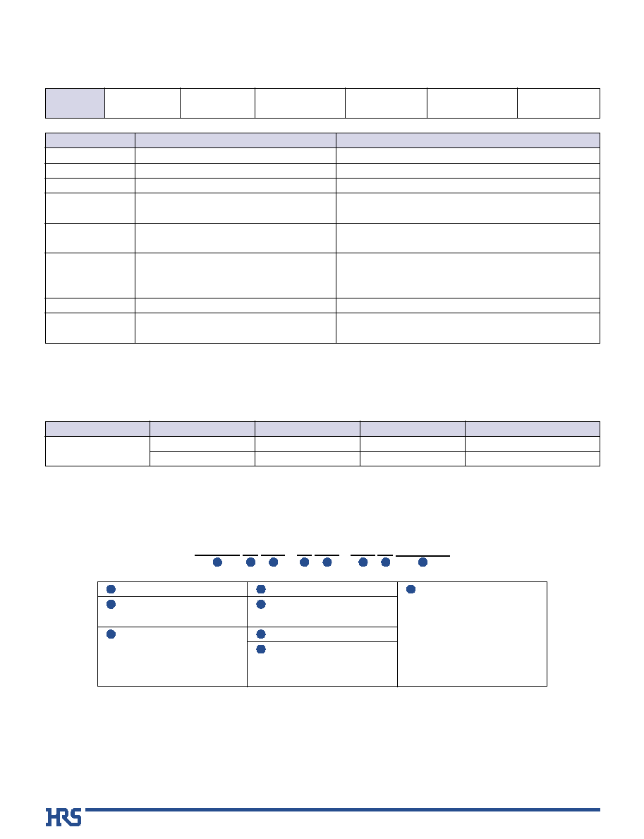
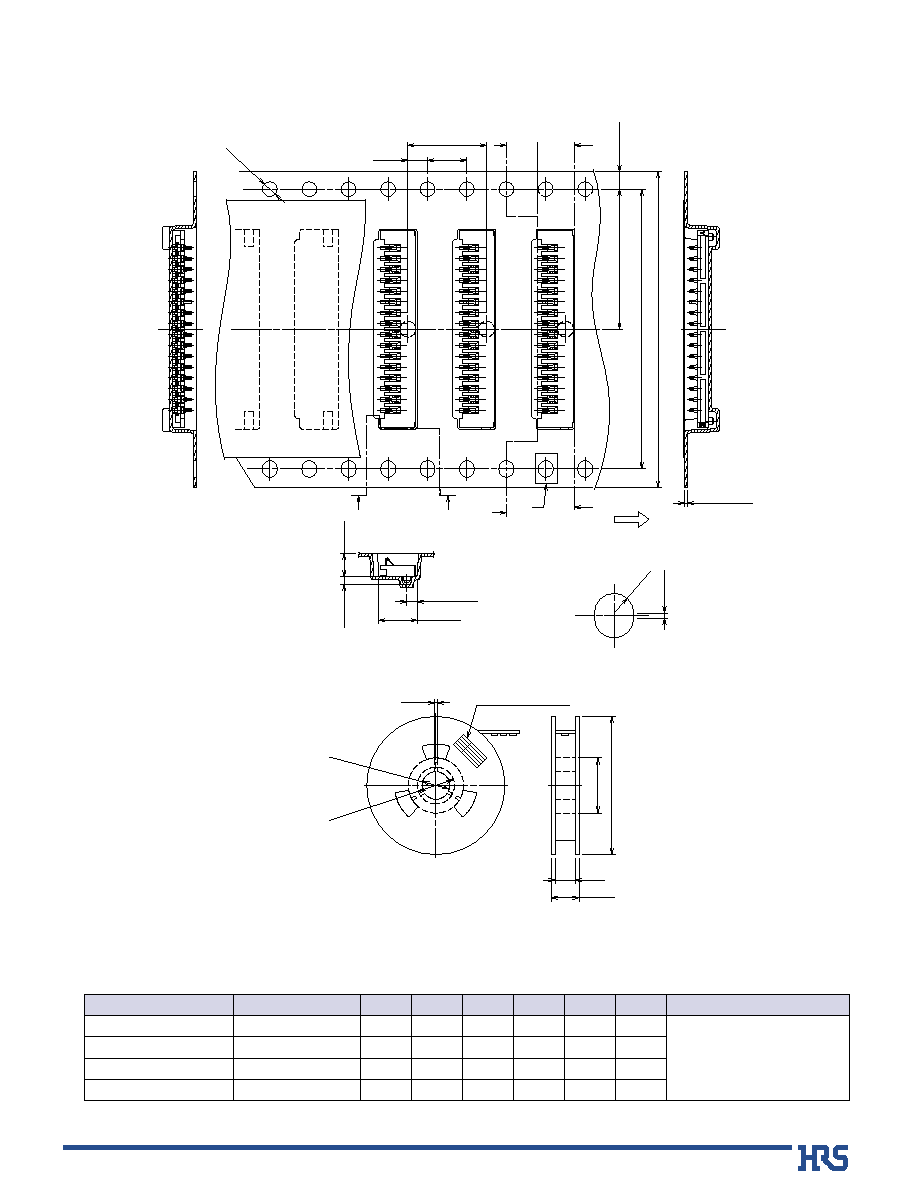
Compression Connectors (Straight SMT) for 1.2mm Mating
B
PCB Mounting Pattern
P=1.1
±
0.05
B
±
0.05
ÿ
0.8
+0.05
0
(Note)
0.55
±
0.03
1.95
±
0.03
C
±
0.05
3
+0.1
0
Connector Mounting Surface Side
0.8
±
0.03
P=1.1
±
0.05
1.3
±
0.2
1.7
+0.1
0
Gold plating
B
±
0.05
Boss hole of mounting board side
Connector Contact Side
Product No.
DF26A1.2-
0
9CP-1.1V(
**
)
DF26A1.2-16CP-1.1V(
**
)
DF26A1.2-18CP-1.1V(
**
)
CL661-0002-5-
**
CL661-0003-8-
**
Under development
0
9
16
18
HRS No.
Number of Contacts.
12.3
20.0
22.2
A
0
8.8
16.5
18.7
B
11.0
18.7
20.9
C
24
32
32
Embossed width
With boss
Notes
[Specification number] ----
* *
, (
* *
)
(51): Gold plating, embossed tape packaging (2,000 pieces per reel)
Note: Order by number of reels.
Unit: mm
4
A
±
0.3
0.35
±
0.05
3.6
±
0.3
1.6
+0.2
≠0.1
B
±
0.2
P=1.1
±
0.1
0.3
±
0.05
2.4
±
0.1
1.97
±
0.1
Boss (Note)
C
±
0.15
ÿ
0.7
≠0.1
1.7
MAX
0.54
0
≠0.1
2.7
±
0.2
0.9
±
0.1
0
Cross-sectional Diagram
Condition at full stroke
2.23 ±0.2
0.12
±0.05
( 0.6 )
s
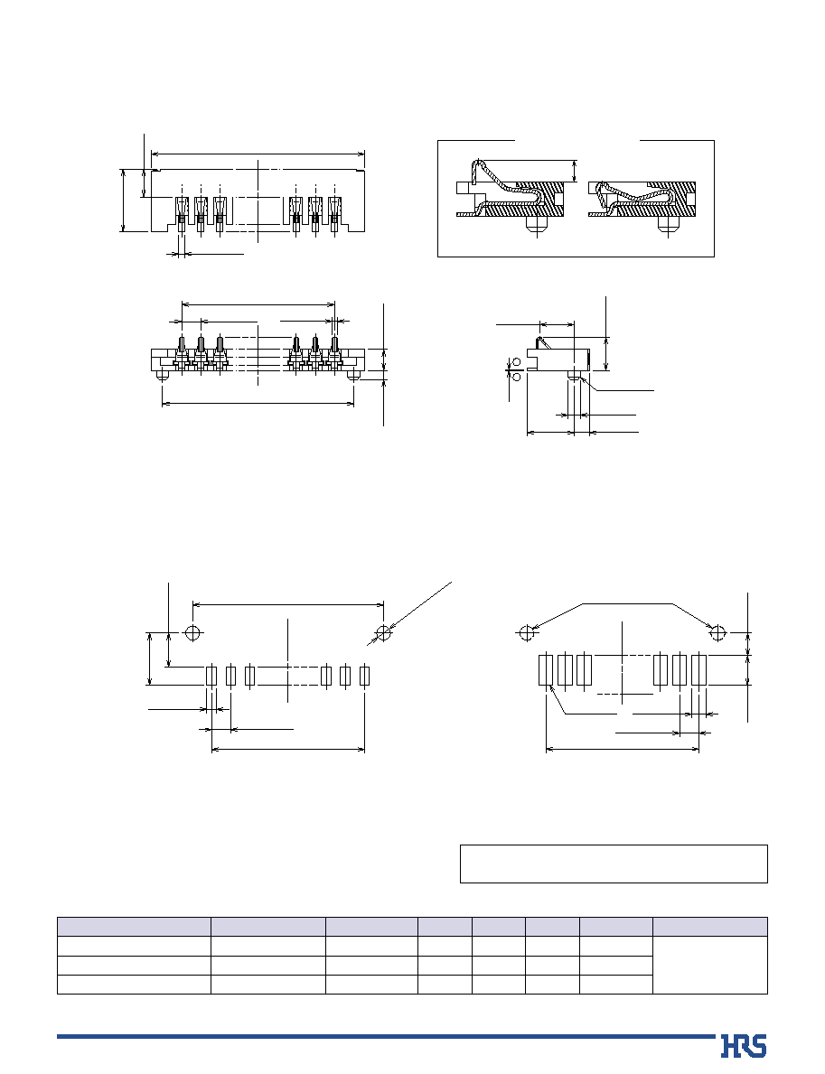
Compression Connectors (Straight SMT) for 1.7mm Mating
B
PCB Mounting Pattern
P=1.1
±
0.05
B
±
0.05
ÿ
0.8
+0.05
0
(Note)
0.55
±
0.03
1.95
±
0.03
C
±
0.05
3
+0.1
0
Connector Mounting Surface Side
0.8
±
0.03
P=1.1
±
0.05
1.3
±
0.2
1.7
+0.1
0
Gold plating
B
±
0.05
Boss hole of mounting board side
Connector Contact Side
Product No.
DF26A1.7- 9CP-1.1V
(
**
)
CL661-0008-1-
**
9
HRS No.
Number of Contacts
12.3
8.8
11.0
24
A
B
C
Embossed width
With boss
Notes
[Specification number] ----
* *
, (
* *
)
(66): Gold plating, embossed tape packaging (2,000 pieces per reel)
Note: Order by number of reels.
Unit: mm
5
*
Under development
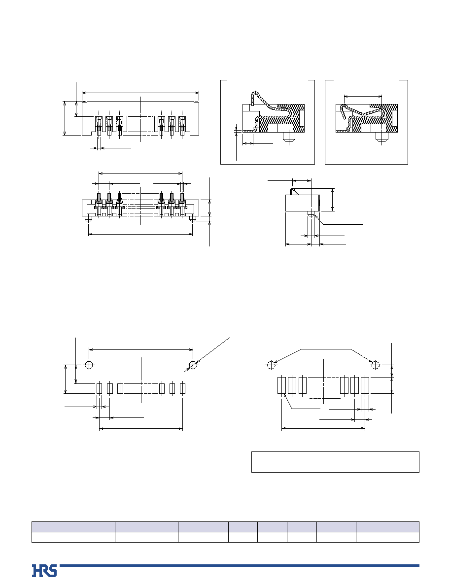
B
Embossed Carrier Tape Dimensions
B
±0.1
4 ±0.1
ÿ1.5
+0.05
0
1.75
±0.1
C
±0.1
A
±0.3
2 ±0.1
8 ±0.1
D
±0.2
0.8
±0.2
t= 0.3 ±0.05
3.9 ±0.2
1.05 ±0.15
K
0.2
±0.05
R0.75
+
0.05
0
H-H
H
J
Unreeling direction
G-G
J-J
G
G
J
K
H
E
+2
0
(
ÿ80
)
ÿ330
±2
ÿ21
±0.8
ÿ13±0.2
2±0.5
Product name label
ÿ1.5
feed hole depth
F MAX
Reel Dimension
Product No.
DF26A1.2-
0
9CP-1.1V
DF26A1.2-16CP-1.1V
DF26A1.2-18CP-1.1V
DF26A1.7-
0
9CP-1.1V
*
0
9
16
18
0
9
24
32
32
24
Number of Contacts
A
----------
28.4
28.4
----------
B
11.5
14.2
14.2
11.5
C
2.4
2.4
2.4
2.9
D
24.4
32.4
32.4
24.4
E
30.4
38.4
38.4
30.4
Unit: mm
F
With boss
Notes
6
B
Precautions for Use
s
Excessive twisting when mating/un-mating may cause damage to the connector.
s
The contacts are of an exposed design and touching them with bare hands may cause breakdown
of the elements due to contact faults or static electricity.
Manual soldering: 290
±
10
Á
for 3 seconds
0.15mm
Maximum of 0.03mm at the connector center, with both ends of the connector as reference points.
Refer to "Nylon connector Use Handbook".
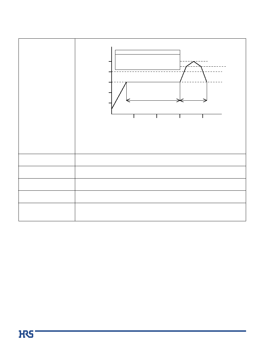
Note1: Up to 2 cycles of reflow soldering are possible under the same conditions, provided that there is a
return to normal temperature between the first and second cycle.
Note2: The temperature profile indicates the board surface temperature at the point of contacts with the
connector terminals (for surface mounted receptacle).
1. Recommended Temperature Profile
6.Precautions
2.Recommended manual soldering
3.Recommended screen thickness
4.Board warpage
5.Cleaning conditions
Temperature
IR Reflow
Preheating:
Preheating
Maximum 240Á
220Á
Soldering
Soldering:
150Á
220Á min
235±5Á
30 to 90 seconds
10 to 30 seconds
10 seconds max
250Á
200Á
150Á
100Á
50Á
0Á
200
Time(Sec.)
150
100
50
0