
B132
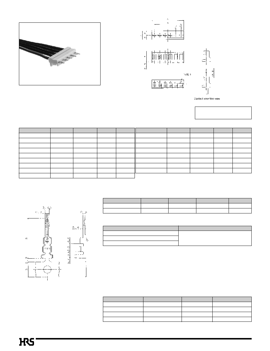
2.5mm Pitch Connector Directly Mounted on Board (Product Compliant to UL/CSA Standard)
DF2 Series
s
Features
1. Header Cost Saving
Based on the harnesses product at the both ends of
insertion/extraction socket and directly mounted connector, the
both socket harnesses can afford to save either of two
necessary headers, while functions to separate mutual boards
are remained.
2. Space Saving
This connector is designed in a narrow space.
Board mounting height :
5.5mm
Width
:
4.0mm
3. Board Pre-fixed Mechanism
Since the connector is smoothly press-fitted to the board, it can be
pre-fixed to the board.
s
Applications
Personal computers, facsimiles, printers and other business
equipment.
Height 5.5mm
Board ground
width 2.7mm
Board pre-fixed
mechanism
Figure 1

B133
s
Product Specifications
Current rating
(Note1)
Voltage rating
AWG 24 : 3A
Cable Size
AWG 26 : 2A
AWG 28 : 1A
250V AC
Storage Temperature Range
Storage Moisture Range
Operating Temperature Range
Operating Moisture Range
-10
to
+60
Á
(Note3)
-
40
to
70
%
(Note3)
-30
to
+85
Á
(Note2)
-
40
to
80
%
s
UL CSA Safety Standard File No.
UL
:E52653
CSA
:LR95109
Item
Specification
Condition
1. Insulation Resistance
1000M
ohms
min.
500V DC
2. Withstanding voltage
No flashover or insulation breakdown.
650V AC/1 minute
3. Resistance in Crimping Area 30m
ohms
Max
100mA
4. Vibration
No damage, cracks, or parts looseness.
Frequency: 10 to 55 Hz, single amplitude of 0.75 mm, 2 hours in each of the 3 directions.
5.
Humidity (Steady state)
Contact resistance: 30m
ohms
max.Insulation resistance: 1000M
ohms
min.
96 hours at temperature of 40Á and humidity of 90% to 95%
6. Temperature Cycle
Contact resistance: 30m
ohms
max:Insulation resistance: 1000M
ohms
min.
(-55
Á
: 30 minutes
5
to
35
Á
: 10 minutes
(-
85
Á
: 30 minutes
5
to
35
Á
: 10 minutes) 5 cycles
7. Resistance to Soldering heat
No deformation of components affecting performance.
Flow: 250Á for 10 seconds
Manual soldering: 300Á for 3 seconds
Rating
s
Material
Product
Part
Material
Finish
Remarks
Crimping Socket
Insulator
Polyamide
White
UL94V-0
Plug Crimping Contact
Contact
Brass
Tin plated
≠≠≠≠≠
Rated Current
Rated Voltage
Wire Size
AWG 24
to
28 : 1A
30V AC
Rating
Standard Value Compliant to UL CSA Safety Standard
Note 1: Includes temperature rise caused by current flow.
Note 2: The term "storage" refers to products stored for long period of time prior to mounting and use. Operating Temperature Range and
Humidity range covers non conducting condition of installed connectors in storage, shipment or during transportation.
s
Ordering Information
q
Crimping Plug
q
Contact
DF2 -
*
P - 2.5 C
q
w e
r
t
DF2 - 2428 - PCF
q
w
q
Series Name
: DF 2
w
Number of Contacts : 2
to
16, 18, 20
e
Connector Type
P : Plug
r
Contact Pitch
: 2.5mm
t
C : Crimping Plug
q
Applicable Cable Size
2428 : AWG 24
to
28
w
Packaging Type
PCF : Plug Contact, Reel
PC : Plug Contact, Bag
B134
s
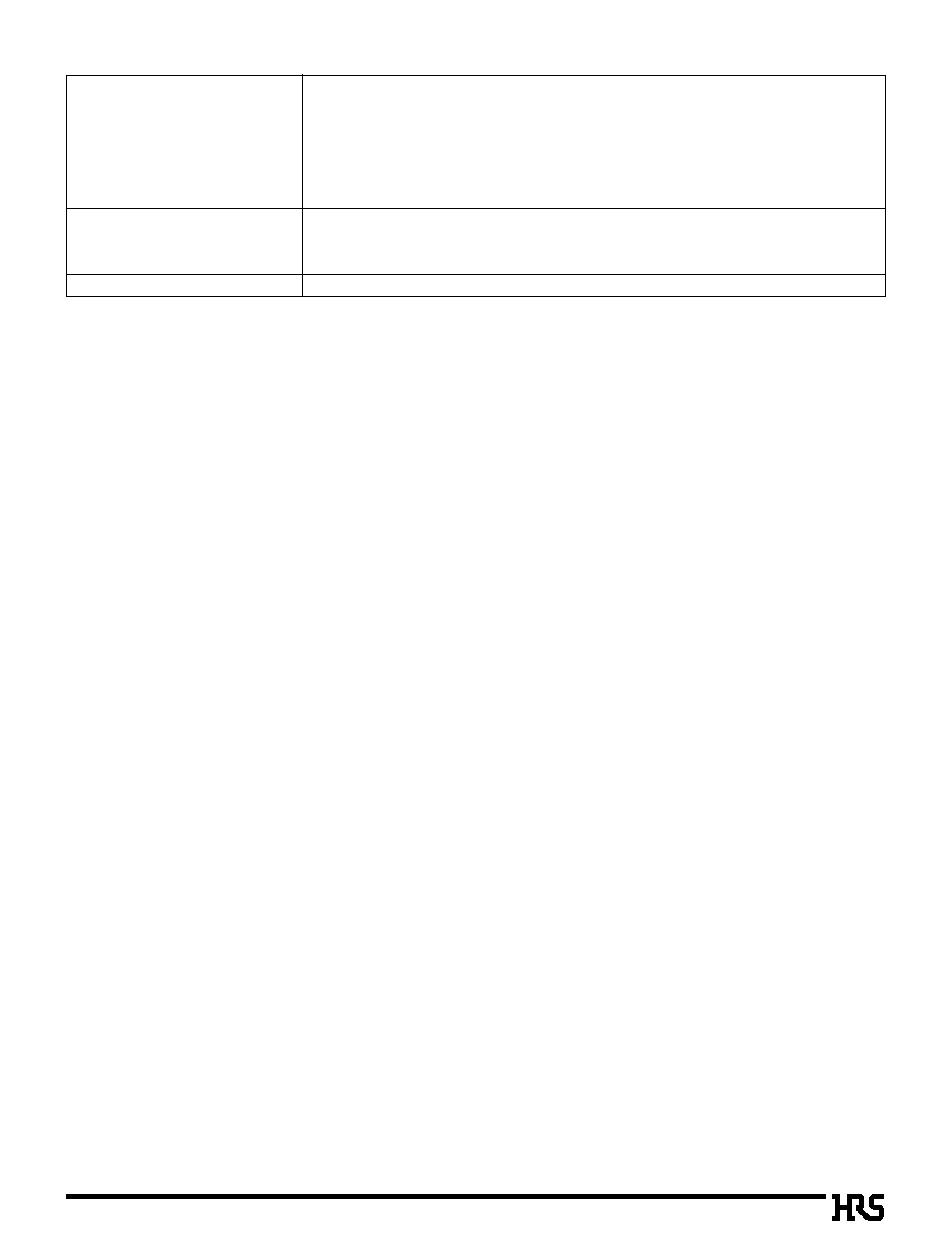
Crimping Plug
s
Crimping Contact
Conductor Size (Wire construction)
Jacket Diameter
AWG #24 (11cores. /0.16mm)
AWG #26 (
0
7cores. /0.16mm)
ÿ
0.9
to ÿ
1.5mm
AWG #28 (
0
7cores. /0.127mm)
q
Applicable Cable (Tin plating annealed copper wire)
Part Number
CL No.
Packaging Type
Quantity
Finish
DF2-2428PCF
542-0020-0
Reel
1000
Tin plated
DF2-2428PC
542-0021-3
Bag
100
Tin plated
q
Recommended Cable
UL1061, UL1007
q
Strip Length
1.6
to
2.1mm
Note: If other cables are used instead of the applicable cable, contact Hirose sales
department.
Photo: Contact Inserted.
B
Applicable Crimping Tool
Type
Part Number
CL No.
Applicable Contact
Applicator
AP105-DF2-2428P
901-4506-1
DF2-2428PCF
Main press unit
CM-105
901-0005-4
---------------
Manual Crimping Tool
DF2-TA2428HC
550-0172-3
DF2-2428PC
Extraction Tool
DF-C-PO(A)
550-0170-8
DF2-2428PCF
Note: If any trouble has occurred due to other tools, which are not designated by Hirose,
Hirose won't guarantee any products.
q
Printed Board Through-hole Diameter :
ÿ0.8
+0.1
+
0
Note1: Contact No. indicates all number of contacts.
Note2: Do not clean the cable with heat nor trichloroethane.
Note : A packaging quantity at the specific No."None" is delivered by the bag unit . If needed, please order the product per bag.
Unit: mm
[Specific No.] ≠
* *
,
(
* *
)
None :100 pcs. per bag
Part Number
CL No.
DF2- 2P-2.5C(
**
)
DF2- 3P-2.5C(
**
)
DF2- 4P-2.5C(
**
)
DF2- 5P-2.5C(
**
)
DF2- 6P-2.5C(
**
)
DF2- 7P-2.5C(
**
)
DF2- 8P-2.5C(
**
)
DF2- 9P-2.5C(
**
)
DF2-10P-2.5C(
**
)
542-0001-6-
**
542-0002-9-
**
542-0003-1-
**
542-0004-4-
**
542-0005-7-
**
542-0006-0-
**
542-0007-2-
**
542-0008-5-
**
542-0009-8-
**
2
3
4
5
6
7
8
9
10
5
7.5
10
12.5
15
17.5
20
22.5
25
2.5
5
7.5
10
12.5
15
17.5
20.5
22.5
Number of Contacts
A
B
Part Number
CL No.
DF2-11P-2.5C(
**
)
DF2-12P-2.5C(
**
)
DF2-13P-2.5C(
**
)
DF2-14P-2.5C(
**
)
DF2-15P-2.5C(
**
)
DF2-16P-2.5C(
**
)
DF2-18P-2.5C(
**
)
DF2-20P-2.5C(
**
)
542-0010-7-
**
542-0011-0-
**
542-0012-2-
**
542-0013-5-
**
542-0014-8-
**
542-0015-0-
**
542-0017-6-
**
542-0019-1-
**
11
12
13
14
15
16
18
20
27.5
30
32.5
35
37.5
40
45
50
25
27.5
30
32.5
35
37.5
42.5
47.5
Number of Contacts
A
B
B135
B
Precautions
1. Recommended Soldering Condition
Flow: 250Á for 3 seconds
Manual soldering: 290Á for 2 seconds
s
After the soldering process, if a load is applied to the cable in the state where the connector
and the cable contains heat, the cable jacket holding members are apt to be loosened.
Therefore, the post-soldering process should be carried out after the connector temperature
returns to the room temperature.
2. Cleaning Condition
Refer to Nylon Connector Use Hand book.
Don't use such a solvent as trichloroethane which degrades the cable jacket.
In addition, avoid heat cleaning with such a solvent.
3. Connection Condition
Refer to Nylon Connector Use Hand book.