
1
SD Memory Card Connectors
DM1 Series
NEW
2003.4
s
Features
1. Withstands higher force of card insertion
Metal cover extends over the back of the connector
allowing it to withstand force of up to 400 N (static load)
when dropped or accidentally hit.
2. No damage to the card when accidentally
pulled-out
The connectors will release the card when a moderate
pull-out force of about 4 N is applied. There will be no
damage to the lock components and all connector
functions will not be affected.
3. Accidental card fall-out prevention
Built-in lock feature holds the card securely in place.
4. Reliable Card Insertion and Withdrawal
Built-in Push-in / Push-out ejection mechanism assures
simple and reliable card insertion and withdrawal.
5. Designed to accept Secure Digital I/O card
(Built-in Ground Contact)
The connector allows use of various expansion modules,
including the Bluetooth communication modules.
s
Applications
Notebook PC's, digital cameras, PDA's, audio/video
equipment and other devices utilizing SD I/O cards.
Card
Standard type
Withstands higher force of card insertion.
Metal cover extends over the back of the connector.
Card
Reverse type
Metal cover extends over the back of the connector.
No damage to the card when
accidentally pulled-out.
Accidental card
fall-out prevention
2
DM
1
AA - SF - PEJ
500 V DC
1000 M ohms min. (Initial value)
1. Insulation resistance
Rating
Current rating 0.5A DC
Voltage rating 125 V AC
Operating temperature range:-25
Á
to +85
Á
(Note 1)
Storage temperature range:-40
Á
to +85
Á
(Note 2)
Operating humidity range : Relative humidity 95%
max. (No condensation)
s
Product Specifications
Item
Specification
Conditions
500 V AC / one minute
No flashover or insulation breakdown
2. Withstanding voltage
100mA DC
100 m ohms max. (Initial value)
3. Contact resistance
Frequency: 10 to 55 Hz, single amplitude of 0.75 mm, 2 hours / 3 axis
No electrical discontinuity of 100 ns or more
4. Vibration
96 hours at temperature of 40
Á ±
2
Á
and
humidity of 90% to 95%
Contact resistance: 40 m ohms max. from initial value
Insulation resistance: 100 M ohms min.
5. Humidity
Temperature: -55Á
/
+5Á to +35Á
/
+85Á
/
+5Á to +35Á
Duration: 30
/
5
/
30
/
5 (Minutes) 5 cycles
Contact resistance: 40 m ohms max. from initial value
Insulation resistance: 100 M ohms min.
6. Temperature cycle
10000 cycles at 400 to 600 cycles per hour
Contact resistance: 40m ohms max. from initial value
7. Durability (mating/un-mating)
Reflow: At the recommended temperature profile
Manual soldering: 300Á for 3 seconds
No deformation of components affecting performance.
8. Resistance to soldering heat
Note1: Includes temperature rise caused by current flow.
Note2: The term "storage" refers to products stored for long period of time prior to mounting and use. Operating Temperature
Range and Humidity range covers non- conducting condition of installed connectors in storage, shipment or during
transportation.
s
Materials
s
Ordering information
1
2
3
4
Component
Material
Finish
Remarks
Insulator
Heat resistant thermoplastic compound
Color: Black
UL94V-0
Contacts
Phosphor bronze
Contact area: Gold plating
Termination area: Tinned copper plating
--------------------
Cover
Stainless steel
Termination area: Tinned copper plating
--------------------
Others
Stainless steel
Piano wire
--------------------
Nickel plating
--------------------
Series name
:
DM1
Connector type
:
AA : Standard receptacle
:
B : Reverse receptacle
Terminal type
SF
: Right angle surface mount
DSF : Reverse right angle surface mount
Eject mechanism codes
PEJ : Card Push insert/Push withdraw
1
2
3
4
3
2
2
1.6±0.05
1.2±0.05
25.4±0.05
15±0.05
4.125±0.05
P=2.5±0.05
9-1.1±0.05
1.35±0.05
1.7±0.05
22.4±0.05
2±0.05
1.2±0.05
23.2±0.05
4.55±0.05
2
+0.1
0
4-2
+0.1
0
2-ÿ1.3
+0.1 0
2
+0.1
0
2
+0.1
0
3-1
+0.1
0
20.75±0.05
18.15±0.05
9.2±0.05
Card detection switch
Write protection switch
9.2
18.15
3-0.5
20.75
No.8
No.7
No.6
No.5
No.4
No.3
No.2
No.1
No.9
1
C
L
1
28
13.2
9.75
8.05
t=0.2,W=0.6
15
5.625
P2.5
1
2.9
22.4
2-ÿ1.2
0.55
30.5
2.5
23.2
4.55
4-1.5
1
C
L
1
1
C
L
1
C
L
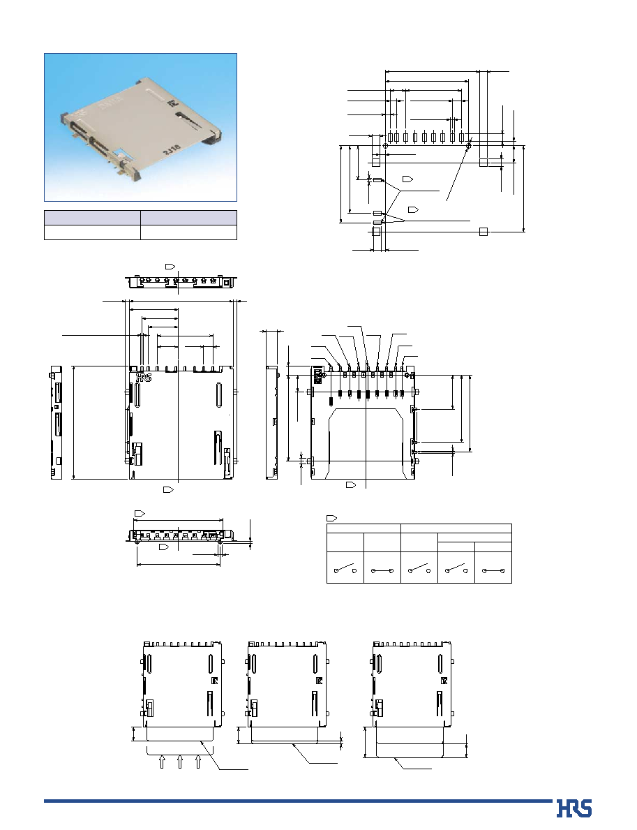
24.15 (Card slot dimension)
Weight:2.2g
When card
is ejected
When card
is ejected
When card
is inserted
When card is inserted
WRITE PROTECT WRITE ENABLE
Card detection switch
Write protection switch
OPEN
CLOSE
OPEN
OPEN
CLOSE
1
C
L
indicates the center line of card slot.
5
1
SD Card
Card pushed-in for insertion
Card fully inserted
Card ejected
(Card ejected dimension)
SD Card
SD Card
5
6
11
s
Standard type
Part number
DM1AA-SF-PEJ(21)
609-0004-8-21
HRS No.
B
PCB mounting pattern
B
Card insertion/withdrawal dimensions
4
A(5:1)
B(5:1)
C(5:1)
(R0.6)
(R0.4)
(R0.6)
(R0.4)
(R0.6)
(R0.4)
1.7
+0.1 0
(Land)
1.2
+0.1
0
(Land)
1.3
+0.1 0
(Through hole)
0.8
+0.1
0
(Through hole)
1.9
+0.1 -0.1
(Land)
1.2
+0.1
0
(Land)
1.5
+0.1 0
(Through hole)
0.8
+0.1
0
(Through hole)
2.4
+0.1 -0.1
(Land)
1.2
+0.1
0
(Land)
2
+0.1 0
(Through hole)
0.8
+0.1
0
(Through hole)
CARD DETECT
COMMON FOR CD & WP
WP
A
A
C
B
5.62
9.47±0.05
12.8±0.05
11.2±0.05
9.75±0.05
0.8±0.05
1.4±0.05
8.05±0.05
12.5±0.05
5.625±0.05
P=2.5±0.05
1.25±0.05
8-1.1±0.05
12.57±0.05
11.23±0.05
14.13±0.05
11.93±0.05
2.03±0.05
1.4±0.05
23.48±0.05
26.98±0.05
28.5±0.05
14.25±0.05
0.8±0.05
11-2.5±0.05
1.05±0.05
28.25±0.05
3
3
Center of Card dimension
s
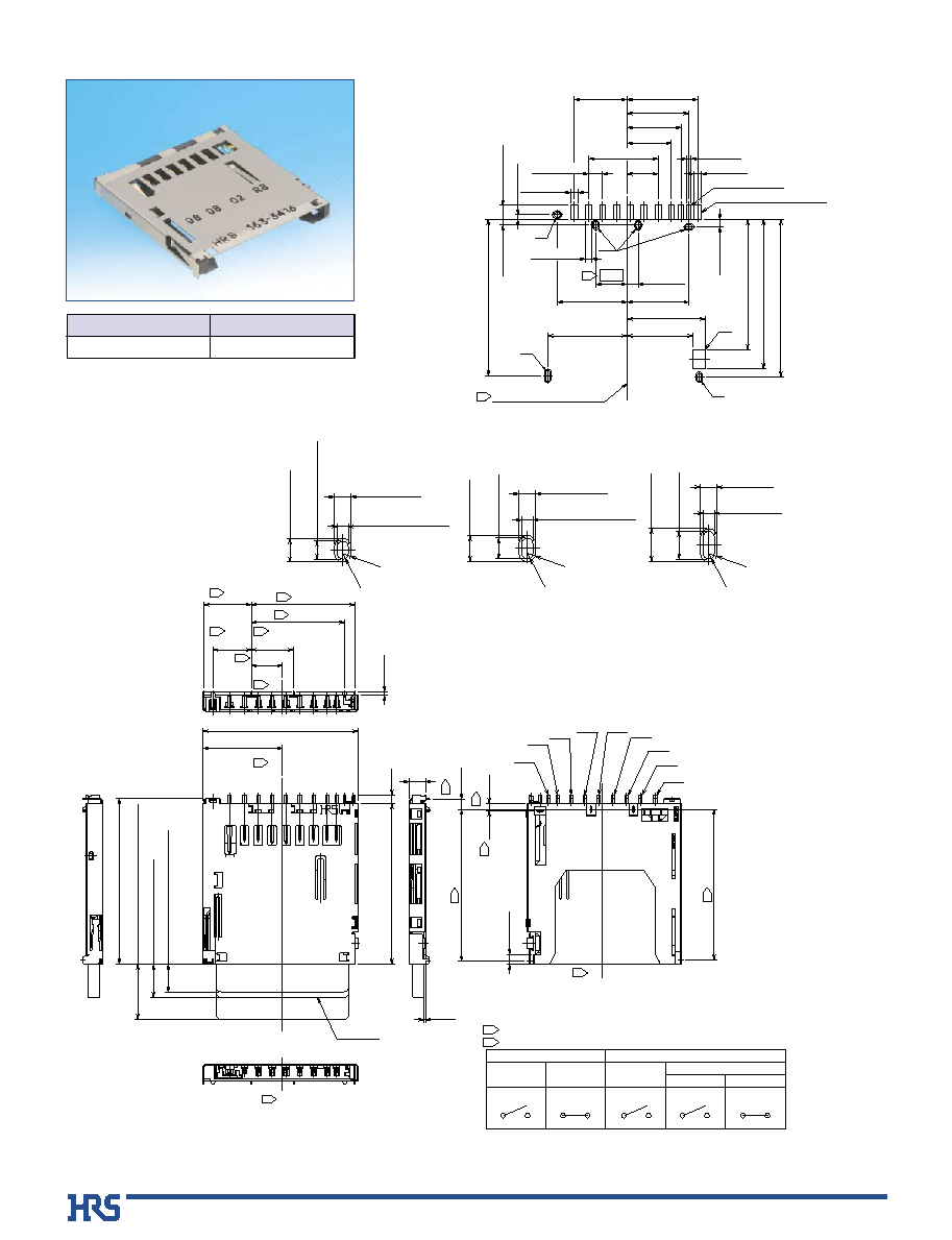
Reverse type
B
PCB mounting pattern
2
(0.25)
(1.77)
No.8
No.7
No.6
No.5
No.4
No.3
No.2
No.1
No.9
28
(14.35)
18.68
2
16.85
6-0.65
1.5
1.85
1.05
0.35
2
2
2
2
2
27.2
2
27.45
29
2
8.63
1
C
L
1
C
L
2
6.95
2
7.65
5.62
2.9
1
C
L
1
C
L
29.9
SD Card
(5):Card pushed for insertion
(6):Card fully inserted
10:
Card ejected(Card ejected dimension)
Weight:2.1g
1
2
When card is ejected
OPEN
OPEN
CLOSE
WRITE PROTECT WRITE ENABLE
Card detection switch
When card
is ejected
When card
is ejected
When card
is ejected
Write protection switch
OPEN
CLOSE
indicates the dimension of DIP terminals.
C
L
indicates the center line of the card slot.
Part number
DM1B-DSF-PEJ
609-0003-5
HRS No.

5
2±0.15
4±0.1
1.75±0.1
ÿ1.5
+0.1
0
36±0.1
3.4±0.3
4.35±0.3
44±0.3
40.4±0.1
20.2±0.1
Unreeling direction
B
Packaging specifications
q
Embossed Carrier Tape Dimensions (Standard type) 450 pieces per reel
2±0.15
4±0.1
36±0.1
4.6±0.3
3.4±0.3
1.75±0.1
44±0.3
40.4±0.1
20.2±0.1
ÿ1.5
+0.1
0
Unreeling direction
q
Embossed Carrier Tape Dimensions(Reverse type) 450 pieces per reel
End section
Blank section(160mm min.)
Mounting section(450)
Lead section (400mm min.)
Blank section (100mm min.)
Embossed carrier tape
Top cover tape
(ÿ380)
(ÿ150)
D
Unreeling direction
44.4
+2
0
q
Reel dimensions