6
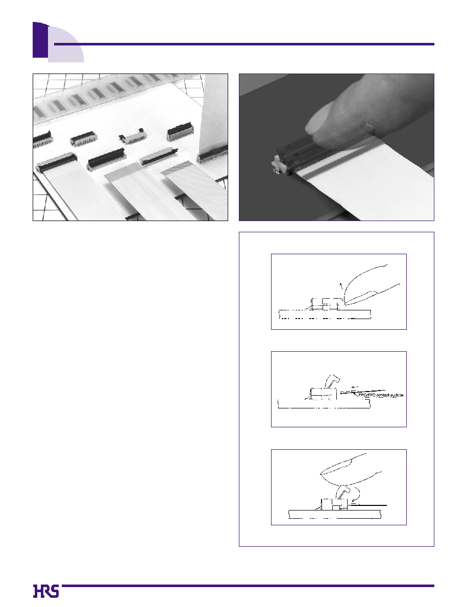
0.5mm and 1mm Pitch Connectors For FPC/FFC
FH12 Series
s
Features
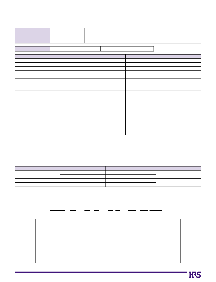
1. Ease of Use and Space Savings
Only one finger or 6.9N (Newtons) of force is required to
lock Hirose's rotational actuator (flip-lock) as compared
to using 2 fingers and 39.2N to close a FFC/FPC
connector from our competition.
The Flip-Lock design also allows customers to place 2
or more connectors side by side as there is no need to
waste additional board space for a side latch.
2. Strengthened Flip-lock Actuator
The standard Flip-Lock requires only 2.0mm height
above the board. A strengthened lock lever is available
which only requires an additional 0.4mm.
3. Supports Thin FPC (0.18mm)
Hirose does not require double-sided FPC to have any
additional strengthening plate or stiffener and can therefore
support a thickness of as little as 0.18mm +/- 0.05.
4. Hirose Ensures Reliability
Hirose's patented half tuning fork contacts maintain the
required normal force without relying on the connector
housing. With our competitor's conventional products
the housing walls support the contact force, which does
not provide for long-term reliability.
5. Prevention of Solder Bridge
Excess solder cavity absorbs excessive solder and
avoids solder bridging.
6. Three different assembly types
FH12 is offered in Top & Bottom Contact and Vertical
Mount and offered in both a 0.5mm contact pitch as well
as a 1.0mm contact pitch (bottom contact only).
s
Applications
Notebook computers, printers, PDAs, digital cameras and
other compact devices for interconnecting the main circuit
board with the LCD, HDD or other device.
Rotating One-touch Mechanism
q
w
e
Flip-lock
7
s
Product Specifications
Rating
Current rating: 0.4A DC Operating Temperature Range:_40 to +70Á (Note 1) Storage Temperature Range:_10 to +50Á (Note 2)
Voltage rating: 50V AC
Operating Humidity Range:Relative humidity, 90% max. Storage Humidity Range:Relative humidity, 90% max.
(Not dewed)
(Not dewed)
Applicable FPC
t=0.3±0.05
Tin-lead
plating(Note 3)
t=0.18 ± 0.05 for FH12F-*S-0.5SH
Note 1: Includes temperature rise caused by current flow.
Note 2: The term "storage" refers to products stored for long period of time prior to mounting and use. Operating Temperature Range and
Humidity range covers nonconducting condition of installed connectors in storage, shipment or during transportation.
Note 3: When FPC is gold plated, the connector contacts should be also gold plated: Select the (05) specification.
s
Material
Part
Material
Finish
Remarks
Insulator
Polyamide
Color : Beige
UL94V-0
PPS
Color : Dark brown
Contact
Phosphor bronze
Tin-lead
plating
≠≠≠≠≠≠≠
Macal Fittings
Brass
Tin-lead
plating
s
Ordering Information
FH12 A - 10 (4) - S A - 0.5 SH (05)
q
e
r
w
y
t
u
i
o
q
Series Name
: FH12
w
Blank : standard type
A : Top contact type
S : Type with strengthed flip-lock actuator
F : Type with 0.18mm FPC End Thickness
e
Standard type
: Number of contacts
Eccentric type
: Number of contacts in 0.5mm housing
r
Standard type
: Blank
Eccentric type
: Number of contacts
t
Contact alignment: Single
y
Eccentric direction:
Blank : standard type
A : Eccentric type
u
Contacts Pitch
: 0.5mm, 1mm
i
Contact type
SH : SMT horizontal mounting type
SV : SMT vertical mounting type
Plating specification
Blank :
Tin-lead
plating
(05) : Gold plating
o
1. Insulation resistance
500M ohms minimum
100V DC
2. Withstanding voltage
No flashover or insulation breakdown.
150V AC/1 minute
3. Contact resistance
50m ohms maximum
1mA
4. Durability (Insertion/withdrawal)
Contact resistance: 50m ohms maximum
20 cycles
No damage, cracks, or parts dislocation.
No electrical discontinuity of 1µs or more
Frequency: 10 to 55 Hz, single amplitude of 0.75 mm,
5. Vibration
Contact resistance: 50m ohms maximum.
2 hours in each of the 3 directions.
No damage, cracks, or parts dislocation.
No electrical discontinuity of 1µs or more
Acceleration of 490 m/s
2
, 11 ms duration,
6. Shock
Contact resistance: 50m ohms maximum.
sine half-wave waveform, 3 cycles in each of the 3 axis.
No damage, cracks, or parts dislocation.
Contact resistance: 50m ohms maximum.
7. Humidity(Steady state) Insulation resistance: 50M ohms minimum.
96 hours at temperature of 40Á and humidity of 90% to 95%
No damage, cracks, or parts dislocation.
Contact resistance: 50m ohms maximum.
5 cycles under conditions as follows;
8. Temperature Cycle
Insulation resistance: 50M ohms minimum.
Temperature: -40Á / 15 to 35Á / 85Á / 15 to 35Á,
No damage, cracks, or parts dislocation.
Time: 30 / 5 max. / 30 / 5 max.(minutes)
9.Resistance to Soldering heat
No deformation of
Reflow: At the recommended temperature profile
components affecting performance.
Manual soldering: 350±5Á for 3 seconds
Item
Specification
Conditions
8
B
Series Configuration
FH12-
**
S-0.5SH
Number of contacts 6, 10, 11, 12, 13, 14,
15, 16, 17, 18, 19, 20,
22, 24, 25, 26, 28, 30,
32, 33, 34, 36, 40, 45,
50, 53
FH12F-
**
S-0.5SH
Number of contacts 6, 10, 12, 13, 14, 15, 16,
18, 20, 22, 24, 26, 28,
30, 32, (33), 34, 36, 40
FH12S-
**
S-0.5SH
Number of contacts 30, 40, 45, 50, 53
Standard
FH12-
**
S-1SH
Eccentric
FH12-
**
(
**
)
S-1SH
Standard
Number of contacts
5, 6, 7, 8, 9, 11,
16, 22, 26
Eccentric
Number of contacts
4, 6, 8, 10, 11,
14, 19, 24
FH12-
**
S-1SV
Number of contacts
6, 7, 8, 16, 20, 22,
24
Pitch
0.5mm
1mm
Bottom Contact Type
Type with Strengthened Lock Lever
Type with 0.18mm FPC End Thickness
Top Contact Type
Vertical mounting Type
P.13
P.12
P.14
P.18
P.19
FH12-
**
S-0.5SV
Number of contacts 10, 12, 13, 15, 16, 17,
18, 20, 22, 24, 26, 30,
32, 33, 34, 36, 40, 45,
49, 50
P.16
FH12A-
**
S-0.5SH
Number of contacts 10, 12 ,15, 16, 18, 20,
22, 24, 26, 28, 29, 30,
32, 33, 34, 36, 40, 42,
45, 50
P.15
FPC conductive
surface
FPC conductive surface
(bottom side)
FPC conductive surface
(bottom side)
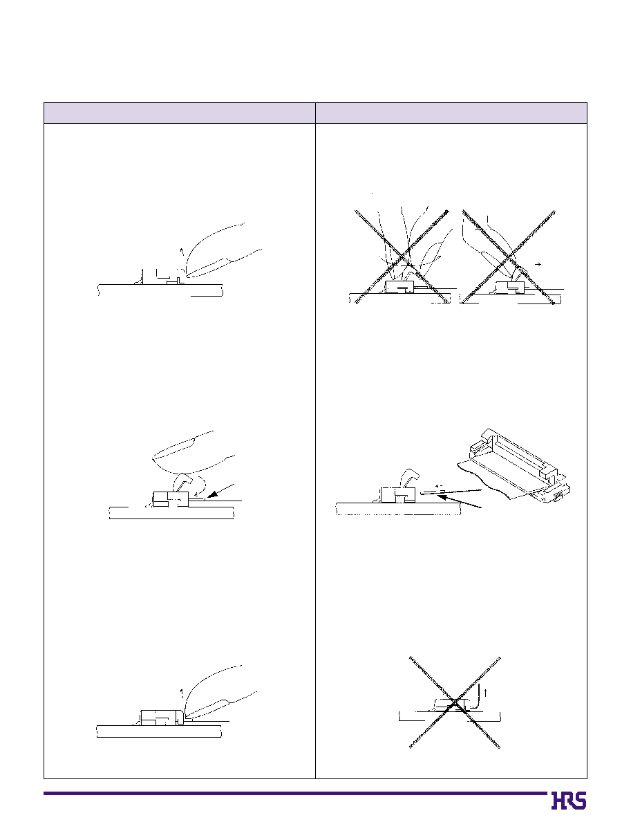
Operation
Precautions
9
B
Connector Operating Instructions, precautions and recommendations
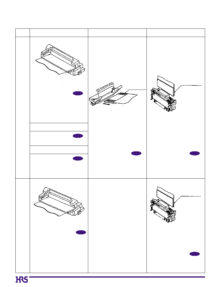
q
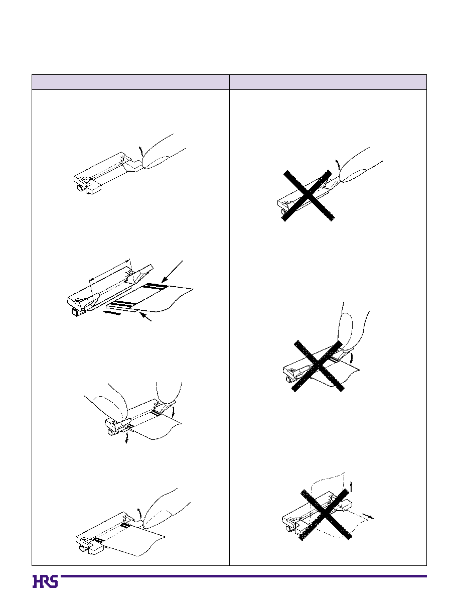
Bottom Contact Type (common for 0.5mm/1mm)
1. FPC/FFC Termination procedure.
Connector installed on the board.
1) Lift up the actuator. Use thumb or index finger.
1) Avoid grasping the actuator with two fingers or lift-
ing the actuator with fingernail.
2) Rotate down the actuator until firmly closed.
It is critical that the inserted FPC/FFC is not moved
and remains fully inserted. Should the FPC/FFC be
moved, open the actuator and repeat the process,
starting with Step 1 above.
2) Fully insert the FPC/FFC parallel to mounting sur-
face, with the exposed conductive traces facing
down.
2. FPC/FFC Removal
1) Lift up the actuator.
2) Carefully remove the FPC/FFC.
3) Due to the structure of the connectors, they do
not have strong resistance to upward pulling;
therefore, support the FPC/FFC when a pulling
force is applied to it.
Stiffener
FPC/FFC conductive traces
10
q
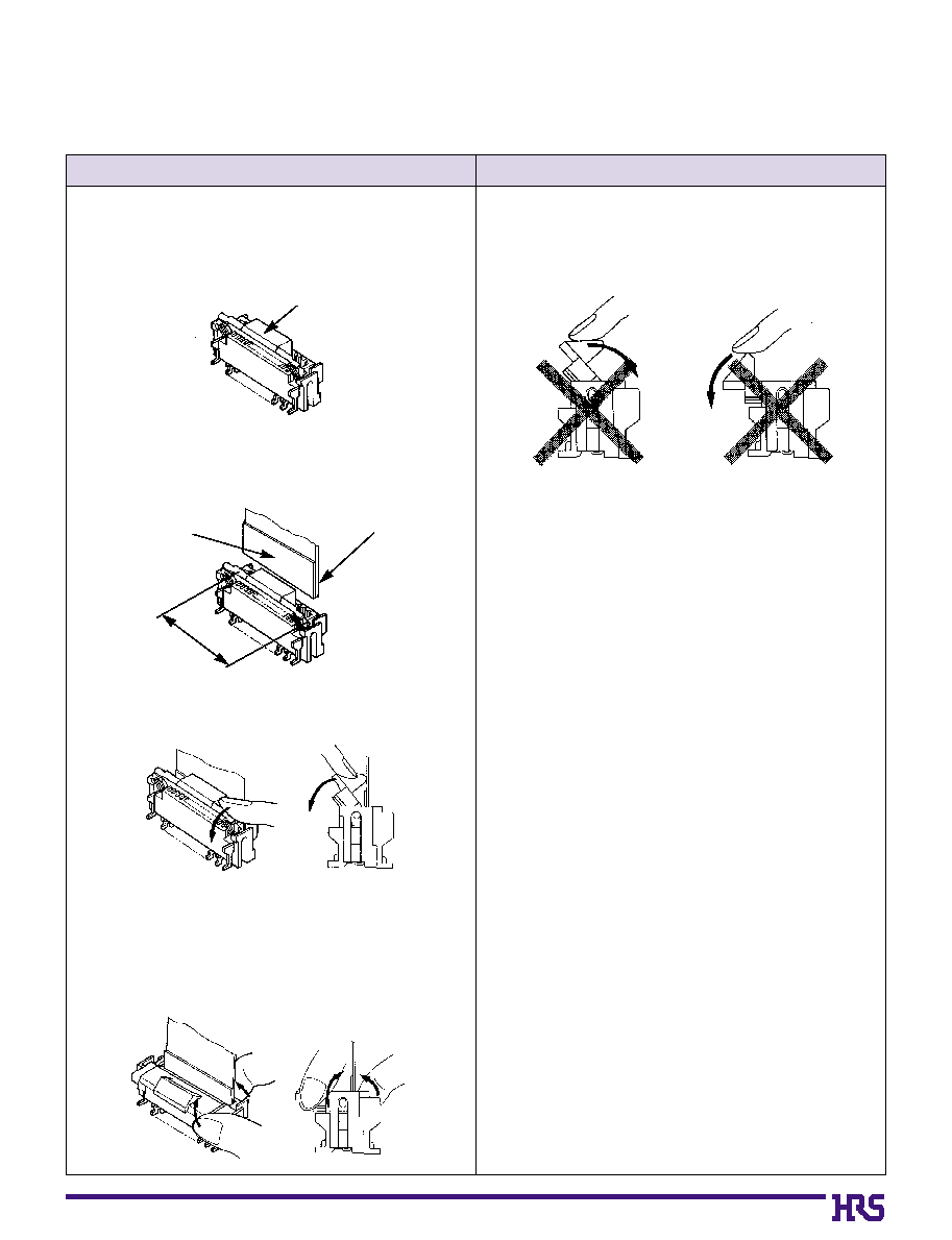
Top Contact Type
Operation
Precautions
1. FPC/FFC Termination procedure.
Connector installed on the board.
1) Lift up the actuator. Use thumb or index finger.
2) Fully insert the FPC/FFC parallel to mounting sur-
face, with the exposed conductive traces facing
UP.
3) Rotate down the actuator until firmly closed.
It is critical that the inserted FPC/FFC is not moved
and remains fully inserted. Should the FPC/FFC be
moved, open the actuator and repeat the process,
starting with Step 1 above.
2. FPC/FFC Removal
1) Lift up the actuator.
2) Carefully remove the FPC/FFC.
FPC/FFC conductive traces
Stiffener
FPC insertion area
1) Avoid forcing the actuator up or down without the
FPC/FFC inserted.
2) When closing down the actuator apply equal pres-
sure to both sides of the actuator.
3) Avoid forced pulling of the FPC. Forced pulling
will cause the FPC to become disconnected or
damaged.
11
q
Vertical Mounting Type
Operation
Precautions
1. FPC/FFC Termination procedure.
Connector installed on the board.
1) Verify that the actuator is positioned upright. If the
actuator has rotated to the side, carefully rotate it
upright.
2) Insert the FPC/FFC vertically in the connector slot
assuring that the conductive traces of the
FPC/FFC are facing away from the actuator.
3) Press down the actuator in the direction shown.
2. FPC/FFC Removal
Rotate the actuator upward and withdraw the
FPC/FFC.
1) Avoid forcing the actuator up or down without the
FPC/FFC inserted.
FPC/FFC conductive traces
Actuator upright
Stiffener
Slot

12
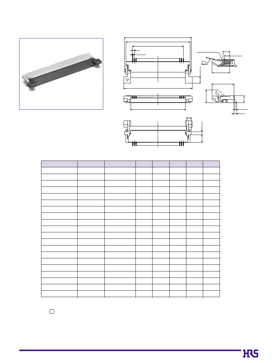
s
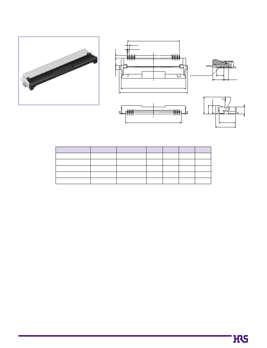
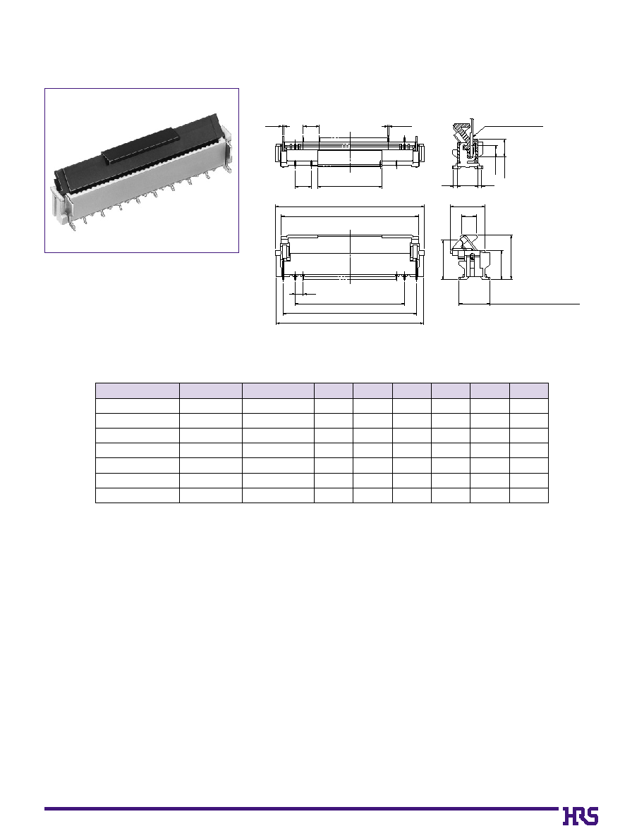
0.5mm Pitch Bottom Contact Type
2
0.2
0.5
0.8
2
1.2
1.85
5.6
4.6
4.8
2
FPC/FFC Contact Surface
1.3
2.1
3.1
Mated Cross-sectional Diagram
Note 1 : Embossed tape reel packaging (2,000 pieces/reel).
Order by number of reels.
Note
: If there is no problem with the connector height, we recommend the type with the
strengthened Flip-lock actuator (FH12S-
*
S-0.5SH).
Standard type connector height: 2 mm
Connector height of type with strengthened Flip-lock actuator: 2.4 mm
D
Unit:mm
CL No.
Part Number
586-0582-5
586-0522-3
586-0600-5
586-0704-0
586-0549-0
586-0533-0
586-0523-6
586-0531-4
586-0606-1
586-0530-1
586-0534-2
586-0524-9
586-0532-7
586-0521-0
586-0692-3
586-0576-2
586-0612-4
586-0525-1
586-0681-7
586-0520-8
586-0617-8
586-0526-4
586-0527-7
586-0528-0
586-0529-2
586-0595-7
FH12-
0
6S-0.5SH
FH12-10S-0.5SH
FH12-11S-0.5SH
FH12-12S-0.5SH
FH12-13S-0.5SH
FH12-14S-0.5SH
FH12-15S-0.5SH
FH12-16S-0.5SH
FH12-17S-0.5SH
FH12-18S-0.5SH
FH12-19S-0.5SH
FH12-20S-0.5SH
FH12-22S-0.5SH
FH12-24S-0.5SH
FH12-25S-0.5SH
FH12-26S-0.5SH
FH12-28S-0.5SH
FH12-30S-0.5SH
FH12-32S-0.5SH
FH12-33S-0.5SH
FH12-34S-0.5SH
FH12-36S-0.5SH
FH12-40S-0.5SH
FH12-45S-0.5SH
FH12-50S-0.5SH
FH12-53S-0.5SH
Number of Contacts
6
10
11
12
13
14
15
16
17
18
19
20
22
24
25
26
28
30
32
33
34
36
40
45
50
53
A
B
0
2.5
0
4.5
0
5
.0
0
5.5
0
6
.0
0
6.5
0
7
.0
0
7.5
0
8
.0
0
8.5
0
9
.0
0
9.5
10.5
11.5
12
.0
12.5
13.5
14.5
15.5
16
.0
16.5
17.5
19.5
22
.0
24.5
26
.0
0
6.1
0
8.1
0
8.6
0
9.1
0
9.6
10.1
10.6
11.1
11.6
12.1
12.6
13.1
14.1
15.1
15.6
16.1
17.1
18.1
19.1
19.6
20.1
21.1
23.1
25.6
28.1
29.6
C
0
7.1
0
9.1
0
9.6
10.1
10.6
11.1
11.6
12.1
12.6
13.1
13.6
14.1
15.1
16.1
16.6
17.1
18.1
19.1
20.1
20.6
21.1
22.1
24.1
26.6
29.1
30.6
0
3.57
0
5.57
0
6.07
0
6.57
0
7.07
0
7.57
0
8.07
0
8.57
0
9.07
0
9.57
10.07
10.57
11.57
12.57
13.07
13.57
14.57
15.57
16.57
17.07
17.57
18.57
20.57
23.07
25.57
27.07
2
2
2
2
2
Note
Note
Note
Note
Note
2
13
Note: Embossed tape reel packaging (2,000 pieces/reel).
Order by number of reels.
D
Unit:mm
CL No.
Part Number
586-0667-6
586-0640-0
586-0665-0
586-0642-5
586-0691-0
FH12S-30S-0.5SH
FH12S-40S-0.5SH
FH12S-45S-0.5SH
FH12S-50S-0.5SH
FH12S-53S-0.5SH
Number of Contacts
30
40
45
50
53
A
B
14.5
19.5
22.0
24.5
26.0
18.1
23.1
25.6
28.1
29.6
C
19.1
24.1
26.6
29.1
30.6
15.57
20.57
23.07
25.57
27.07
s
0.5mm Pitch Bottom Contact Type with Strengthened Flip-lock Actuator
FPC/FFC Contact Surface
Mated Cross-sectional Diagram
2
C
B
1.2
2
0.8
0.2
0.5
A
(4.8
)
2.1
3.1
1.3
2.25
2.4
D
4.6
5.6
(
)
(
)
(
)
(
)
14
Applicable FPC end thickness : 0.18
±
0.05
s
0.5mm Pitch Bottom Contact Type with 0.18mm FPC End Thickness
0.2
0.5
A
0.8
2
1.2
B
C
D
1.85
2
5.6
4.6
4.8
FPC Contact Surface
3.15
2.15
1.25
Mated Cross-sectional Diagram
(
)
(
)
(
)
(
)
()
Note: Embossed tape reel packaging (2,000 pieces/reel).
Order by number of reels.
D
Unit:mm
CL No.
Part Number
586-0672-6
586-0709-4
586-0653-1
586-0629-7
586-0655-7
586-0680-4
586-0673-9
586-0626-9
586-0636-2
586-0630-6
586-0632-1
586-0627-1
586-0643-8
586-0628-4
586-0705-3
--------------------
586-0677-0
586-0656-0
586-0635-0
FH12F-
0
6S-0.5SH
FH12F-10S-0.5SH
FH12F-12S-0.5SH
FH12F-13S-0.5SH
FH12F-14S-0.5SH
FH12F-15S-0.5SH
FH12F-16S-0.5SH
FH12F-18S-0.5SH
FH12F-20S-0.5SH
FH12F-22S-0.5SH
FH12F-24S-0.5SH
FH12F-26S-0.5SH
FH12F-28S-0.5SH
FH12F-30S-0.5SH
FH12F-32S-0.5SH
FH12F-33S-0.5SH
FH12F-34S-0.5SH
FH12F-36S-0.5SH
FH12F-40S-0.5SH
Number of Contacts
6
10
12
13
14
15
16
18
20
22
24
26
28
30
32
33
34
36
40
A
B
0
2.5
0
4.5
0
5.5
0
6.0
0
6.5
0
7.0
0
7.5
0
8.5
0
9.5
10.5
11.5
12.5
13.5
14.5
15.5
16.0
16.5
17.5
19.5
0
6.1
0
8.1
0
9.1
0
9.6
10.1
10.6
11.1
12.1
13.1
14.1
15.1
16.1
17.1
18.1
19.1
19.6
20.1
21.1
23.1
C
0
7.1
0
9.1
10.1
10.6
11.1
11.6
12.1
13.1
14.1
15.1
16.1
17.1
18.1
19.1
20.1
20.6
21.1
22.1
24.1
0
3.57
0
5.57
0
6.57
0
7.07
0
7.57
0
8.07
0
8.57
0
9.57
10.57
11.57
12.57
13.57
14.57
15.57
16.57
17.07
17.57
18.57
20.57
15
D
E
Unit:mm
CL No.
Part Number
586-0550-9
586-0696-4
586-0551-1
586-0552-4
586-0553-7
586-0554-0
586-0686-0
586-0555-2
586-0663-5
586-0725-0
586-0585-3
586-0556-5
586-0687-3
586-0570-6
586-0670-0
586-0662-2
586-0557-8
586-0698-0
586-0558-0
586-0559-3
FH12A-10S-0.5SH
FH12A-12S-0.5SH
FH12A-15S-0.5SH
FH12A-16S-0.5SH
FH12A-18S-0.5SH
FH12A-20S-0.5SH
FH12A-22S-0.5SH
FH12A-24S-0.5SH
FH12A-26S-0.5SH
FH12A-28S-0.5SH
FH12A-29S-0.5SH
FH12A-30S-0.5SH
FH12A-32S-0.5SH
FH12A-33S-0.5SH
FH12A-34S-0.5SH
FH12A-36S-0.5SH
FH12A-40S-0.5SH
FH12A-42S-0.5SH
FH12A-45S-0.5SH
FH12A-50S-0.5SH
Number of Contacts
10
12
15
16
18
20
22
24
26
28
29
30
32
33
34
36
40
42
45
50
A
B
9.1
10.1
11.6
12.1
13.1
14.1
15.1
16.1
17.1
18.1
18.6
19.1
20.1
20.6
21.1
22.1
24.1
25.1
26.6
29.1
8.35
9.35
10.85
11.35
12.35
13.35
14.35
15.35
16.35
17.35
17.85
18.35
19.35
19.85
20.35
21.35
23.35
24.35
25.85
28.35
C
4.5
5.5
7.0
7.5
8.5
9.5
10.5
11.5
12.5
13.5
14.0
14.5
15.5
16.0
16.5
17.5
19.5
20.5
22.0
24.5
9.5
10.5
12.0
12.5
13.5
14.5
15.5
16.5
17.5
18.5
19.0
19.5
20.5
21.0
21.5
22.5
24.5
25.5
27.0
29.5
5.57
6.57
8.07
8.57
9.57
10.57
11.57
12.57
13.57
14.57
15.07
15.57
16.57
17.07
17.57
18.57
20.57
21.57
23.07
25.57
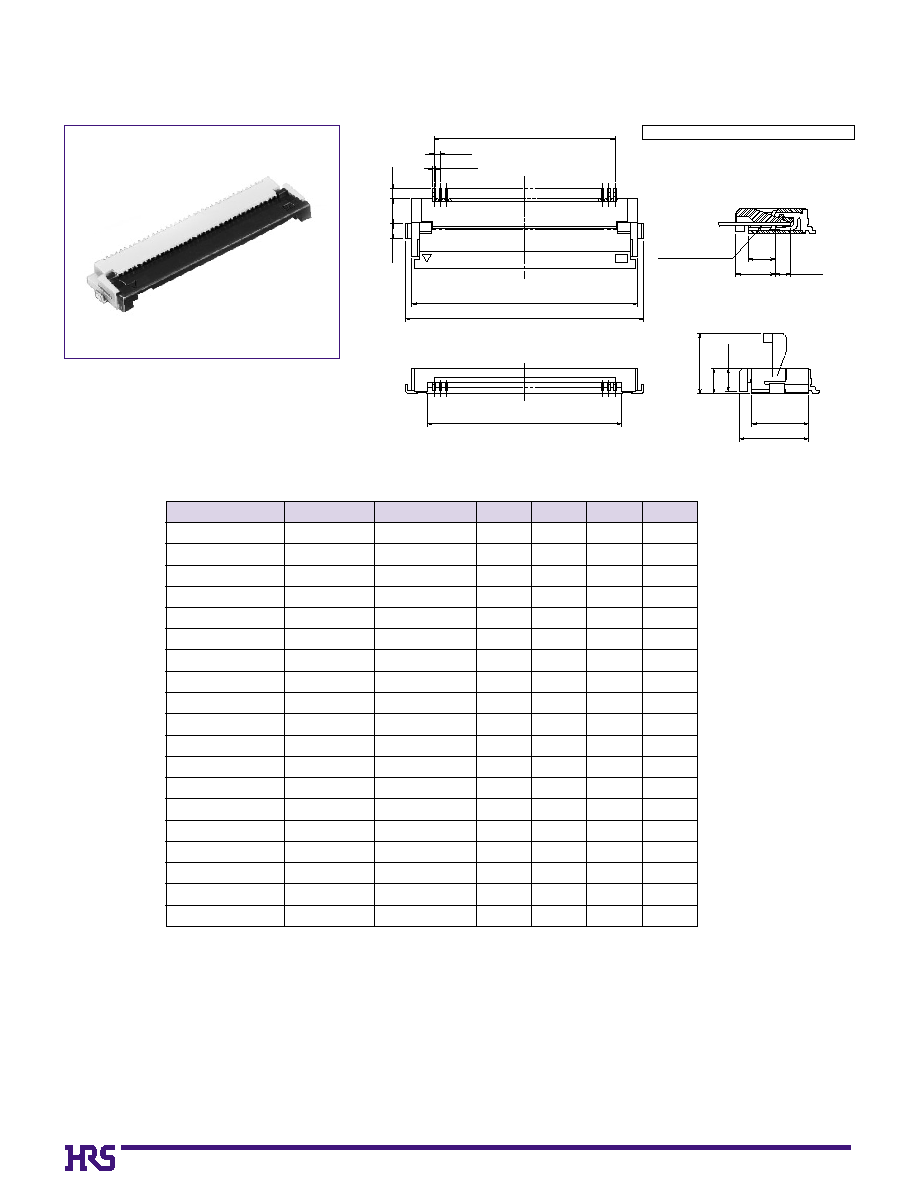
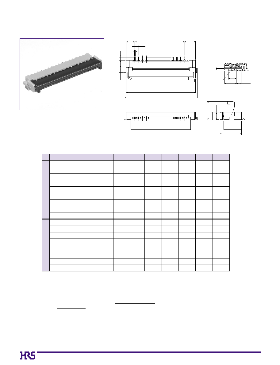
s
0.5mm Pitch Top Contact Type
0.5
2.2
0.85
0.8
1.45
6.2
2
2
FPC/FFC Contact Surface
Mated Cross-sectional Diagram
(1.45)
(1.9)
(5)
(0.45)
(1.85)
(3.6)
(0.2)
A
B
C
D
E
Note 1 : Embossed tape reel packaging (2,000 pieces/reel).
Order by number of reels.
Note
: The design is such that the FPC/FFC protrudes on an upward angle so that other
parts can be mounted beneath the PFC/FFC. In view of this, please take note of the
gap at the top surface of the connector.
2
16
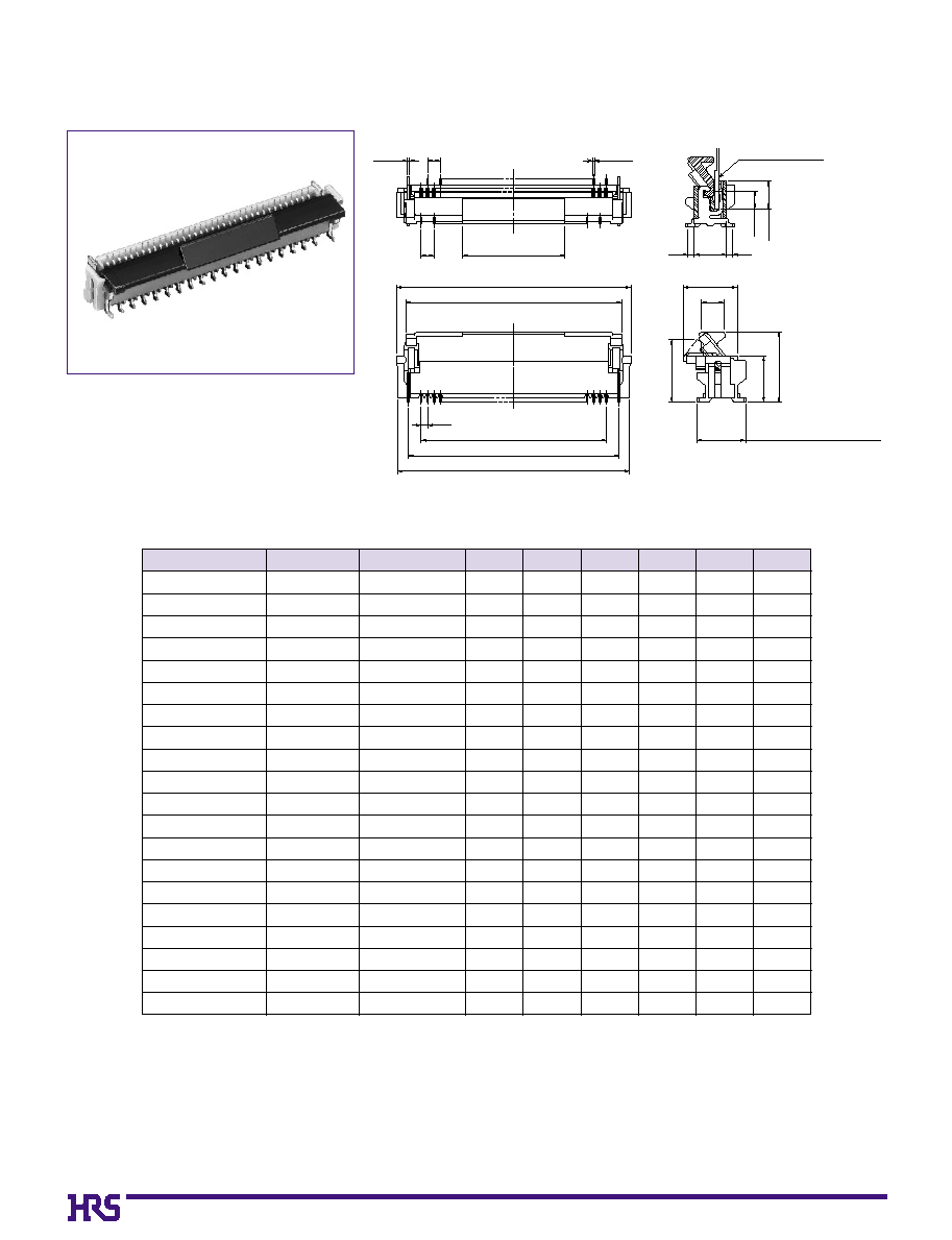
s
0.5mm Pitch Vertical mounting Type
( 0.15 )
1
0.2
1
F
A
B
C
D
E
3.8(Metal
fitting dimension)
3.6
5.5
1.75
4.25
(4.85
)
0.5
1.4
2.15
0.52.50.5
Mated Cross-sectional Diagram
FPC/FFC Contact Surface
(
(
)
)
(
)
(
)
(
)
D
E
Unit:mm
CL No.
Part Number
586-0560-2
586-0615-2
586-0575-0
586-0561-5
586-0572-1
586-0601-8
586-0573-4
586-0562-8
586-0589-4
586-0563-0
586-0664-8
586-0564-3
586-0699-2
586-0565-6
586-0706-6
586-0641-2
586-0566-9
586-0567-1
586-0602-0
586-0568-4
FH12-10S-0.5SV
FH12-12S-0.5SV
FH12-13S-0.5SV
FH12-15S-0.5SV
FH12-16S-0.5SV
FH12-17S-0.5SV
FH12-18S-0.5SV
FH12-20S-0.5SV
FH12-22S-0.5SV
FH12-24S-0.5SV
FH12-26S-0.5SV
FH12-30S-0.5SV
FH12-32S-0.5SV
FH12-33S-0.5SV
FH12-34S-0.5SV
FH12-36S-0.5SV
FH12-40S-0.5SV
FH12-45S-0.5SV
FH12-49S-0.5SV
FH12-50S-0.5SV
Number of Contacts
10
12
13
15
16
17
18
20
22
24
26
30
32
33
34
36
40
45
49
50
A
B
0
8.4
0
9.4
0
9.9
10.9
11.4
11.9
12.4
13.4
14.4
15.4
16.4
18.4
19.4
19.9
20.4
21.4
23.4
25.9
27.9
28.4
0
6.9
0
7.9
0
8.4
0
9.4
0
9.9
10.4
10.9
11.9
12.9
13.9
14.9
16.9
17.9
18.4
18.9
19.9
21.9
24.4
26.4
26.9
C
0
4.5
0
5.5
0
6.0
0
7.0
0
7.5
0
8.0
0
8.5
0
9.5
10.5
11.5
12.5
14.5
15.5
16.0
16.5
17.5
19.5
22.0
24.0
24.5
0
6.5
0
7.5
0
8.0
0
9.0
0
9.5
10.0
10.5
11.5
12.5
13.5
14.5
16.5
17.5
18.0
18.5
19.5
21.5
24.0
26.0
26.5
0
8.2
0
9.2
0
9.7
10.7
11.2
11.7
12.2
13.2
14.2
15.2
16.2
18.2
19.2
19.7
20.2
21.2
23.2
25.7
27.7
28.2
F
4
4
4
4
4
4
4
4
8
8
8
8
8
8
8
8
8
8
8
8
Note 1 : Embossed tape reel packaging (1,000 pieces/reel).
Order by number of reels.
17
6
10
11
12
13
14
15
16
17
18
19
20
22
24
0
2.5
0
4.5
0
5.0
0
5.5
0
6.0
0
6.5
0
7.0
0
7.5
0
8.0
0
8.5
0
9.0
0
9.5
10.5
11.5
0
3.5
0
5.5
0
6.0
0
6.5
0
7.0
0
7.5
0
8.0
0
8.5
0
9.0
0
9.5
10.0
10.5
11.5
12.5
25
26
28
29
30
32
33
34
36
40
42
45
50
53
12.0
12.5
13.5
14.0
14.5
15.5
16.0
16.5
17.5
19.5
20.5
22.0
24.5
26.0
13.0
13.5
14.5
15.0
15.5
16.5
17.0
17.5
18.5
20.5
21.5
23.0
25.5
27.0
6
10
11
12
13
14
15
16
17
18
19
20
22
24
0
2.5
0
4.5
0
5.0
0
5.5
0
6.0
0
6.5
0
7.0
0
7.5
0
8.0
0
8.5
0
9.0
0
9.5
10.5
11.5
0
8.1
10.1
10.6
11.1
11.6
12.1
12.6
13.1
13.6
14.1
14.6
15.1
16.1
17.1
0
4.5
0
6.5
0
7.0
0
7.5
0
8.0
0
8.5
0
9.0
0
9.5
10.0
10.5
11.0
11.5
12.5
13.5
25
26
28
29
30
32
33
34
36
40
42
45
50
53
12.0
12.5
13.5
14.0
14.5
15.5
16.0
16.5
17.5
19.5
20.5
22.0
24.5
26.0
17.6
18.1
19.1
19.6
20.1
21.1
21.6
22.1
23.1
25.1
26.1
27.6
30.1
31.6
14.0
14.5
15.5
16.0
16.5
17.5
18.0
18.5
19.5
21.5
22.5
24.0
26.5
28.0
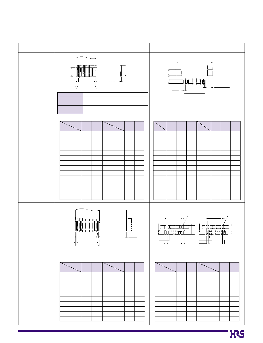
B
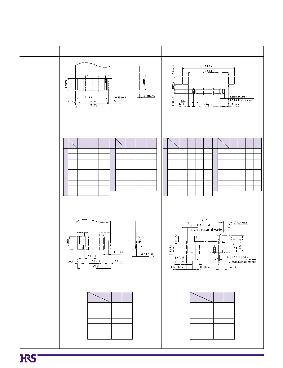
Recommended FPC/FFC dimensions and Land/Metal Mask dimensions
q
0.5mm Pitch Product
Dimension
Number
of Contacts
A
B
A
B
Dimension
Number
of Contacts
Unit: mm
Dimension
Number
of Contacts
A
B
C
Dimension
Number
of Contacts
A
B
C
Unit: mm
Land / Metal Mask dimensions
FPC/FFC dimensions
0.5mm Pitch
Bottom Contact
Type
0.5mm Pitch
Top Contact
Type
C
0.5±0.1
0.5±0.05
A±0.05
B±0.07
0.35±0.03(FPC)
0.3±0.03(FFC)
3.5MIN
4.5MIN
B±0.1
C±0.1
A±0.05
0.5±0.05
0.3±0.03(Land)
0.25±0.03(Metal mask)
2.2
±
0.1
1.5
±
0.1
1.3
±
0.1
Recommended metal mask thickness : 0.15mm
0.5mm Pitch
Vertical
Mounting Type
*
Set the stiffener thickness to 0.188 (7.5mil) min.
0.8±0.1(Land)
0.65±0.05(Metal mask)
0.6±0.1(Land)
0.5±0.05(Metal mask)
0.5±0.1
0.5±0.05
0.3±0.05
A±0.05
B±0.07
0.35±0.03(FPC)
Recommended metal mask thickness : 0.15mm
Even contact number
Odd contact number
0.3±0.03(FFC)
2MIN
3MIN
0.5±0.05
1±0.05
1±0.05
1±0.05
A±0.1
B±0.05
1.8
±
0.1
1.8
±
0.1
0.8±0.1(Land)
0.65±0.05(Metal mask)
0.6±0.1(Land)
0.5±0.05(Metal mask)
0.5±0.05
1±0.05
1±0.05
1±0.05
A±0.1
No.1 contact
No.1 contact
B±0.05
1.8
±
0.1
1.8
±
0.1
1.5
±
0.1
1.5
±
0.1
4.5
±
0.1
1.5
±
0.1
1.5
±
0.1
4.5
±
0.1
10
12
13
15
16
17
18
20
22
24
0
4.5
0
5.5
0
6.0
0
7.0
0
7.5
0
8.0
0
8.5
0
9.5
10.5
11.5
0
5.5
0
6.5
0
7.0
0
8.0
0
8.5
0
9.0
0
9.5
10.5
11.5
12.5
26
30
32
33
34
36
40
45
49
50
12.5
14.5
15.5
16.0
16.5
17.5
19.5
22.0
24.0
24.5
13.5
15.5
16.5
17.0
17.5
18.5
20.5
23.0
25.0
25.5
Dimension
Number
of Contacts
A
B
A
B
Dimension
Number
of Contacts
Unit: mm
10
12
13
15
16
17
18
20
22
24
0
6.5
0
7.5
0
8.0
0
9.0
0
9.5
10.0
10.5
11.5
12.5
13.5
0
4.5
0
5.5
0
6.0
0
7.0
0
7.5
0
8.0
0
8.5
0
9.5
10.5
11.5
26
30
32
33
34
36
40
45
49
50
14.5
16.5
17.5
18.0
18.5
19.5
21.5
24.0
26.0
26.5
12.5
14.5
15.5
16.0
16.5
17.5
19.5
22.0
24.0
24.5
Dimension
Number
of Contacts
A
B
A
B
Dimension
Number
of Contacts
Unit: mm
Product Type
Types other than
those below
Types with an FPC end
thickness of 0.18 mm
C Dimension
0.3
±0.05min
Stiffener thickness should be 0.188 mm (7.5 mil)
min
0.18
±0.05
18
Note 1: Embossed tape reel packaging (2,000 pieces/reel).
Order by number of reels.
Note 2: The 1mm version of FH12 is constructed by loading every other contact into the 0.5mm housing.
When a housing designed for an odd number of 0.5mm pitch contacts is used; the spacing from the
edge to the first contact on either side is the same as the distance between each contact, 1.0mm.
Hirose considers this design to be a standard-type 1.0mm connector.
Note 2:
An eccentric-type connector using a housing designed for an even number of 0.5mm pitch contacts
and consequently one side has 1.5mm distance from the edge to the first contact. (See FPC/FFC
dimensional drawing on page 19) The part number for the eccentric type describes the size of the
0.5mm housing used and lists the number of 1.0mm pitch contacts in parentheses () as shown in the
above table.
D
E
Unit:mm
CL No.
Part Number
586-0591-6
586-0607-4
586-0535-5
586-0579-0
586-0540-5
586-0668-9
586-0536-8
586-0547-4
586-0592-9
586-0537-0
586-0538-3
586-0539-6
586-0541-8
586-0542-0
586-0543-3
586-0546-1
586-0548-7
FH12-
0
5S-1SH
FH12-
0
6S-1SH
FH12-
0
7S-1SH
FH12-
0
8S-1SH
FH12-
0
9S-1SH
FH12-11S-1SH
FH12-16S-1SH
FH12-22S-1SH
FH12-26S-1SH
FH12-10(4)SA-1SH
FH12-14(6)SA-1SH
FH12-18(8)SA-1SH
FH12-22(10)SA-1SH
FH12-24(11)SA-1SH
FH12-30(14)SA-1SH
FH12-40(19)SA-1SH
FH12-50(24)SA-1SH
Number of Contacts
5
6
7
8
9
11
16
22
26
4
6
8
10
11
14
19
24
A
B
0
4
0
5
0
6
0
7
0
8
10
15
21
25
0
3
0
5
0
7
0
9
10
13
18
23
0
8.6
0
9.6
10.6
11.6
12.6
14.6
19.6
25.6
29.6
0
8.1
10.1
12.1
14.1
15.1
18.1
23.1
28.1
C
0
9.6
10.6
11.6
12.6
13.6
15.6
20.6
26.6
30.6
0
9.1
11.1
13.1
15.1
16.1
19.1
24.1
29.1
0
6.07
0
7.07
0
8.07
0
9.07
10.07
12.07
17.07
23.07
27.07
0
5.57
0
7.57
0
9.57
11.57
12.57
15.57
20.57
25.57
2.3
2.3
2.3
2.3
2.3
2.3
2.3
2.3
2.3
2.8
2.8
2.8
2.8
2.8
2.8
2.8
2.8
Standard
type
Eccentric
t
ype
s
1mm Pitch Type Bottom Contact Type
(0.2)
(2.1)
(3.1)
(4.8)
(1.3)
2.3
E
FPC/FFC Contact Surface
D
1.0
A
0.8
2
1.2
B
C
1.85
2
5.6
4.6
Mated Cross-sectional Diagram
19
Note: Embossed tape reel packaging (1,000 pieces/reel).
Order by number of reels.
D
E
F
Unit:mm
CL No.
Part Number
586-0605-9
586-0610-9
586-0593-1
586-0574-7
586-0634-7
586-0584-0
586-0594-4
FH12-
0
6S-1SV
FH12-
0
7S-1SV
FH12-
0
8S-1SV
FH12-16S-1SV
FH12-20S-1SV
FH12-22S-1SV
FH12-24S-1SV
Number of Contacts
6
7
8
16
20
22
24
A
B
0
9.9
10.9
11.9
19.9
23.9
25.9
27.9
0
8.4
0
9.4
10.4
18.4
22.4
24.4
26.4
C
0
5
0
6
0
7
15
19
21
23
0
8
0
9
10
18
22
24
26
0
9.7
10.7
11.7
19.7
23.7
25.7
27.7
4
4
4
8
8
8
8
s
1mm Pitch Vertical Mounting Type
(0.15)
(0.2)
2
2
F
A
B
C
D
E
3.8(
Metal fitting dimension)
3.6
5.5
(4.85)
(2.15)
(1.4)
(4.25)
(1.75)
1.0
0.52.50.5
Mated Cross-sectional Diagram
FPC/FFC Contact Surface
20
B
Recommended FPC/FFC dimensions and Land/Metal Mask dimensions
q
1mm Pitch Product
Land / Metal Mask dimensions
FPC/FFC dimensions
1mm Pitch
Bottom Contact
Type
1mm Pitch
Vertical
Mounting Type
Set the stiffener thickness to 0.188 (7.5mil) min.
Recommended metal mask thickness : : 0.15mm
5
6
7
8
9
11
16
22
26
0
4
0
5
0
6
0
7
0
8
10
15
21
25
0
6
0
7
0
8
0
9
10
12
17
23
27
1
1
1
1
1
1
1
1
1
4
6
8
10
11
14
19
24
0
3
0
5
0
7
0
9
10
13
18
23
0
5.5
0
7.5
0
9.5
11.5
12.5
15.5
20.5
25.5
1.5
1.5
1.5
1.5
1.5
1.5
1.5
1.5
Dimension
Number
of Contacts
A
B
C
Dimension
Number
of Contacts
A
B
C
Unit: mm
6
7
8
16
20
22
24
0
5
0
6
0
7
15
19
21
23
0
7
0
8
0
9
17
21
23
25
Dimension
Number
of Contacts
A
B
Unit: mm
6
7
8
16
20
22
24
0
8
0
9
10
18
22
24
26
0
5
0
6
0
7
15
19
21
23
Dimension
Number
of Contacts
A
B
Unit: mm
*
Set the stiffener thickness to 0.188 (7.5mil) min.
5
6
7
8
9
11
16
22
26
0
4
0
5
0
6
0
7
0
8
10
15
21
25
10.6
11.6
12.6
13.6
14.6
16.6
21.6
27.6
31.6
0
7
0
8
0
9
10
11
13
18
24
28
4
6
8
10
11
14
19
24
0
3
0
5
0
7
0
9
10
13
18
23
10.1
12.1
14.1
16.1
17.1
20.1
25.1
30.1
0
6.5
0
8.5
10.5
12.5
13.5
16.5
21.5
26.5
Dimension
Number
of Contacts
A
B
C
Dimension
Number
of Contacts
A
B
C
1.5
1.5
1.5
1.5
1.5
1.5
1.5
1.5
1.5
2
2
2
2
2
2
2
2
D
D
Unit: mm
Standard
T
ype
Eccentric
T
ype
Eccentric
T
ype
Standard
T
ype
Recommended metal mask thickness : 0.15mm
21
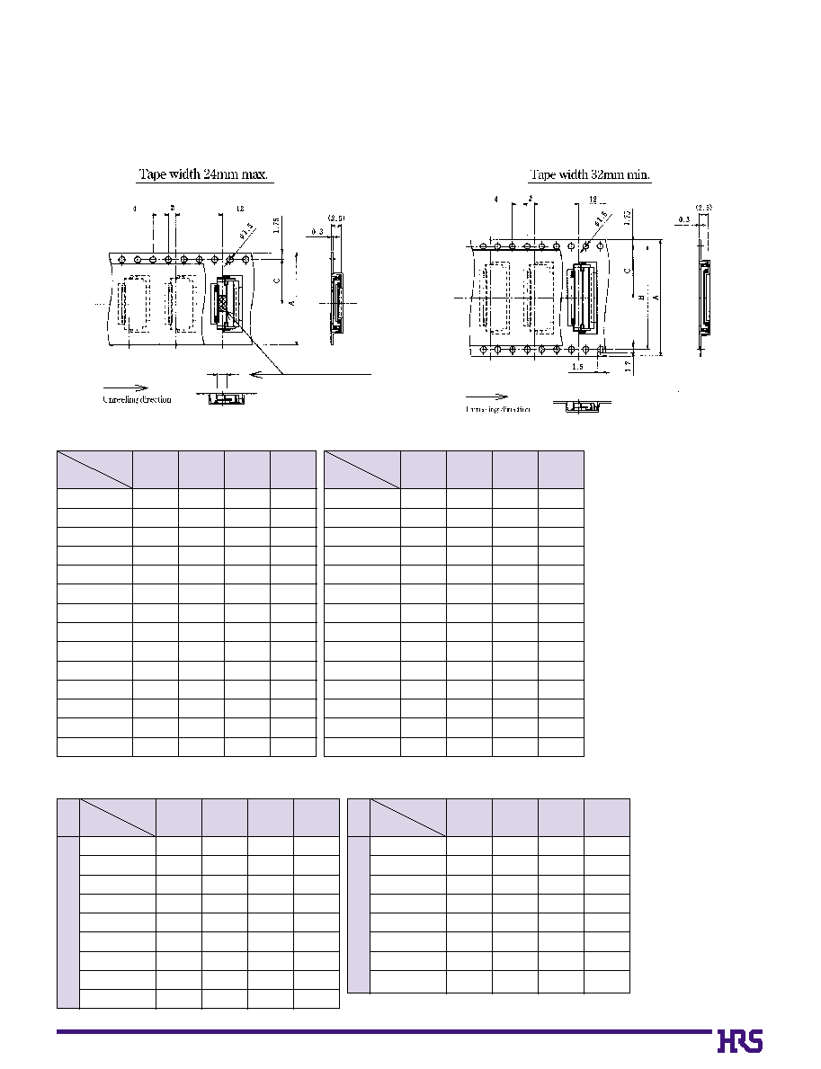
Note: 2,000 pieces per reel.
Unit:mm
B
Packaging Specification
Embossed Carrier Tape Dimensions
Horizontal Type (Common to Bottom/Top Contact, 0.5mm/1mm Pitch)
A
Dimension
Number
of Contacts
16
16
16
24
24
24
24
24
24
24
24
24
24
24
6
10
11
12
13
14
15
16
17
18
19
20
22
24
B
----------
----------
----------
----------
----------
----------
----------
----------
----------
----------
----------
----------
----------
----------
C
0
7.5
0
7.5
0
7.5
11.5
11.5
11.5
11.5
11.5
11.5
11.5
11.5
11.5
11.5
11.5
D
16.5
16.5
16.5
24.5
24.5
24.5
24.5
24.5
24.5
24.5
24.5
24.5
24.5
24.5
A
Dimension
Number
of Contacts
24
24
32
32
32
32
32
32
44
44
44
44
44
44
25
26
28
29
30
32
33
34
36
40
42
45
50
53
B
----------
----------
28.4
28.4
28.4
28.4
28.4
28.4
40.4
40.4
40.4
40.4
40.4
40.4
C
11.5
11.5
14.2
14.2
14.2
14.2
14.2
14.2
20.2
20.2
20.2
20.2
20.2
20.2
D
24.5
24.5
32.5
32.5
32.5
32.5
32.5
32.5
44.5
44.5
44.5
44.5
44.5
44.5
Note: 2,000 pieces per reel.
Unit:mm
A
Dimension
Number
of Contacts
16
24
24
24
24
32
44
44
4
6
8
10
11
14
19
24
Eccentric
T
ype
B
----------
----------
----------
----------
----------
28.4
40.4
40.4
C
0
7.5
11.5
11.5
11.5
11.5
14.2
20.2
20.2
D
16.5
24.5
24.5
24.5
24.5
32.5
44.5
44.5
q
1mm Pitch Bottom Contact Type
q
0.5mm Pitch Bottom/Top Contact Type
Standard
T
ype
A
Dimension
Number
of Contacts
16
24
24
24
24
24
32
44
44
5
6
7
8
9
11
16
22
26
B
----------
----------
----------
----------
----------
----------
28.4
40.4
40.4
C
0
7.5
11.5
11.5
11.5
11.5
11.5
14.2
20.2
20.2
D
16.5
24.5
24.5
24.5
24.5
24.5
32.5
44.5
44.5
(2.0)
Flat surface for placement
with Automatic equipment
22
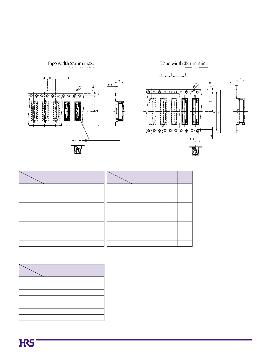
Note: 1,000 pieces per reel.
Note: 1,000 pieces per reel.
Unit:mm
Vertical Mounting Type (Common to 0.5mm/1mm Pitch)
A
Dimension
Number
of Contacts
16
16
24
24
24
24
24
24
24
24
10
12
13
15
16
17
18
20
22
24
B
----------
----------
----------
----------
----------
----------
----------
----------
----------
----------
C
0
7.5
0
7.5
11.5
11.5
11.5
11.5
11.5
11.5
11.5
11.5
D
16.5
16.5
24.5
24.5
24.5
24.5
24.5
24.5
24.5
24.5
A
Dimension
Number
of Contacts
24
24
24
32
44
44
44
6
7
8
16
20
22
24
B
----------
----------
----------
28.4
40.4
40.4
40.4
C
11.5
11.5
11.5
14.2
20.2
20.2
20.2
D
24.5
24.5
24.5
32.5
44.5
44.5
44.5
A
Dimension
Number
of Contacts
24
32
32
32
44
44
44
44
44
44
26
30
32
33
34
36
40
45
49
50
B
----------
28.4
28.4
28.4
40.4
40.4
40.4
40.4
40.4
40.4
C
11.5
14.2
14.2
14.2
20.2
20.2
20.2
20.2
20.2
20.2
D
24.5
32.5
32.5
32.5
44.5
44.5
44.5
44.5
44.5
44.5
q
1mm Pitch Vertical mounting Type
q
0.5mm Pitch Vertical mounting Type
Unit:mm
(1.75)
Flat surface for placement
with Automatic equipment
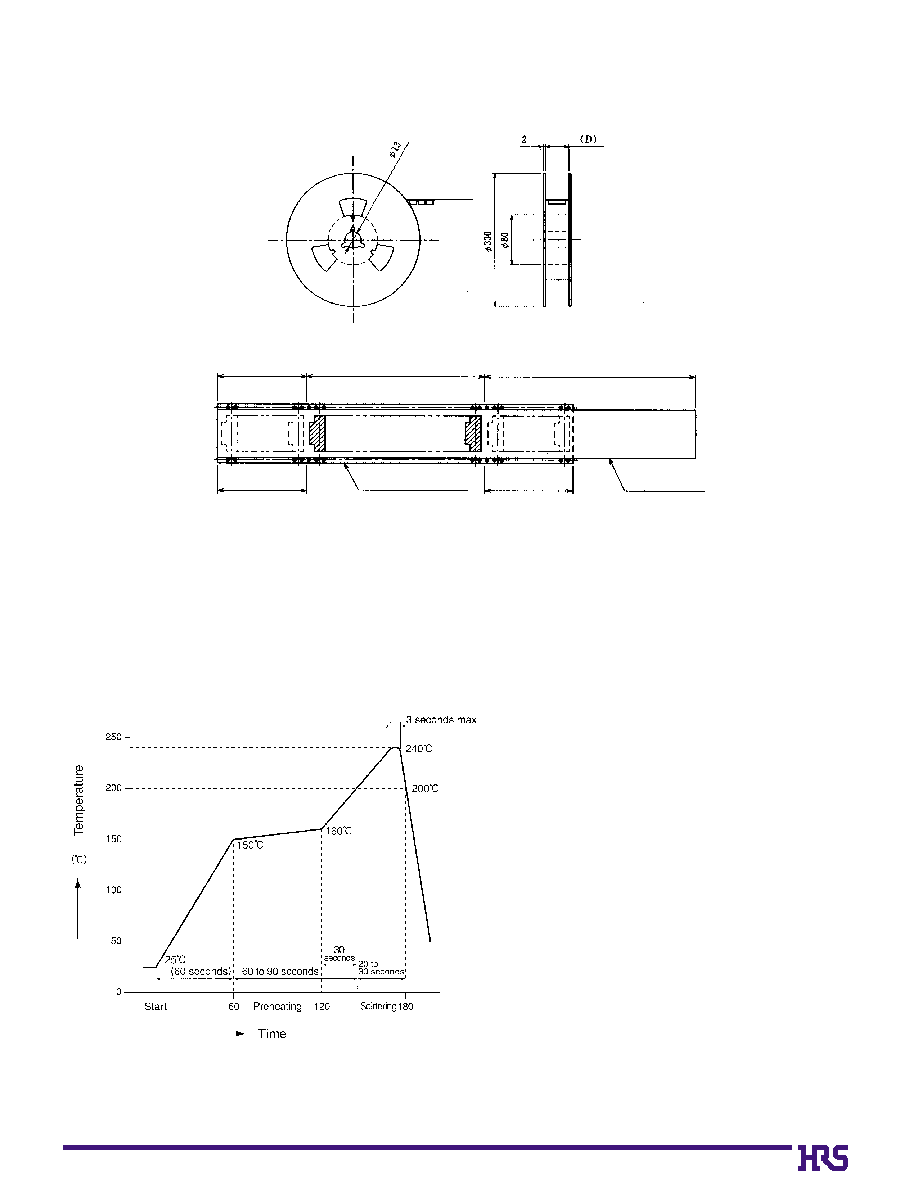
HRS test conditions
Solder method
:Reflow, IR/hot air
(Nihon Den-netsu Co., Ltd.'s
Part Number: SENSBY NR-2)
Environment:
:Room air
Solder composition
:Paste, 63%Sn/37%Pb
(Senju Metal Industry, Co., Ltd.'s
Part Number: OZ63-201C-50-9)
Test board
:Glass epoxy 40mm80mm1.6mm thick
Land dimensions
:Top and bottom
contact type 0.3mm1.3mm
Vertical mounting type 0.6mm1.5mm
Metal mask
:Top and bottom contact type
0.25mm1.3mm0.15mm thick
Vertical mounting type
0.25mm1.5mm0.15mm thick
This temperature profile is based on the above conditions.
In individual applications the actual temperature may vary,
depending on solder paste type, volume/thickness and board
size/thickness. Consult your solder paste and equipment
manufacturer for specific recommendations.
23
Reel Dimensions (Common to All Types)
B
Recommended Temperature Profile
End portion
Mounting portion
Lead portion (400mm min.)
Top cover tape
Blank portion
(10 pockets min.)
Embossed carrier tape
Blank portion
(10 pockets min.)
24
25
25
5
35
25
25
30
175
295
B
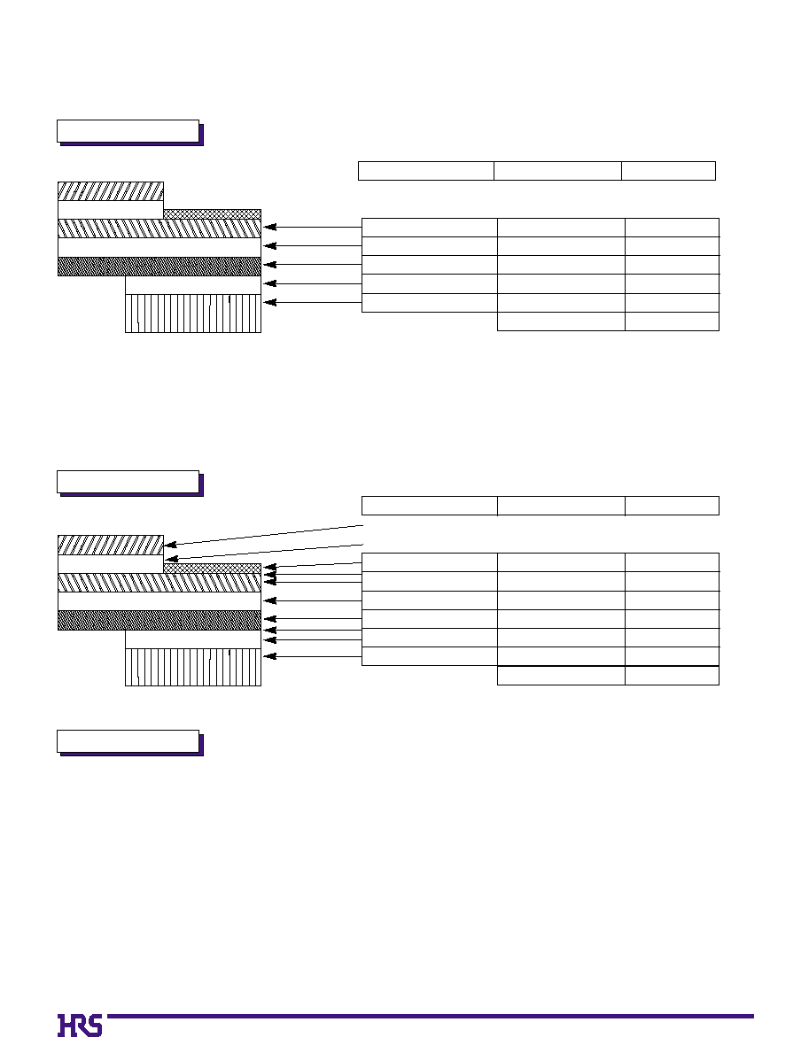
FH12 Series FPC/FFC Construction (Recommended Specifications)
1. FFC
FFC : Flexible Flat Cable
FPC : Flexible Printed Circuit
Material Name
Material
Thickness (
µ
m)
2. FPC
3. Precautions
Material Name
Covering layer film
Cover adhesive
Surface treatment
Copper foil
Base adhesive
Base film
Reinforcement material adhesive
Stiffener
Material
Thickness (
µ
m)
1. This specification is a recommendation for the construction of the FH12 Series FPC and FFC (t=0.3
±
0.05).
2. For details about the construction, please contact the FPC/FFC manufacturers.
Note: Use of a thicker FFC results in a stiffer lock action and the lock is more easily released.
A factor that contributes to thicker FFC is the use of 250
µ
m stiffener which is thicker than the standard (188
µ
m) product. This
results in a total thickness of 357
µ
m.
When using FFC, control of FFC thickness becomes easy if you indicate to us the thickness of the stiffener.
*
Real tolerance of thickness dimension is on the order of
±
20
µ
m (275 to 315
µ
m)
35
30
12
30
188
295
Hard copper foil with tin plating
Adhesive
Polyester
Adhesive
Stiffener
(Note)
Polyester type
Polyester type
Polyester type
Total
Polyamide 1 mil
Tin-lead
Cu
1oz
Polyamide 1 mil
Heat-hardened adhesive
Polyamide 7 mil
Total