Äîêóìåíòàöèÿ è îïèñàíèÿ www.docs.chipfind.ru
66
High Density FPC Connector (0.3mm/0.4mm/0.5mm Pitch)
FH16 Series
s
Features
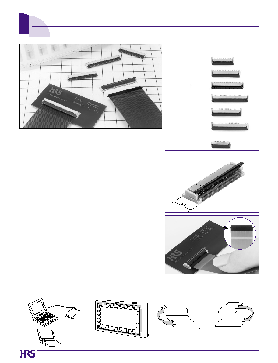
1. High Density FPC Connector
The FH16 series is a fine pitch, zero insertion force (ZIF), right angle, bottom
contact, connector compatible with flexible printed circuits (FPC) with a pitch
of 0.3mm, 0.4mm, and 0.5mm and a recommended thickness of 0.295mm for
single-sided or 0.306mm for double-sided. The FH16 provides a higher pin
count given the same amount of board space than other manufacturers of
similar product. With a large selection in pin density, the FH16 series greatly
improves design flexibility.
FH16
: 0.3mm pitch 60, 80, and 90 contacts
FH16M : 0.4mm pitch 80 and 96 contacts
FH16H : 0.5mm pitch 50 contacts
FH16P : 0.5mm pitch 64 contacts
2. Easy mounting on PCB
FH16 supports 0.3mm pitch cable but only requires a 0.6mm pitch pad
layout on the PCB. The FH16's staggered pin design allows the
mounting lead area to be twice as wide as the FPC contact area making
it easier to place the connector on the board given the fine pitch of the
contacts.
3. User Friendly Flip-Lock Design
The flip-lock (one-touch rotating type) ZIF structure secures the FPC
connection with a single and light force. This design helps simplify
assembly and repair work. When locking the FPC, the audible click
assures the assembly worker of a steady FPC connection resulting in
improved customer service.
4. Prevents FPC from escape and oblique mating
The FH16 series with its recommended FPC dimensions prevents the
FPC from escape and oblique mating thereby securing a steady
connection.
5. Compatible with Automatic Assembly Tooling
Embossed tape packaging allows for automatic placement onto the PCB.
Mechanism to prevent
FPC from escape and oblique
mating
Excellent Serviceability with Flip-Lock Design
s
Applications
Notebook computers, printers, PDAs, digital cameras and other compact devices for interconnecting the main circuit board with the
LCD,PDP(Plasma Display),HDD or other device.
0.3mm pitch 60 contact
FH16 Series Variation
0.3mm pitch 80 contact
0.3mm pitch 90 contact
0.4mm pitch 80 contact
0.5mm pitch 50 contact
0.5mm pitch 64 contact
0.5mm pitch 30 contact
[Conventional product (FH12 series)]
Hard
Disk-Drive
PCB
PCB
PCB
Flip-lock type
Notebook PC
PDP
HDD
67
s
Product Specifications
Applicable cable t=0.30
±
0.05, Tin-lead plating (Note 3)
Part
Insulator
Contact
Material
Polyamide
LCP
PPS
Phosphor bronze
Color : Beige
Color : Dark brown
Tin-lead plating
Gold plating
UL94V-0
Finish
Remarks
s
Ordering Information
FH 16 64S 0.5 SHW (05)
s
Materials
Note 1: Includes temperature rise caused by current flow.
Note 2: The term "storage" refers to products stored for long period of time prior to mounting and use. Operating Temperature Range and
Humidity range covers nonconducting condition of installed connectors in storage, shipment or during transportation.
Note 3: When FPC is gold plated, the connector contacts should be also gold plated: Select the (05) specification.
q
w
e
r
t
y
Ratings Current rating
Voltage rating
0.3mm
Pitch
0.4mm 0.5mm
0.15A
3 0V AC
0.3A
50V AC
0.4A
60V AC
Operating Temperature Range:
40
ç to +
70
ç
Operating Relative Humidity: Relative humidity 90
%
max
(not dewed) Note1
Storage Temperature Range:
10
ç to +
50
ç
Storage Relative Humidity: Relative humidity 90
%
max
(not dewed) Note2
1. Insulation Resistance
2. Withstanding Voltage
3. Contact Resistance
4.
Durability
(Insertion/withdrawal)
5. Vibration
6. Shock
8.
Temperature cycle
500M
ohms
min.
No flashover or insulation breakdown.
No deformation of components affecting performance.
100V DC
applied for one minute
1mA
20 cycles
Item
Specification
Conditions
150m
ohms
max.
*
Including FPC conductor resistance.
150m
ohms
max.
No damage, cracks, or parts dislocation.
No electrical discontinuity of 1µs or more
Contact resistance: 150m
ohms
max.
No damage, cracks, or parts dislocation.
Frequency: 10 to 55 Hz, single amplitude of 0.75 mm,
2 hours in each of the 3 directions.
No electrical discontinuity of 1µs or more
Contact resistance: 150m
ohms
max.
No damage, cracks, or parts dislocation.
Acceleration of 490 m/s
2
, 11 ms duration,
sine half-wave waveform, 3 cycles in each of the 3 axis.
96 hours at temperature of 40ç and humidity of 90% to 95%
0.3mm pitch:
0
90V AC
0.4mm pitch: 150V AC
0.5mm pitch: 200V AC
Contact resistance: 150m
ohms
max.
Insulation resistance: 50M
ohms
min.
No damage, cracks, or parts dislocation.
7.
Humidity
(Steady state)
9.
Resistance to
Soldering heat
Contact resistance: 150m
ohms
max.
Insulation resistance: 50M
ohms
min.
No damage, cracks, or parts dislocation.
Temperature: 40
¡
+15
to
35
ç
¡
+85
ç
¡
+15
ç to
35
ç
Time
: 30 minutes
¡
5 minutes max.
¡
30 minutes
¡
5 minutes max.
5 cycles
Reflow: At the recommended temperature profile
Manual soldering: 350±5ç for 3 seconds
q
Series name
: FH
w
Series No.
: 16
e
Number of contacts : 50, 60, 64, 80, 90, and 96 contacts
r
Contact pitch
: 0.3mm, 0.4mm, 0.5mm
t
Terminal Shape
: SHW(SMT horizontal staggered row mount type)
y
Plating Specification : No symbol : Tin-lead plating (05) : gold plating
68
Positioning point
B
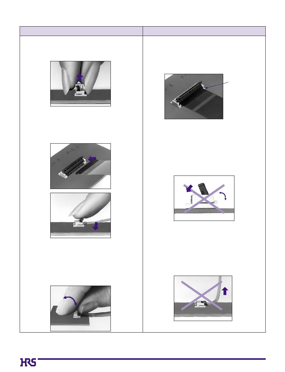
Connector Operating Instructions, precautions and recommendations
2)
The connector will assure reliable performance
when the actuator is open to 120° maximum (see
fig.1) Do not exceed this angle, as this may cause
permanent damage to the connector.
3) Do NOT push/pull actuator. Any damage to actua-
tor will require replacement of the entire connec-
tor.
1) Fully insert the FPC parallel to mounting surface,
with the exposed conductive traces facing down.
120
°
Operation
Precautions
1.FPC Termination procedure. Connector
installed on the board.
1) Remove and dispose the pick-and-place insert.
2) Rotate down the actuator until firmly closed.
It is critical that the inserted FPC is not moved and
remains fully inserted. Should the FPC be moved,
open the actuator and repeat the process, starting
with Step 1 above.
2.FPC Removal
1) Lift up the actuator.
2) Carefully remove the FPC.
Fig.1
69
FH16-60S-0.3SHW
586-0620-2
60
0.3
21.9
17.7
17.4
17.4
18.35
0.3
0.6
FH16-80S-0.3SHW
586-0613-7
80
0.3
27.9
23.7
23.4
23.4
24.35
0.3
0.6
FH16-90S-0.3SHW
586-0697-7
90
0.3
30.9
26.7
26.4
26.4
27.35
0.3
0.6
FH16M-80S-0.4SHW
586-0675-4
80
0.4
36.1
31.6
31.2
31.2
32.25
0.4
0.8
FH16M-96S-0.4SHW
586-0715-7
96
0.4
42.5
38
.0
37.6
37.6
38.65
0.4
0.8
FH16H-50S-0.5SHW
586-0676-7
50
0.5
29.4
24.5
24
.0
24
.0
25.55
0.5
1
.0
FH16P-64S-0.5SHW
586-0649-4
64
0.5
36
.0
31.5
31
.0
31
.0
32.15
0.5
1
.0
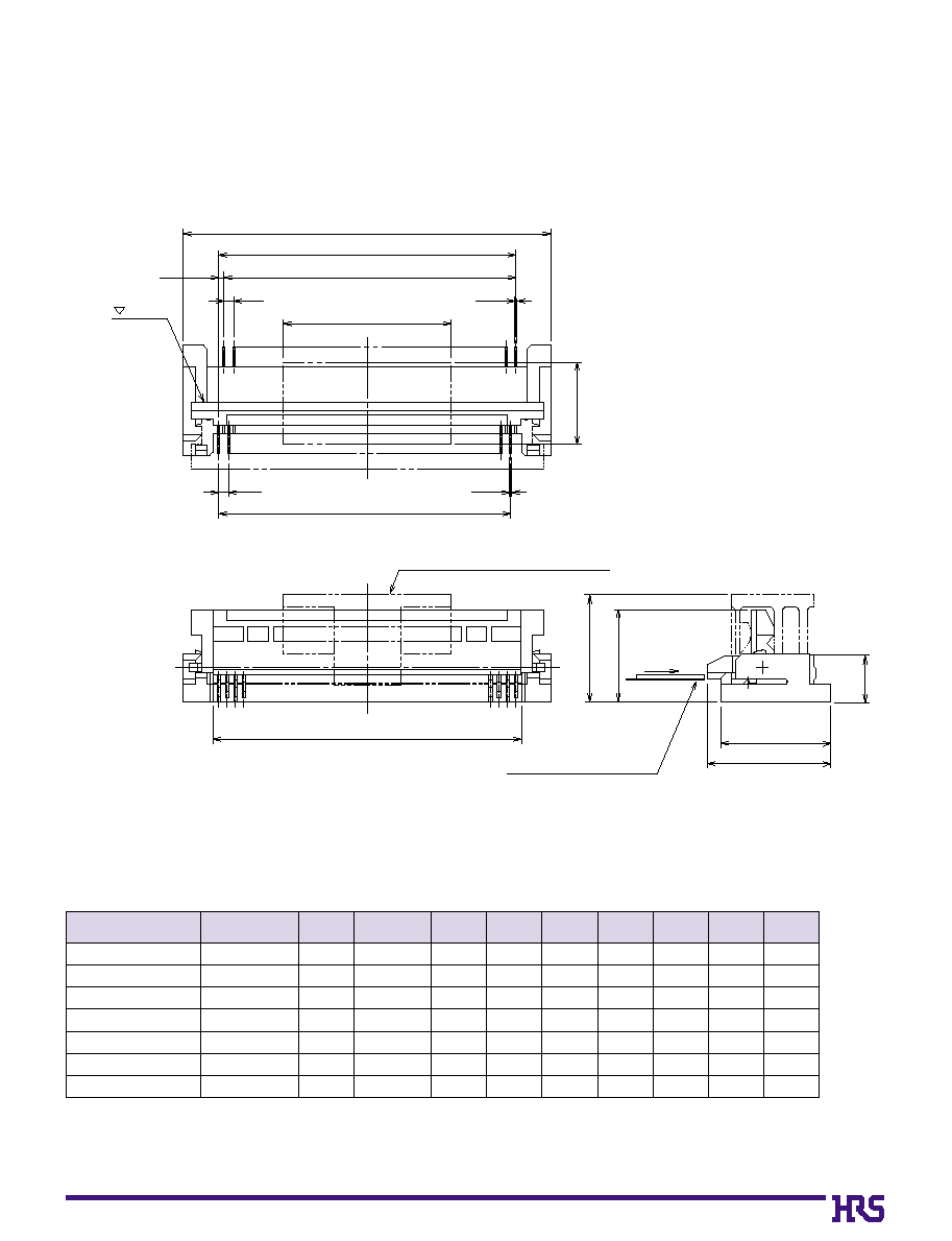
s
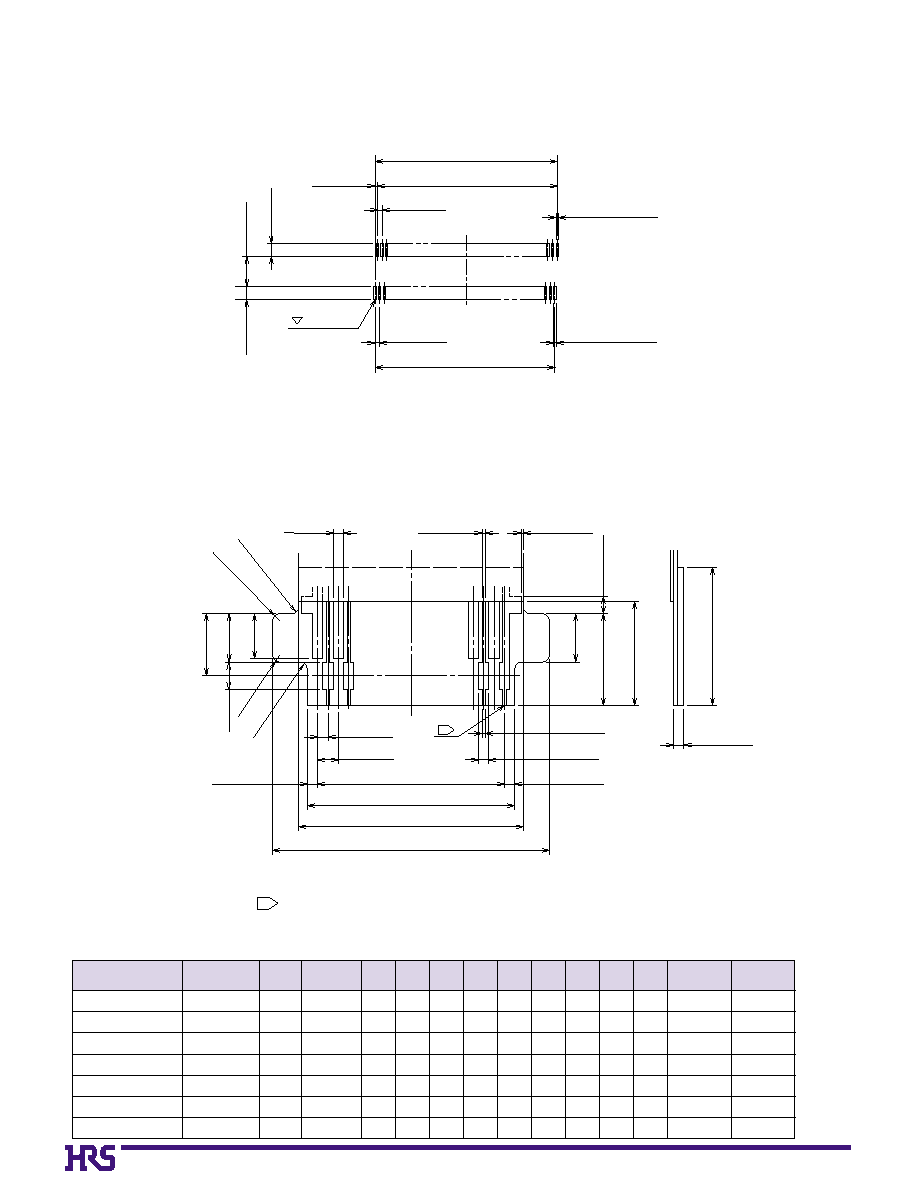
Connector Dimensions
NOTE: Embossed tape reel packaging (1,000 pieces/reel).
Order by number of reels.
Mark
E
6.6
3
FPC Conductive Surface
Suction Parts for Automatic Mounting
5.5
7.4
6.5
10
4.9
A
R
0.12
0.12
R
Q
B
C
D
Unit: mm
Part Number
CL No.
A
B
C
D
E
Q
R
FPC
Contact Pitch
Number of
contacts
70
FH16-60S-0.3SHW
586-0620-2
60
0.3
17.7 17.4 17.4 18.3 18.8 20.3
0.3
0.6
0.3
0.3
±
0.03 0.25
±
0.03
FH16-80S-0.3SHW
586-0613-7
80
0.3
23.7 23.4 23.4 24.3 24.8 26.3
0.3
0.6
0.3
0.3
±
0.03 0.25
±
0.03
FH16-90S-0.3SHW
586-0697-7
90
0.3
26.7 26.4 26.4 27.3 27.8 29.3
0.3
0.6
0.3
0.3
±
0.03 0.25
±
0.03
FH16M-80S-0.4SHW 586-0675-4
80
0.4
31.6 31.2 31.2 32.2 32.7 34.2
0.4
0.8
0.3
0.3
±
0.03 0.25
±
0.03
FH16M-96S-0.4SHW 586-0715-7
96
0.4
38
.0
37.6 37.6 38.6 39.1 40.6
0.4
0.8
0.3
0.3
±
0.03 0.25
±
0.03
FH16H-50S-0.5SHW 586-0676-7
50
0.5
24.5 24
.0
24
.0
25.5 25.5 27.5
0.5
1
.0
0.5
0.6
±
0.1
0 0
0.5
±
0.05
FH16P-64S-0.5SHW 586-0649-4
64
0.5
31.5 31
.0
31
.0
32.1 32.6 34.1
0.5
1
.0
0.3
0.6
±
0.1
0 0
0.5
±
0.05
B
Recommended PCB layout and metal mask dimensions
*
Recommended metal mask thickness: t=0.15
3.95±0.1
1.7±0.1
C±0.05
Q±0.05
R±0.05
W (PCB)
B±0.05
R±0.05
D±0.05
Mark side
X (Metal mask)
X (Metal mask)
W (PCB)
1.7±0.1
B
FPC recommended dimensions
FPC, Land, Metal Mask Dimension Table
1
*
Forced film material shall be polyamide + thermal hardened additives.
Conductor width shall be 0.1±0.05 if FPC has plating bars.
4
MIN
0.3±0.05
R0.2
R0.2
R0.2
Q±0.02
R±0.02
B±0.03
F±0.05
G±0.1
H±0.1
S±0.07
0.1±0.05
0.3
+0.04
_0.03
S±0.07
R0.2
1.4±0.1
2.65±0.2
(
0.5
)
3
MIN
0.07±0.07
0.1±0.05
0.3
+0.04
_0.03
1.4±0.1
1.3±0.1
1.8±0.1
0.8
+0.04 _0.03
2
2
Unit: mm
Part Number
CL No.
Number of
contacts
FPC
Contact Pitch
B
C
D
F
G
H
Q
R
S
W
X
71
FH16-60S-0.3SHW
60
44
40.4
20.2
22.3
44.5
FH16-80S-0.3SHW
80
44
40.4
20.2
28.3
44.5
FH16-90S-0.3SHW
90
44
40.4
20.2
31.3
44.5
FH16M-80S-0.4SHW
80
56
52.4
26.2
36.6
56.5
FH16M-96S-0.4SHW
96
56
52.4
26.2
43
.0
56.5
FH16H-50S-0.5SHW
50
44
40.4
20.2
29.9
44.5
FH16P-64S-0.5SHW
64
56
52.4
26.2
36.6
56.5
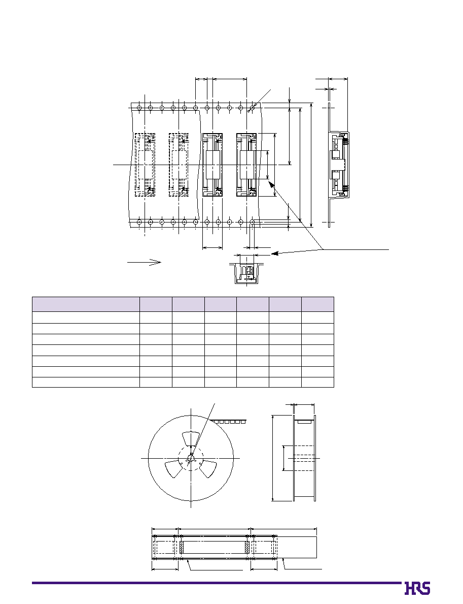
B
Packaging Specification
q
Embossed Carrier Tape Dimensions
M
10
7
12
2
4
Ø1.5
1.75
L
K
J
1.7
1.5
4.9
0.5
6.8
Unreeling direction
q
Reel Dimensions
Unit: mm
NOTE: 1,000 pieces per reel.
T
Ø
80
Ø
370
2
Ø13
End portion
Mounting portion
Lead portion (400mm min.)
Blank portion
Embossed carrier tape
Top cover tape
(10 pocket min.)
Blank portion
(10 pocket min.)
Inserted Connector
J
K
L
M
T
Number of
Contacts
Flat surface for placement
with Automatic equipment
72
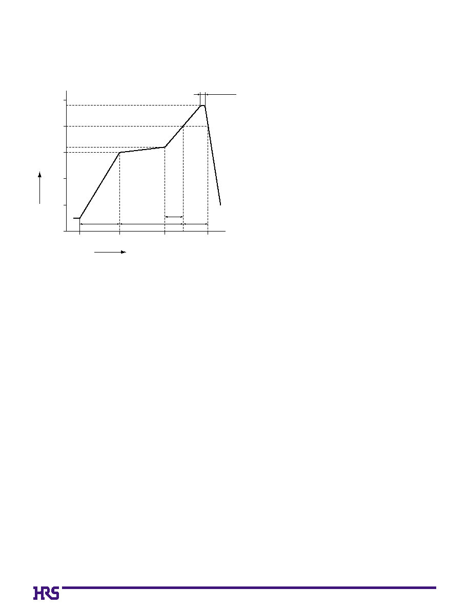
B
Recommended Temperature Profile
HRS test conditions
Solder method
:Reflow, IR/hot air
(Nihon Den-netsu Co., Ltd.'s
Part Number: SENSBY NR-2)
Environment
:Room air
Solder composition
:Paste, 63%Sn/37%Pb
(Senju Metal Industry, Co., Ltd.'s
Part Number: OZ63-201C-50-9)
Test board
:Glass epoxy 45mm80mm1.6mm thick
Land dimensions
:Contact Pitch 0.3mm, 0.4mm
0.3mm1.7mm
Contact Pitch 0.5mm
0.6mm1.7mm
Metal mask
:Contact Pitch 0.3mm, 0.4mm
0.25mm1.7mm0.15mm thick
Contact Pitch 0.5mm
0.5mm1.7mm0.15mm thick
This temperature profile is based on the above conditions.
In individual applications the actual temperature may vary,
depending on solder paste type, volume/thickness and board
size/thickness. Consult your solder paste and equipment
manufacturer for specific recommendations.
5 sec. max.
240ç
200ç
160ç
150ç
25ç
(30 sec.)
60
120
180
(20 to 30 sec.)
Soldering
250
200
150
100
50
0
Start
Time (sec.)
(60 sec.)
60 to 90 sec.
Preheating
Temperature (ç)
73
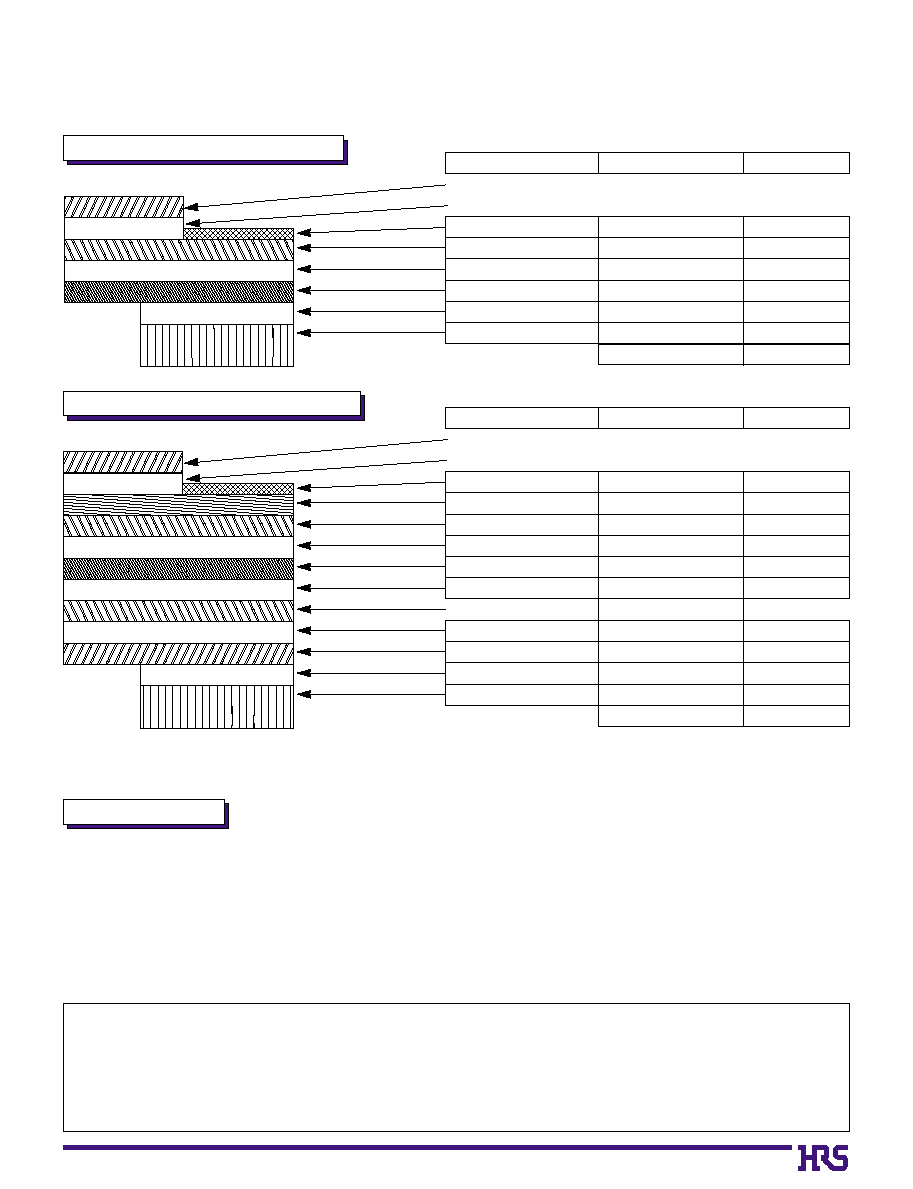
B
FH16 Series FPC Construction (Recommended Specifications)
1. Using Single-Sided FPC
2. Using Double-Sided FPC
3. Precautions
1. This specification is a recommendation for the construction of the FH16 Series FPC (t=0.3
±
0.05).
2. The FH16 Series are connectors for thin FPC which is beginning to be used in cameras and other miniature equipment.
Stiffener is not required for double-sided FPC which will be reflected in FPC cost reduction.
Please note that in the case of single-sided FPC, stiffener is required, but the thickness dimension can be created easily.
For details about the construction, please contact the FPC manufacturer.
Note : To prevent release of the lock due to FPC bending, please do not use copper foil on the rear side.
Material Name
Covering layer film
Cover adhesive
Surface treatment
Copper foil
Base adhesive
Base film
Reinforcement material adhesive
Stiffener
Polyamide 1 mil
Tin-lead plating
Cu
1oz
Polyamide 1 mil
Heat-hardened adhesive
Polyamide 7 mil
Total
25
25
5
35
25
25
30
175
295
Material
Thickness (
µ
m)
Material Name
Covering layer film
Cover adhesive
Surface treatment
Through hole copper
Copper foil
Base adhesive
Base film
Base adhesive
Copper foil
Cover adhesive
Cover layer film
Reinforcement material adhesive
Stiffener
Polyamide 1 mil
Tin-lead plating
Cu
Cu
1/2 oz
Polyamide 1 mil
Cu
1/2 oz
Polyamide 1 mil
Heat-hardened adhesive
Polyamide 1 mil
Total
25
25
5
15
18
18
25
18
18
25
25
50
100
299
Material
Thickness (
µ
m)
Sumitomo Bakelite Co., Ltd. Flexible Printed Circuit Board Division
TEL:+81 3 5462 4191
5-8, Higashi-shinagawa 2-chome, Shinagawa-ku, Tokyo, Japan
FAX:+81 3 5462 4882
Fujikura Ltd. Electronics Global Marketing Department
TEL:+81 3 5606 1165
1-5-1, Kiba, Koto-ku, Tokyo, Japan
FAX:+81 3 5606 1530
NOK Corporation Sales Division Overseas Business Department
TEL:+81 3 3432 6976/8415
1-12-15, Shiba-Daimon, Minato-ku, Tokyo, Japan
FAX:+81 3 3432 3919
FPC Manufactures' Contact List