25
Low Profile 0.5mm Pitch Connectors For FPC
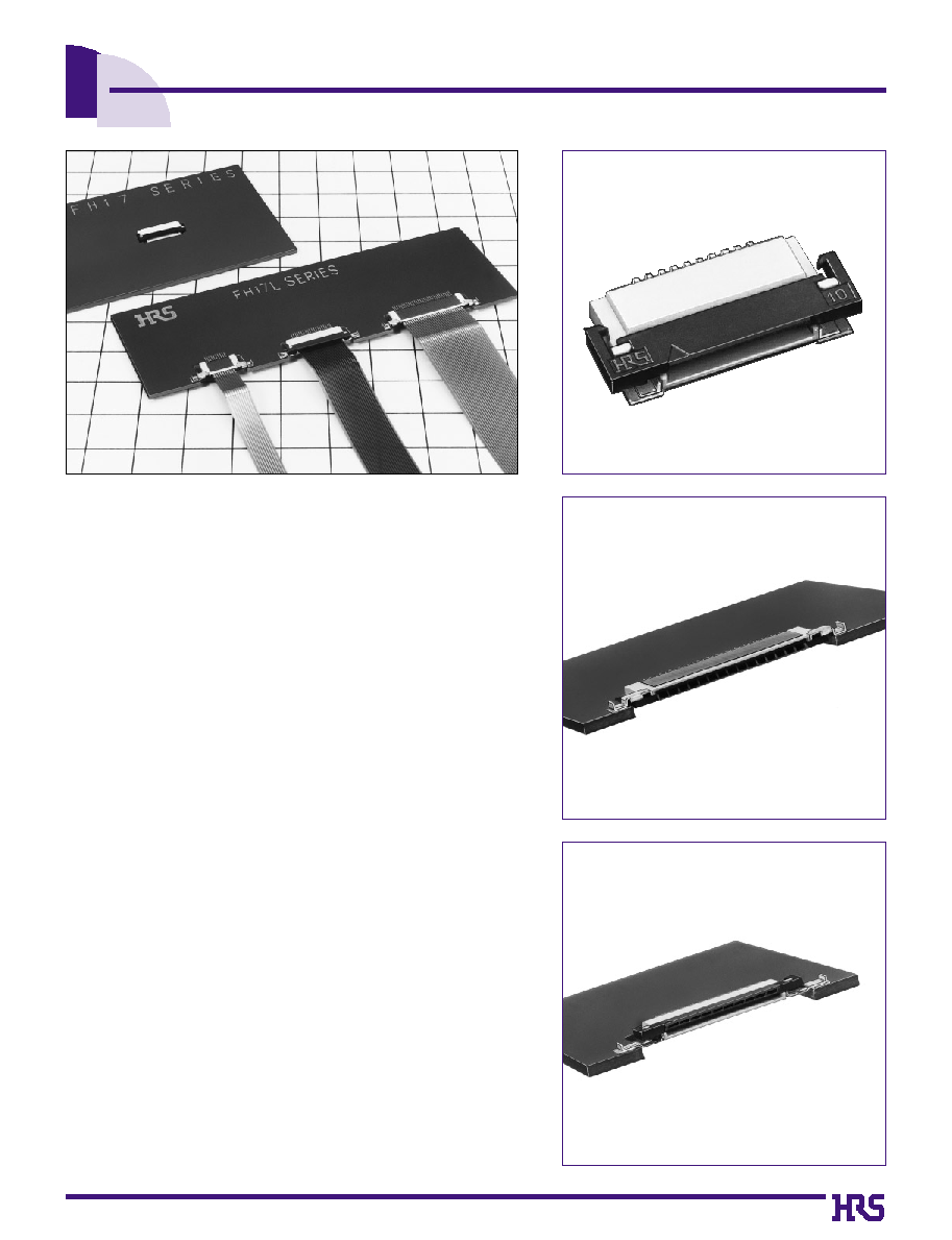
FH17 Series
s
Features
1. Low profile 0.5mm pitch FPC connectors
As products become lighter/thinner/shorter/smaller, requests for
thinly-made type FPC connectors are rapidly increasing. The FH17
Series is an ultra miniature version of the Hirose's popular FH12
Series. FH17 has 35
%-
45
%
lower profile above the board.
*
FH17
: On-board type, height of 1.3 mm from board surface
*
FH17L : Offset standard type, height of 1.0 mm from board surface
*
FH17LR : Offset reverse type, height of 1.0 mm from board surface
2. Easy to use Flip-Lock Actuator
Flip-lock (rotating type) ZIF mechanism enables good connectivity
of FPC by a simple operation and light force. No board space is
required for flip lock operation as compared to slide lock ZIF
connectors.
3. Variety of Sizes and Options
In addition to the on-board type (FH17), board drop-in types (FH17L
and FH17LR) are also available. Selection will depend on the
application mounting. Connectors are available with 8 to 30
contacts.
4. Adaptable to thin-type FPC
It conforms to the thin-type FPC (0.17mm) now being used for small
size electronic equipment such as cameras, etc.
(Thin-type FPC: Specifications without stiffener of double-faced
FPC will reduce the cost of FPC. A single-faced FPC still requires
stiffener, but the reduced thickness is easier for manufacturers to
produce.
5. Packaged for Pick-and-Place machine
Embossed tape packaging allows automatic mounting.
s
Applications
Mobile telephones, devices using LCDs, CD-ROMs, cameras, other
miniature devices
FH17L(board drop-in standard type)flip-lock mechanism
FH17LR (board drop-in reverse type) flip-lock mechanism
FH17 (on-board type) flip-lock mechanism
(

26
s
Product Specifications
100V DC
150V AC/1 minute
20 cycles
1mA
Frequency: 10 to 55 Hz, single amplitude of 0.75 mm,
2 hours in each of the 3 directions.
Acceleration of 490 m/s
2
, 11 ms duration,
sine half-wave waveform, 3 cycles in each of the 3 axis.
96 hours at temperature of 40Á and humidity of 90% to 95%
5 cycles under conditions as follows; Temperature:
-40
Á /
15
to
35
Á /
85
Á /
15
to
35
Á
,
Time: 30
/
5 max.
/
30
/
5 max.(minutes)
Reflow: At the recommended temperature profile
Manual soldering: 350±5Á for 3 seconds
Applicable FPC
t=0.17
Tin-lead plating
+
0.03
-
0.04
Item
1.Insulation resistance
2.
Withstanding voltage
4.
Durability
(Insertion/withdrawal)
3.Contact resistance
5.Vibration
6.Shock
7.
Humidity
(Steady state)
8.Temperature cycle
9.Resistance to
soldering heat
Specification
500M
ohms
minimum
No flashover or insulation breakdown.
50m
ohms
maximum
Contact resistance : 50m
ohms
maximum
No damage, cracks, or parts dislocation.
No electrical discontinuity of 1µs or more
Contact resistance: 50m
ohms
maximum.
No damage, cracks, or parts dislocation.
No electrical discontinuity of 1µs or more
Contact resistance: 50m
ohms
maximum
No damage, cracks, or parts dislocation.
Contact resistance: 50m
ohms
maximum
Insulation resistance: 50M
ohms
minimum
No damage, cracks, or parts dislocation.
Contact resistance: 50m
ohms
maximum
Insulation resistance: 50M
ohms
minimum
No damage, cracks, or parts dislocation.
No deformation of components affecting performance.
Conditions
(Note:4)
FH17L - 30S - 0.5 SH (05)
1
2
3
4
5
6
s
Ordering Information
Remarks
--------------
--------------
UL94V-0
UL94V-0
s
Material
Part
Contact
Metal fittings
Insulated tape
Insulator
Insulator
Material
LCP
PPS
Phosphor bronze
Brass
Polyamide
Finish
--------------
--------------
Tin-lead plating
Tin-lead plating
--------------
2
3
4
5
6
1
Ratings
Current rating
Voltage rating
0.4A DC
50V AC
Operating temp. range
Operatinghumidity range
-
40
to +
70
Á
(Note.1)
relative humidity 90% max.
(No dew-fall)
Storage temp. range
Storage Humidity range
-
10
to +
50
Á
(Note.2)
relative humidity 90% max.
(No dew-fall)
Note 1: Includes temperature rise caused by current flow.
Note 2: The term "storage" refers to products stored for long period of time prior to mounting and use. Operating Temperature Range and
Humidity range covers nonconducting condition of installed connectors in storage, shipment or during transportation.
Note 3. The above standards represent this series. The individual formal agreement should be based on the Specification.
Series Name
FH17
Mounting Type
None : On-Board type
L
: Offset type
LR
: Offset reverse type
Number of Contacts
8, 10, 15, 20, 24, 30
Contacts Pitch
0.5mm
Contact Style
SH : SMT horizontal mounting type
Plating specifications
Blank : Tin-lead plating
(05)
: Gold plating
27
B
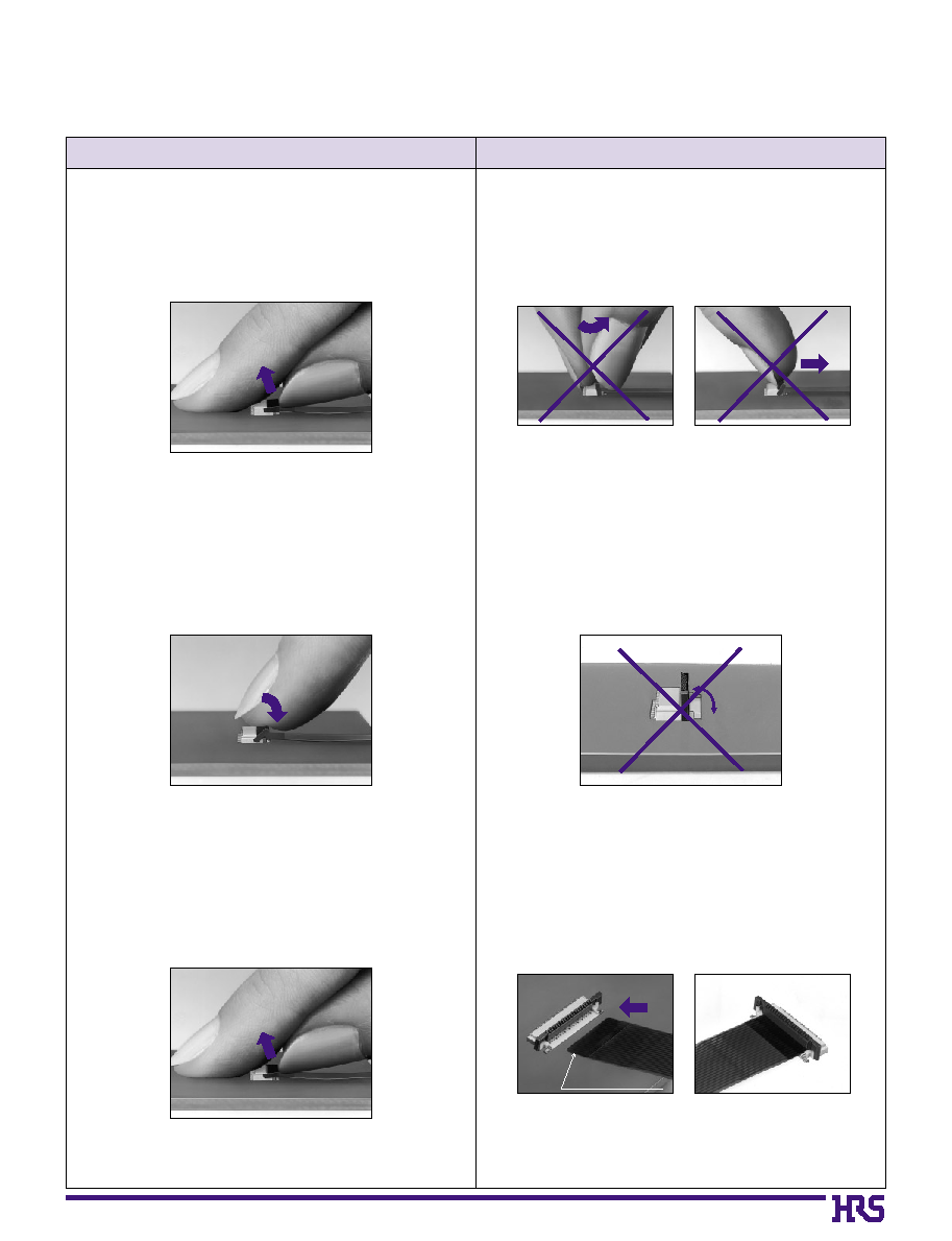
Connector Operating Instructions, precautions and recommendations
Operation
Precautions
1.FPC Termination procedure. Connector
installed on the board.
1) Lift up the actuator. Use thumb or index finger.
2) Rotate down the actuator until firmly closed.
It is critical that the inserted FPC is not moved and
remains fully inserted. Should the FPC be moved,
open the actuator and repeat the process, starting
with Step 1 above.
2)
The connector will assure reliable performance
when the actuator is open to 90∞ maximum (see
fig.1) Do not exceed this angle, as this may cause
permanent damage to the connector.
2.FPC Removal
1) Lift up the actuator.
2) Carefully remove the FPC.
3) Assure that the FPC is fully inserted parallel to
mounting surface, with the exposed conductive
traces facing down.
FPC conductor surface
(Bottom side)
1) Do not apply excessive force or use any type of
tool to operate the actuator.
28
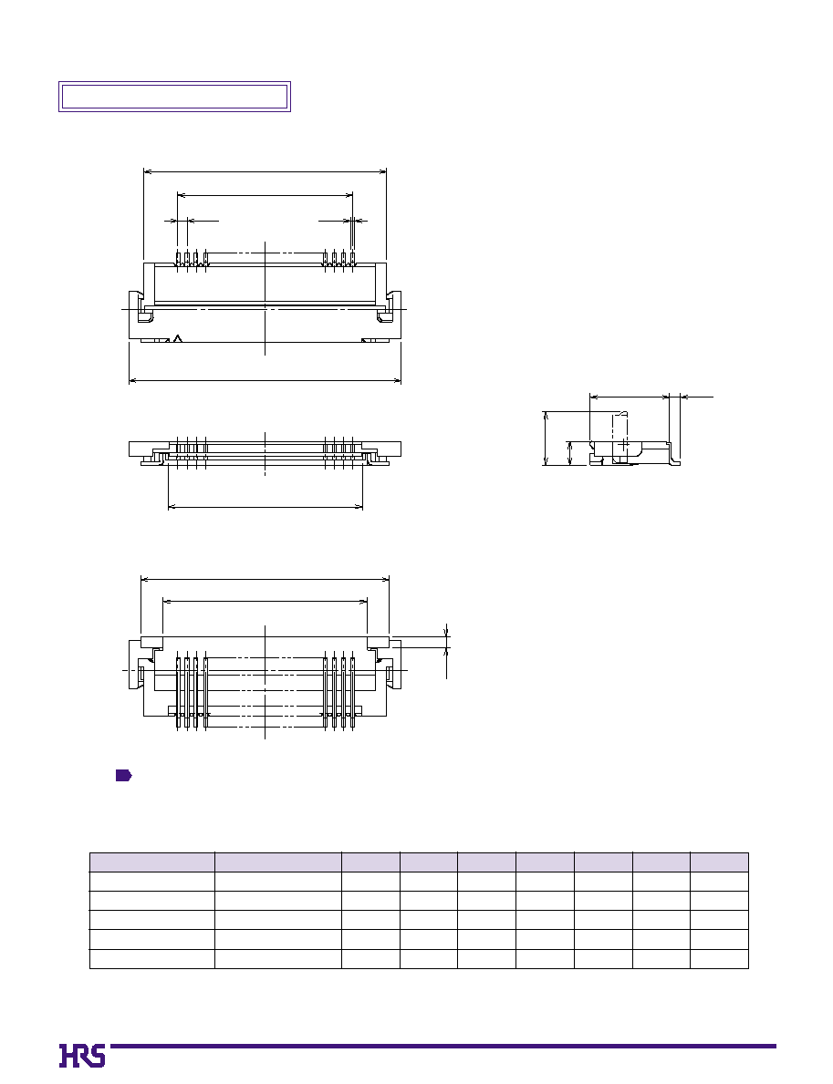
Note
The coplanarity of each lead and metal fitting is within 0.1.
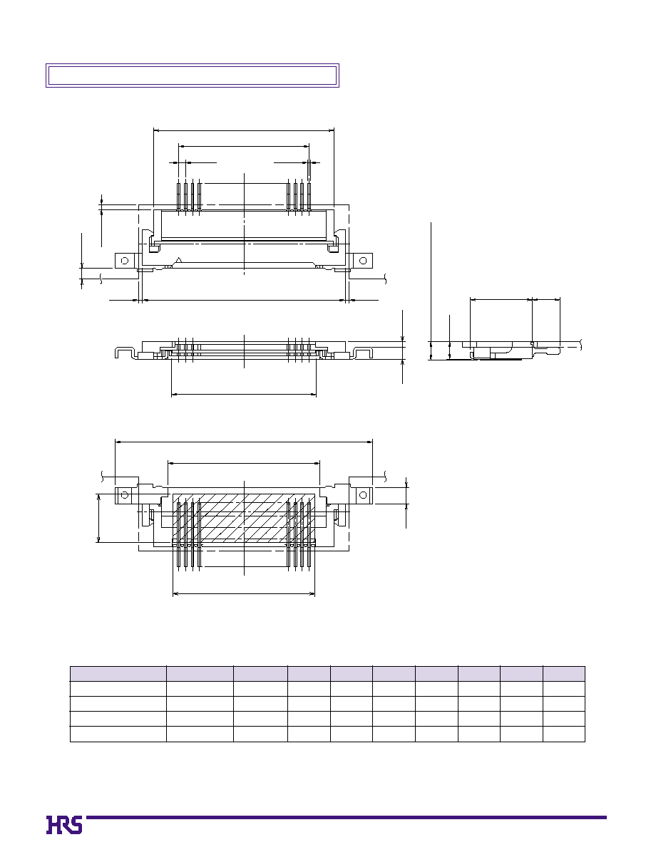
On-Board Type (FH17)
2.9
F
E
0.2
0.5
B
A
C
D
0.6
1.3
4.3
0.6
(mm)
Note:Embossed tape reel packaging(2,000 pieces/reel).
Order by number of reels.
Part Number
FH17-10S-0.5SH
FH17-15S-0.5SH
FH17-20S-0.5SH
FH17-24S-0.5SH
FH17-30S-0.5SH
586-0638-8
586-0657-2
586-0637-5
586-0645-3
586-0625-6
10
15
20
24
30
0
8.2
10.7
13.2
15.2
18.2
0
4.5
0
7.0
0
9.5
11.5
14.5
0
9.8
12.3
14.8
16.8
19.8
0
5.57
0
8.07
10.57
12.57
15.57
0
8.5
11.0
13.5
15.5
18.5
0
6.1
0
8.6
11.1
13.1
16.1
CL No.
Number of
Contacts
A
B
C
D
E
F
1
29
0
4.5
0
7.0
0
9.5
11.5
14.5
B
0
9.1
11.6
14.1
16.1
19.1
G
0
6.1
0
8.6
11.1
13.1
16.1
H
0
5.3
0
7.8
10.3
12.3
15.3
J
(mm)
Part Number
FH17-10S-0.5SH
FH17-15S-0.5SH
FH17-20S-0.5SH
FH17-24S-0.5SH
FH17-30S-0.5SH
586-0638-8
586-0657-2
586-0637-5
586-0645-3
586-0625-6
10
15
20
24
30
CL No.
Number of
Contacts
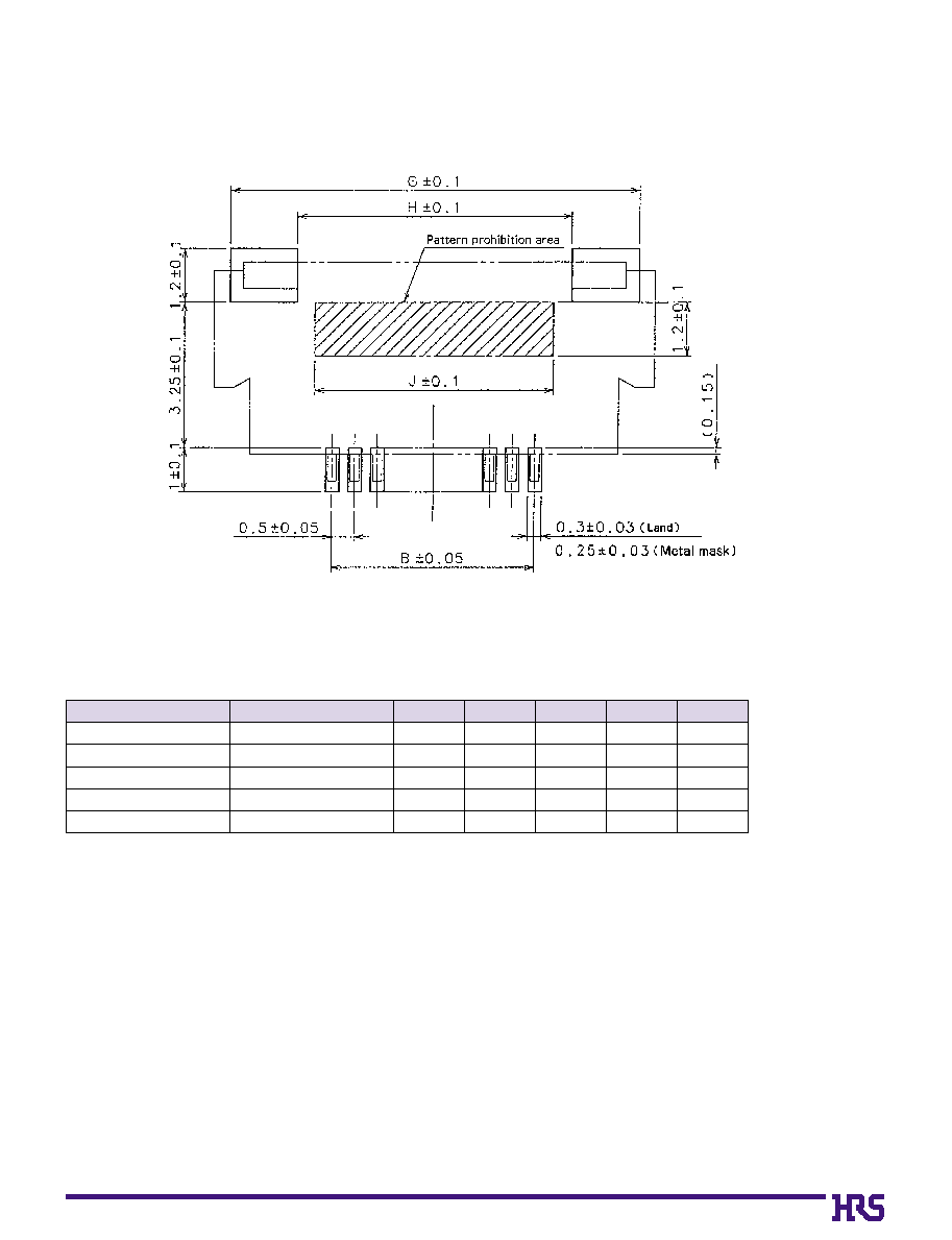
B
Recommended Land/ Metal Mask Dimensions (FH17)
*
Recommended metal mask thickness: t = 0.15
Note:Embossed tape reel packaging (2,000 pieces/reel).
Order by number of reels.
30
(0.4)
(3.5)
(0.35)
(0.8)
(1)
(0.3)
(0.3)
(0.2)
L
A
B
C
D
K
F
4.55
1.4 (Including polyamide tape)
1.2
1.3
2
0.5
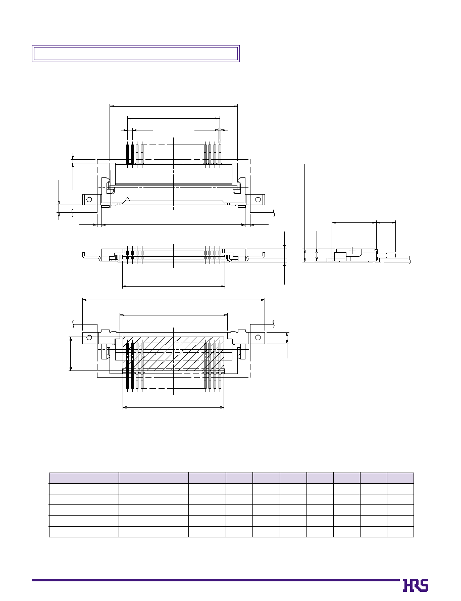
Note: The coplanarity of each lead and metal fitting is within 0.1.
Offset Standard Type (FH17L)
(mm)
Note:Embossed tape reel packaging (2,000 pieces/reel).
Order by number of reels.
Part Number
FH17L-
0
8S-0.5SH
FH17L-10S-0.5SH
FH17L-20S-0.5SH
FH17L-30S-0.5SH
586-0654-4
586-0650-3
586-0651-6
586-0652-9
0
8
10
20
30
0
7.2
0
8.2
13.2
18.2
0
3.5
0
4.5
0
9.5
14.5
0
8.8
0
9.8
14.8
19.8
0
4.57
0
5.57
10.57
15.57
12.8
13.8
18.8
23.8
0
5.1
0
6.1
11.1
16.1
0
4.4
0
5.4
10.4
15.4
CL No.
Number of
Contacts
A
B
C
D
K
F
L
31
(1)
(3.5)
(0.35)
(0.8)
(0.4)
(0.5)
(0.5)
(0.2)
L
A
B
C
D
K
F
4.55
1.4 (Including polyamide tape)
1.2
1.3
2
0.5
Note: The coplanarity of each lead and metal fitting is within 0.1.
Offset Reverse Type (FH17LR)
(mm)
Note:Embossed tape reel packaging (2,000 pieces/reel).
Order by number of reels.
Part Number
FH17LR-
0
8S-0.5SH
FH17LR-10S-0.5SH
FH17LR-20S-0.5SH
FH17LR-24S-0.5SH
FH17LR-30S-0.5SH
586-0666-3
586-0659-8
586-0660-7
586-0683-2
586-0661-0
0
8
10
20
24
30
0
7.2
0
8.2
13.2
15.2
18.2
CL No.
Number of
Contacts
A
0
3.5
0
4.5
0
9.5
11.5
14.5
B
0
8.8
0
9.8
14.8
16.8
19.8
C
0
4.57
0
5.57
10.57
12.57
15.57
D
12.8
13.8
18.8
20.8
23.8
K
0
5.1
0
6.1
11.1
13.1
16.1
F
0
4.4
0
5.4
10.4
12.4
15.4
L
32
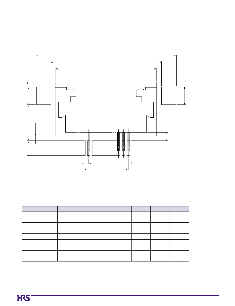
Note: The coplanarity of each lead and metal fitting is within 0.1.
B
Recommended Land/ Metal Mask Dimensions (FH17L and FH17LR)
M±0.1
N±0.1
P±0.1
B±0.05
0.5±0.05
1.8±0.1
1.8±0.1
3.65±0.1
1.5±0.1
0.25±0.03(Metal Mask)
0.3±0.03(Land)
* Recommended metal mask thickness: t=0.15
(0.85)
(0.5)
(mm)
Note:Embossed tape reel packaging (2,000 pieces/reel).
Order by number of reels.
Part Number
FH17L- 8S-0.5SH
FH17L- 10S-0.5SH
FH17L- 20S-0.5SH
FH17L- 30S-0.5SH
FH17LR-8S-0.5SH
FH17LR-10S-0.5SH
FH17LR-20S-0.5SH
FH17LR-24S-0.5SH
FH17LR-30S-0.5SH
586-0654-4
586-0650-3
586-0651-6
586-0652-9
586-0666-3
586-0659-8
586-0660-7
586-0683-2
586-0661-0
0
8
10
20
30
0
8
10
20
24
30
0
3.5
0
4.5
0
9.5
14.5
0
3.5
0
4.5
0
9.5
11.5
14.5
13.4
14.4
19.4
24.4
13.4
14.4
19.4
21.4
24.4
10.4
11.4
16.4
21.4
10.8
11.8
16.8
18.8
21.8
0
9.4
10.4
15.4
20.4
0
9.8
10.8
15.8
17.8
20.8
CL No.
Number of
Contacts
B
M
N
P
33
(mm)
Note:Embossed tape reel packaging (2,000 pieces/reel).
Order by number of reels.
Part Number
FH17-
10S-0.5SH
FH17-
15S-0.5SH
FH17-
20S-0.5SH
FH17-
24S-0.5SH
FH17-
30S-0.5SH
FH17L-
0
8S-0.5SH
FH17L- 10S-0.5SH
FH17L- 20S-0.5SH
FH17L- 30S-0.5SH
FH17LR-
0
8S-0.5SH
FH17LR-10S-0.5SH
FH17LR-20S-0.5SH
FH17LR-24S-0.5SH
FH17LR-30S-0.5SH
586-0638-8
586-0657-2
586-0637-5
586-0645-3
586-0625-6
586-0654-4
586-0650-3
586-0651-6
586-0652-9
586-0666-3
586-0659-8
586-0660-7
586-0683-2
586-0661-0
10
15
20
24
30
0
8
10
20
30
0
8
10
20
24
30
0
4.5
0
7.0
0
9.5
11.5
14.5
0
3.5
0
4.5
0
9.5
14.5
0
3.5
0
4.5
0
9.5
11.5
14.5
0
5.5
0
8.0
10.5
12.5
15.5
0
4.5
0
5.5
10.5
15.5
0
4.5
0
5.5
10.5
12.5
15.5
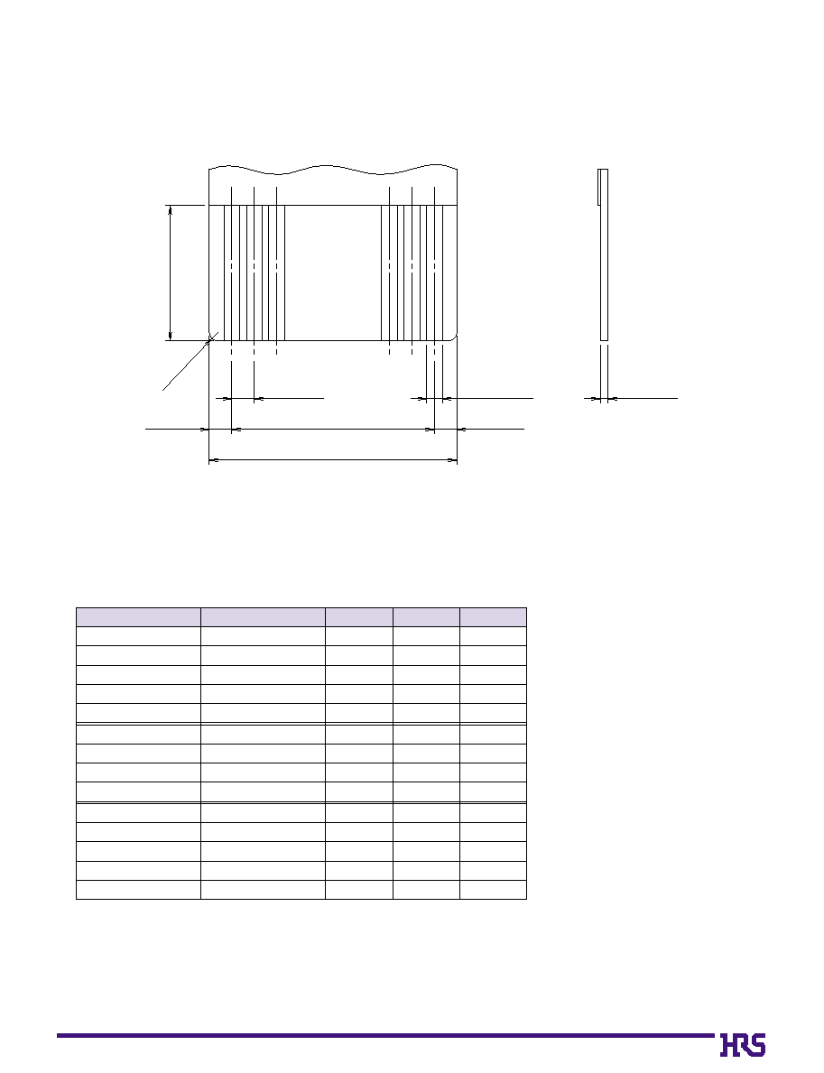
CL No.
Number of
Contacts
B
Q
*
A combination of polyamide and heat-hardened adhesive should be used for the stiffener material in
the case of single-sided FPC.
The copper foil of the rear surface should not be used in the case of double-sided FPC.
B
Recommended FPC Dimensions (FH17, FH17L, and FH17LR)
3MIN
0.5±0.05
B±0.05
0.5±0.1
0.5±0.1
Q±0.07
0.35±0.03
0.17
+0.03
≠ 0.04
2≠
R0.2
34
B
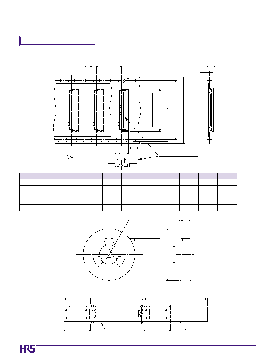
Packaging Specification
q
Embossed Carrier Tape Dimensions
q
Reel Dimensions
(mm)
Part Number
FH17-10S-0.5SH
FH17-15S-0.5SH
FH17-20S-0.5SH
FH17-24S-0.5SH
FH17-30S-0.5SH
586-0638-8
586-0657-2
586-0637-5
586-0645-3
586-0625-6
10
15
20
24
30
16
24
24
24
32
---------
---------
---------
---------
28.4
0
7.5
11.5
11.5
11.5
14.2
10.6
13.1
15.6
17.6
20.6
0
6.5
0
9.0
11.5
13.5
16.5
16.5
24.5
24.5
24.5
32.5
CL No.
Number of
Contacts
R
S
T
U
V
W
On-Board Type (FH17)
V
U
4.6
1.4
S
1.8
1.9
R
T
12
4
2
ÿ1.5
1.75
1.7
Unreeling direction
1.5
0.3
Flat surface for placement
with Automatic equipment
ÿ13
ÿ80
ÿ330
2
W
Empty section
End portion
Mounting portion
Embossed carrier tape
Leader area (400mm or more)
Empty section
Top cover tape
(10 pockets or more)
(10 pockets or more)

35
Standard Type
Reverse Type
Part Number
FH17LR-
0
8S-0.5SH
FH17LR-10S-0.5SH
FH17LR-20S-0.5SH
FH17LR-24S-0.5SH
FH17LR-30S-0.5SH
586-0666-3
586-0659-8
586-0660-7
586-0683-2
586-0661-0
0
8
10
20
24
30
24
24
32
32
44
----
----
28.4
28.4
40.4
11.5
11.5
14.2
14.2
20.2
13.8
14.8
19.8
21.8
24.8
24.5
24.5
32.5
32.5
44.5
CL No.
Number. of
Contacts
R
S
T
X
W
q
Embossed Carrier Tape Dimensions
S
R
X
T
2.8
5.6
1.9
Unreeling direction
1.5
1.75
±0.1
1.8
12
4
2
ÿ1.5
0.3
1.7
ÿ13
ÿ
80
ÿ
330
2
W
Blank portion
End portion
Mounting portion
Embossed carrier tape
Lead portion (400mm min.)
Blank portion
Top cover tape
(10 pockets min.)
(10 pockets min.)
q
Reel Dimensions
(mm)
(mm)
Offset Type (FH17L and FH17LR)
Part Number
FH17L-
0
8S-0.5SH
FH17L-10S-0.5SH
FH17L-20S-0.5SH
FH17L-30S-0.5SH
586-0654-4
586-0650-3
586-0651-6
586-0652-9
0
8
10
20
30
24
24
32
44
----
----
28.4
40.4
11.5
11.5
14.2
20.2
13.8
14.8
19.8
24.8
24.5
24.5
32.5
44.5
CL No.
Number. of
Contacts
R
S
T
X
W
Flat surface for placement
with Automatic equipment
36
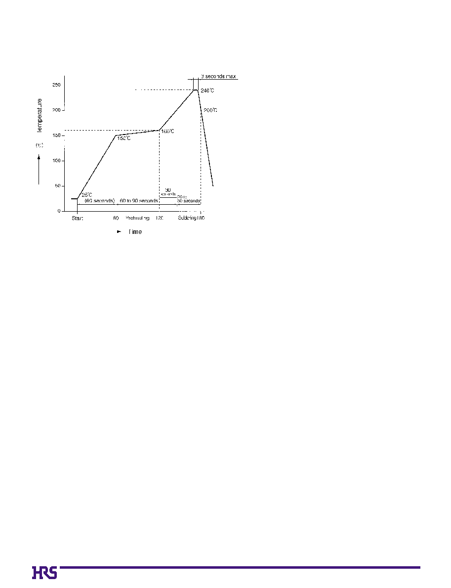
B
Recommended Temperature Profile
HRS test conditions
Solder method
:Reflow, IR/hot air
(Nihon Den-netsu Co., Ltd.'s
Part Number: SENSBY NR-2)
Environment
:Room air
Solder composition
:Paste, 63%Sn/37%Pb
(Senju Metal Industry, Co., Ltd.'sPart
Number: OZ63-201C-50-9)
Test board
:Glass epoxy 40mm80mm1.6mm thick
Land dimensions
:On-Board type 0.3mm1.0mm
Offset type 0.3mm1.5mm
Metal mask
:On-Board type
0.25mm1.0mm0.15mm thick
Offset type
0.25mm1.5mm0.15mm thick
This temperature profile is based on the above conditions.
\In individual applications the actual temperature may vary,
depending on solder paste type, volume/thickness and board
size/thickness. Consult your solder paste and equipment
manufacturer for specific recommendations.

37
Sumitomo Bakelite Co., Ltd. Flexible Printed Circuit Board Division
TEL:+81 3 5462 4191
5-8, Higashi-shinagawa 2-chome, Shinagawa-ku, Tokyo, Japan
FAX:+81 3 5462 4882
Fujikura Ltd. Electronics Global Marketing Department
TEL:+81 3 5606 1165
1-5-1, Kiba, Koto-ku, Tokyo, Japan
FAX:+81 3 5606 1530
NOK Corporation Sales Division Overseas Business Department
TEL:+81 3 3432 6976/8415
1-12-15, Shiba-Daimon, Minato-ku, Tokyo, Japan
FAX:+81 3 3432 3919
B
FH17 Series FPC Construction (Recommended Specifications)
1. Single-Sided FPC
2. Using Double-Sided FPC
3. Precautions
1. This specification is a recommendation for the construction of the FH17 Series FPC (t=0.17 +0.03/-0.04).
2. The FH17 Series are connectors for thin FPC which is beginning to be used in cameras and other miniature equipment.
Stiffener is not required for double-sided FPC which will be reflected in FPC cost reduction.
Please Note that in the case of single-sided FPC, stiffener is required, but the thickness dimension can be created easily.
For details about the construction, please contact the FPC/FFC manufacturers.
Note: Stiffener is not required for the double-sided FPC.
To prevent release of the lock due to FPC bending, please do not use copper foil on the rear side.
Material Name
Covering layer film
Cover adhesive
Surface treatment
Copper foil
Base adhesive
Base film
Reinforcement material adhesive
Stiffener
Polyamide 1 mil
Tin-lead plating
Cu
1oz
Polyamide 1 mil
Heat-hardened adhesive
Polyamide 2 mil
Total
25
25
5
35
18
25
30
50
163
Material
Thickness (
µ
m)
Material Name
Covering layer film
Cover adhesive
Surface treatment
Through hole copper
Copper foil
Base adhesive
Base film
Base adhesive
Copper foil
Cover adhesive
Covering layer film
Polyamide 1 mil
Tin-lead plating
Cu
Cu
1oz
Polyamide 1 mil
Cu
1oz
Polyamide 1 mil
Total
25
25
5
15
35
18
25
18
35
33
25
174
Material
Thickness (
µ
m)
FPC/FFC Manufactures' Contact List