
47
Low Profile 0.3mm Pitch Connectors For FPC
FH18 Series
s
Features
1. Low profile 0.3mm pitch FPC connectors
In response to continuous miniturization of products, the demand for
smaller contact spacing on connectors is increasing. Flexible printed
circuits(FPC) with contact pitch of 0.3mm are used with increased
frequency. FH18 series connectors fullfill this requirement. In
addition, these connectors occupy less board space and are lighter
than comparable connectors with contacts spaced at 0.5mm.
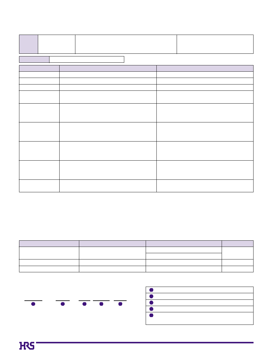
2. Improved Retention of FPC
Two types of contacts design are combined in the FH18 connector,
zero insertion force(ZIF) and low insertion force(LIF). Inserted FPC is
held in place by the LIF contact, allowing operator to close down the
actuator and engage the ZIF contacts to assure complete connection.
3. Easy to use Flip-Lock Actuator
Flip-lock (rotating type) ZIF mechanism enables good connectivity of
FPC by a simple operation and light force. No board space is required
for flip lock operation as compared to slide lock ZIF connectors.
4. Placement on Board
The leads are on two sides of the connector, spaced on 0.6mm and
are visible for solder joint inspection. Flat top surface of the connector
allows board placement with automated equipment.
5. Variety of Contact Positions
The connectors are available with 17,21,25,27,39,45 and 51 contacts.
s
Applications
Notebook computers, printers, PDAs, digital cameras and other
compact devices for interconnecting the main circuit board with the
LCD, PDP (Plasma Display),HDD or other device.
1.8mm height above
the mounting surface
*
LIF : Low insertion Force
*
ZIF : Zero insertion Force
Non ≠ ZIF Contact
FPC
Retention of FPC
FPC insertion
direction
LIF terminal contacts
Connection completed
ZIF contact
Actuator closed
1.8mm
48
s
Product Specifications
s
Material
Rating
Current rating 0.15A
Voltage rating 30V AC
Remarks
UL 94V-0
--------
--------
Part
Material
Finish
Insulator
Contact
Metal fitting
LCP
Phosphor bronze
Bronze
Color : Beige
Color : Black
Tin-lead plating
Tin-lead plating
Applicable FPC
t
=
0.2
±
0.03 Tin-lead plating (Note 4)
s
Ordering Information
FH18 - 27S - 0.3 SHW (05)
1
2
3
4
5
Series name
FH18
Number of contacts
17, 21, 25, 27, 39, 45, 51
Contact pitch
0.3mm
Contact style
SHW : SMT horizontal mounting type
Plating specifications No symbol : Tin-lead plating
(05) : Gold plating
1
2
3
4
5
Storage temperature range
-10
Á
to +50
Á
(Note 2)
Storage humidity range
Relative humidity 90% max.
(without condensation)
Operating temperature range
-40
Á
to +85
Á
(Note 1)
Operating humidity range
Relative humidity 90% max.
(without condensation)
100V DC
90V AC/1 minute
10 cycles
1mA
Frequency: 10 to 55 Hz, single amplitude of 0.75 mm,
2 hours in each of the 3 directions.
Acceleration of 490 m/s
2
, 11 ms duration,
sine half-wave waveform, 3 cycles in each of the 3 axis.
96 hours at temperature of 40Á and humidity of 90% to 95%
5 cycles under conditions as follows; Temperature:
-40
Á /
15
to
35
Á /
85
Á /
15
to
35
Á
,
Time: 30
/
5max.
/
30
/
5 max.(minutes)
Reflow: At the recommended temperature profile
Manual soldering: 350±5Á for 3 seconds
Item
1.Insulation resistance
2.Withstanding voltage
4.
Durability
(Insertion/withdrawal)
3.Contact resistance
5.Vibration
6.Shock
7.
Humidity
(Steady state)
8.Temperature cycle
9.Resistance to
soldering heat
Specification
50M
ohms
minimum
No flashover or insulation breakdown.
100m
ohms
maximum
Contact resistance : 100m
ohms
maximum
No damage, cracks, or parts dislocation.
No electrical discontinuity of 1µs or more
Contact resistance: 100m
ohms
maximum
No damage, cracks, or parts dislocation.
No electrical discontinuity of 1µs or more
Contact resistance: 100m
ohms
maximum
No damage, cracks, or parts dislocation.
Contact resistance: 100m
ohms
maximum
Insulation resistance: 50M
ohms
minimum
No damage, cracks, or parts dislocation.
Contact resistance: 100m
ohms
maximum.
Insulation resistance: 50M
ohms
minimum.
No damage, cracks, or parts dislocation.
No deformation of components affecting performance.
Conditions
Note 1: Includes temperature rise caused by current flow.
Note 2: The term "storage" refers to products stored for long period of time prior to mounting and use. Operating Temperature Range and
Humidity range covers nonconducting condition of installed connectors in storage, shipment or during transportation.
Note 3: When FPC is gold plated, the connector contacts should be also gold plated: Select the (05) specification.
49
B
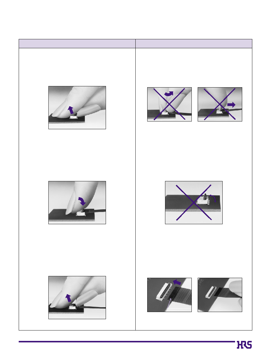
Connector Operating Instructions, precautions and recommendations
1.FPC Termination procedure. Connector
installed on the board.
1) Lift up the actuator. Use thumb or index finger.
2) Rotate down the actuator until firmly closed.
It is critical that the inserted FPC is not moved and
remains fully inserted. Should the FPC be moved,
open the actuator and repeat the process, starting
with Step 1 above.
2)
The connector will assure reliable performance
when the actuator is open to 130∞ maximum (see
fig.1) Do not exceed this angle, as this may cause
permanent damage to the connector.
2.FPC Removal
1) Lift up the actuator.
2) Carefully remove the FPC.
3) Assure that the FPC/FFC is fully inserted parallel
to mounting surface, with the exposed conductive
traces facing down.
1) Do not apply excessive force or use any type of
tool to operate the actuator.
90Á
Operation
Precautions
FPC conductive traces
Fig.1
50
0
* *
( 0.15
Indicates the number
of contacts
)
( 0.12 )
( 0.2 )
J
0.15 MAX
P=0.6
B
C
P=0.6
( 1.7 )
0.675
( 1.4 )
E : FPC slot dimension*
D
A
(2.45
)
4.1
0.5
0.5
1.8(Lead is included)
(3
)
1
2
Contact #1
Position indicator
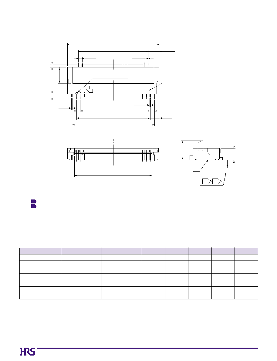
Notes
(1)
Indicates the distance from J surface.
The coplanarity of each lead and metal fitting within 0.1.(coplanarity : The distance between the lowest and highest land)
This connector uses LIF(Low Insertion Force) and ZIF(Zero Insertion Force)
contact design. Slight friction will be felt during insertion of FPC in the slot.
Full insertion of FPC is required for secure connection.
1
2
3
Unit: mm
Part Number
FH18-17S-0.3SHW
FH18-21S-0.3SHW
FH18-25S-0.3SHW
FH18-27S-0.3SHW
FH18-39S-0.3SHW
FH18-45S-0.3SHW
FH18-51S-0.3SHW
586-0684-5
586-0669-1
586-0685-8
586-0658-5
586-0646-6
586-0694-9
586-0671-3
17
21
25
27
39
45
51
0
7.6
0
8.8
10.0
10.6
14.2
16.0
17.8
0
4.2
0
5.4
0
6.6
0
7.2
10.8
12.6
14.4
0
4.8
0
6.0
0
7.2
0
7.8
11.4
13.2
15.0
0
6.15
0
7.35
0
8.55
0
9.15
12.75
14.55
16.35
0
5.4
0
6.6
0
7.8
0
8.4
12.0
13.8
15.6
CL No.
Number of contacts
A
B
C
D
E
Note : Embossed tape reel packaging (2,500 pieces/reel).
Order by number of reels.
51
0
4.2
0
5.4
0
6.6
0
7.2
10.8
12.6
14.4
B
0
4.8
0
6.0
0
7.2
0
7.8
11.4
13.2
15.0
C
0
5.4
0
6.6
0
7.8
0
8.4
12.0
13.8
15.6
E
Unit: mm
Part Number
FH18-17S-0.3SHW
FH18-21S-0.3SHW
FH18-25S-0.3SHW
FH18-27S-0.3SHW
FH18-39S-0.3SHW
FH18-45S-0.3SHW
FH18-51S-0.3SHW
586-0684-5
586-0669-1
586-0685-8
586-0658-5
586-0646-6
586-0694-9
586-0671-3
17
21
25
27
39
45
51
CL No.
Number of contacts
B
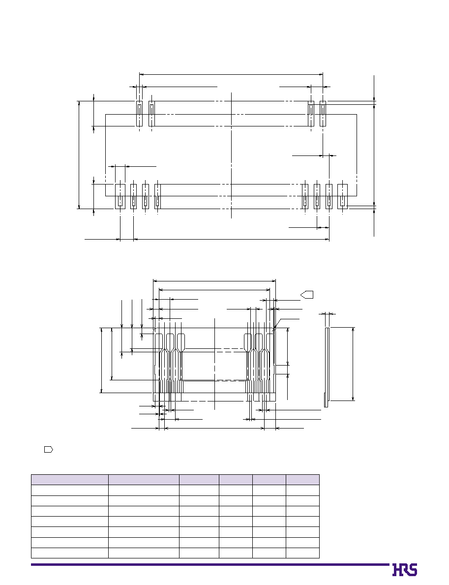
Recommended FPC Dimensions
0.25±0.05 (Metal mask)
B ±0.05
C ±0.05
0.3±0.05 (Land)
0.6±0.05
0.6 ±0.05
0.3 ±0.05
0.675 ±0.05
0.5 ±0.05
1.25
±0.05
1.25
±0.05
5.4
±0.05
(
0.15
)
(
5.1
)
(
0.15
)
7MIN
(Stiffener)
0.3±0.02
E ±0.05
(2- 0.07)
1.1
±0.15
1.3
±0.15
0.2
0.3
+0.04
_0.03
0.4
+0.04
_0.03
C ±0.03
0.3±0.07
(2-
2
)
(2-
0.5
)
( 0.1)
0.3
±0.15
0.2
0.05
0.6±0.02
B ±0.03
0.2 (Conductor width)
0.1 (Conductor gap)
0.6±0.07
2-R0.2
0.6±0.02
2.8
3.5
±0.3
0.2±0.03
2
B
Recommended Land/ Metal Mask Dimensions
*
Recommended metal mask thickness: t=0.15
Note 1
Polyimide and thermal hardening glue are a recommendation for the stiffener.
When drawing a plated lead, 0.3 is also permitted.
+0.04
-0.03
2
52
B
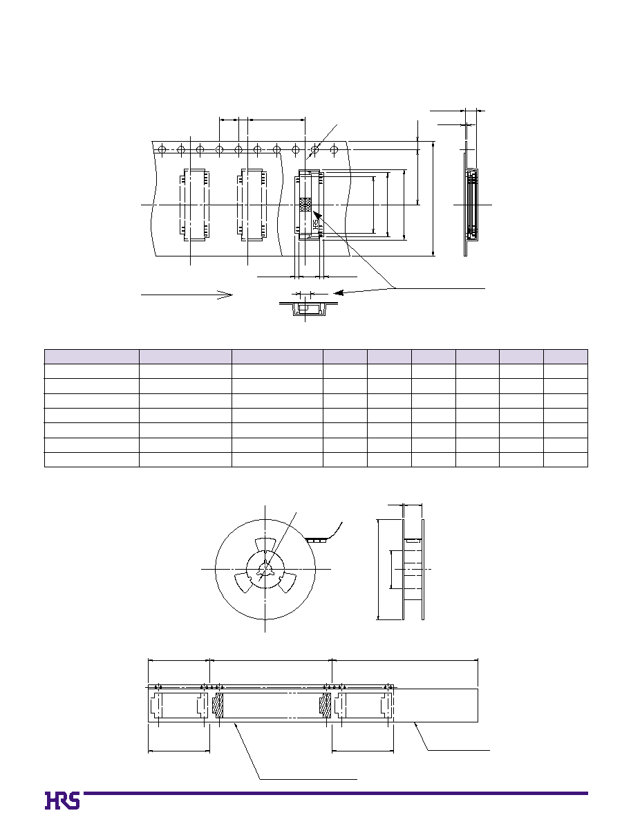
Packaging Specifications
q
Embossed Carrier Tape Dimensions
q
Reel Dimensions
**
(N
)
K
( 2.3 )
L
12
4
2
ÿ1.5
1.75
Unreeling direction
0.3
( 4.4)
( 0.85 )
( 0.85)
(Q
)
(M
)
2.45
Unit: mm
Part Number
FH18-17S-0.3SHW
FH18-21S-0.3SHW
FH18-25S-0.3SHW
FH18-27S-0.3SHW
FH18-39S-0.3SHW
FH18-45S-0.3SHW
FH18-51S-0.3SHW
586-0684-5
586-0669-1
586-0685-8
586-0658-5
586-0646-6
586-0694-9
586-0671-3
17
21
25
27
39
45
51
16
16
24
24
24
24
24
1
7.5
1
7.5
11.5
11.5
11.5
11.5
11.5
0
7.9
0
9.1
10.3
10.9
14.5
16.3
18.1
0
6.6
0
7.8
0
9.0
0
9.6
13.2
15.0
16.8
0
5.1
0
6.3
0
7.5
0
8.1
11.7
13.5
15.3
16.5
16.5
24.5
24.5
24.5
24.5
24.5
CL No.
Number of contacts
K
L
M
N
Q
R
Note:2,500 pieces per reel.
ÿ
13
ÿ
80
ÿ
380
2
(R)
(10 pockets min.)
(10 pockets min.)
End portion
Mounting portion
Embossed carrier tape
Blank portion
Lead portion (400 mm min.)
Blank portion
Top cover tape
Flat surface for placement
with Automatic equipment
53
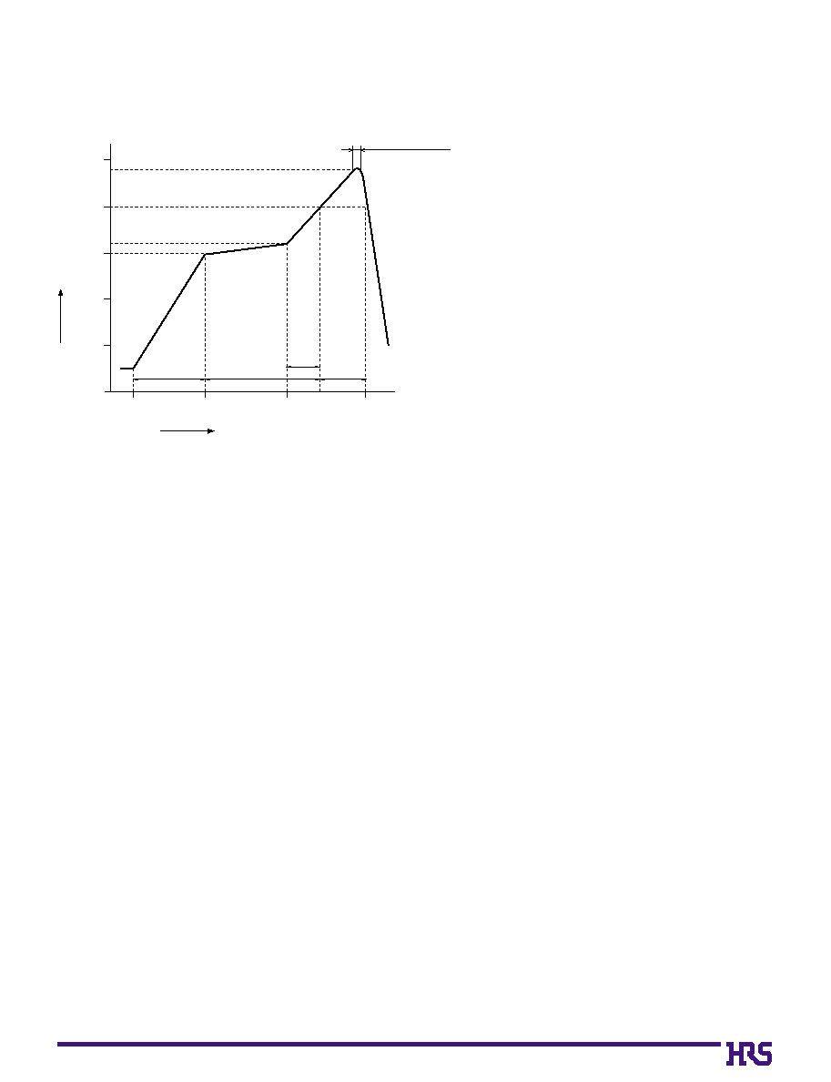
B
Recommended Temperature Profile
Start
Temperature
(Á
)
Time (seconds)
60
25Á (60 seconds)
(20-30 seconds)
(30 seconds)
60-90 seconds
Preheating
Soldering
0
50
100
150
150Á
160Á
240Á
200Á
3 seconds or less
200
250
120
180
HRS test conditions
Solder method
:Reflow, IR/hot air
(Nihon Den-netsu Co., Ltd.'s
Part Number: SENSBY NR-2)
Environment
:Room air
Solder composition
:Paste, 63%Sn/37%Pb
(Senju Metal Industry, Co., Ltd.'s Part
Number: OZ63-201C-50-9)
Test board
:Glass epoxy 70mm70mm1.6mm thick
Land dimensions
:0.3mm1.25mm
Metal mask
:0.25mm1.25mm0.15mm thick
This temperature profile is based on the above conditions.
In individual applications the actual temperature may vary,
depending on solder paste type, volume/thickness and board
size/thickness. Consult your solder paste and equipment
manufacturer for specific recommendations.

54
B
FH18 Series Construction (Recommended Specifications)
1. Single-Sided FPC
2. Using Double-Sided FPC
3. Precautions
1. This specification is a recommendation for the construction of the FH18 Series FPC (t=0.2
±
0.03).
2. For details about the construction, please contact the FPC/FFC manufacturers.
Note: Stiffener is not required for the double-sided FPC.
To prevent release of the lock due to FPC bending, please do not use copper foil on the rear side.
Material Name
Covering layer film
Cover adhesive
Surface treatment
Copper foil
Base adhesive
Base film
Reinforcement material adhesive
Stiffener
Polyamide 1 mil
Tin-lead plating
Cu
1oz
Polyamide 1 mil
Polyamide 3 mil
Total
25
25
5
35
25
25
30
75
195
Material
Thickness (
µ
m)
Material Name
Covering layer film
Cover adhesive
Surface treatment
Through hole copper
Copper foil
Base adhesive
Base film
Base adhesive
Copper foil
Cover adhesive
Cover layer film
Reinforcement material adhesive
Stiffener
Polyamide 1 mil
Tin-lead plating
Cu
Cu
1/2oz
Polyamide 1 mil
Cu
1/2oz
Polyamide 1 mil
Polyamide 1 mil
Total
25
25
5
15
18
18
25
18
18
25
25
25
25
199
Material
Thickness (
µ
m)
FPC/FFC Manufactures' Contact List
Sumitomo Bakelite Co., Ltd. Flexible Printed Circuit Board Division
TEL:+81 3 5462 4191
5-8, Higashi-shinagawa 2-chome, Shinagawa-ku, Tokyo, Japan
FAX:+81 3 5462 4882
Fujikura Ltd. Electronics Global Marketing Department
TEL:+81 3 5606 1165
1-5-1, Kiba, Koto-ku, Tokyo, Japan
FAX:+81 3 5606 1530
NOK Corporation Sales Division Overseas Business Department
TEL:+81 3 3432 6976/8415
1-12-15, Shiba-Daimon, Minato-ku, Tokyo, Japan
FAX:+81 3 3432 3919