38
0.5mm pitch, 0.9mm above the board, Flexible Printed Circuit & Flexible Flat Cable Connectors
FH19 & FH19S Series
s
Features
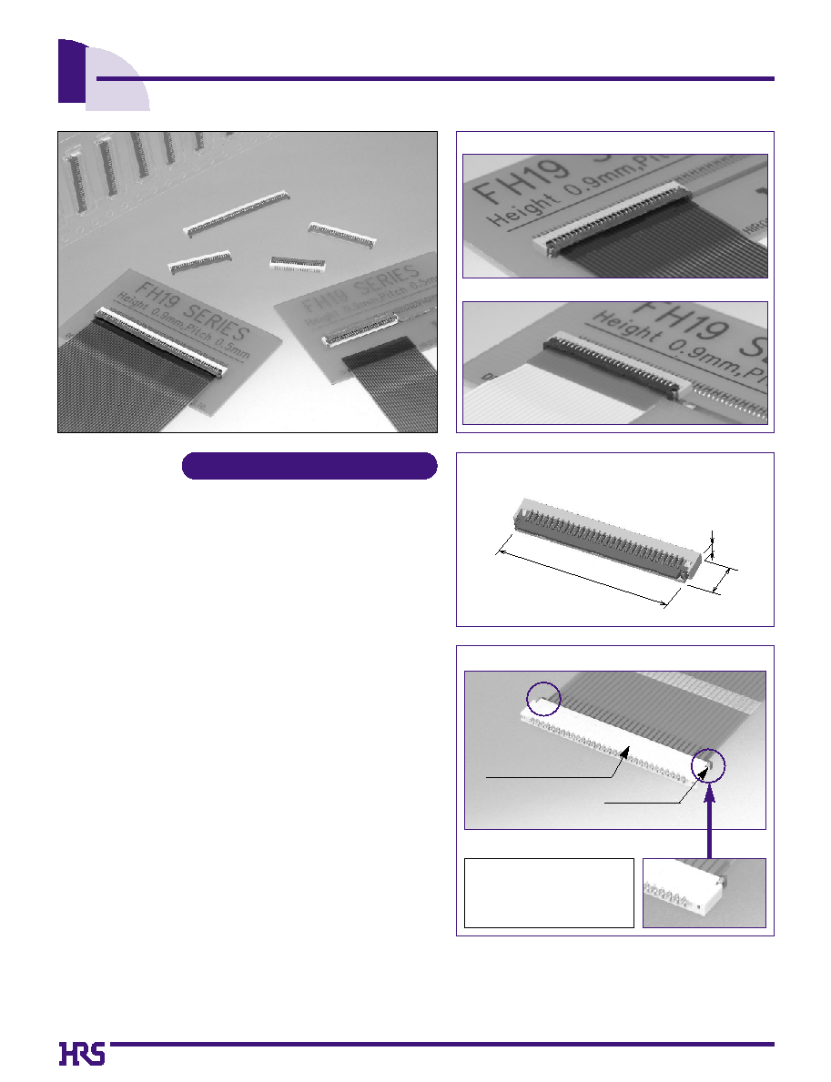
1. Low-profile 0.5mm pitch FPC, FFC Connectors
Miniaturization of portable equipment and personal mobile
devices has created increased demand for a low profile,
high density, and high reliability connectors.
*
The design of this connector has been made thinner and
smaller, with a height of 0.9mm and width of 3mm.
[As of August 2002, this is the smallest connector of this
type available on the market !]
*
PCB footprint: Reduced approximately 48% (as compared with
Hirose Electric's 0.5mm pitch FH12 Series connectors)
*
Connector weight: Reduced approximately 78% (as compared
with Hirose Electric's 0.5mm pitch FH12 Series connectors)
2. Conductive traces on the PCB can be designed to
run under the connector
All bottom surface of the connector is solid, without any
exposure of the contact.
3. Proven Flip-Lock Actuator System assures
easy and reliable operation
Rotating actuator permits easy insertion and reliable
connection with the FPC & FFC.
Tactile sensation confirms complete mechanical locking of
the actuator and the electrical connection.
4. Accepts 0.2mm & 0.3mm thick FPC, FFC
Accepts 0.2mm & 0.3mm thick FPC, FFC, easy inserted in
the connector.
The connector will also terminate successfully with 0.2mm
thick Flat Flexible Cable (FFC).
5. Designed for placement with automatic equipment
Packaged in embossed tape, on reel.
One reel contains 5,000 pieces.
6. Environmental considerations
The center cores of the embossed tape reels are made of
paper, unlike typical cores made of styrofoam.
s
Applications
Notebook PC's, PDA's, digital cameras and other
compact devices requiring interconnections of the
main circuit board with the LCD, plasma display
(PDP), HDD or other devices.
0.9mm
3mm
17mm
FPC ∑ FFC
FPC ∑ FFC
FPC ∑ FFC
FPC ∑ FFC
FPC ∑ FFC
FPC ∑ FFC
FPC ∑ FFC
FPC ∑ FFC
FPC ∑ FFC
FPC ∑ FFC
FPC ∑ FFC
FPC ∑ FFC
FPC ∑ FFC
FPC ∑ FFC
FPC ∑ FFC
FPC ∑ FFC
FPC ∑ FFC
q
Enclosed construction
q
0.9mm Height incorporates the Flip-Lock System
(30pos. Type)
q
Metal Fittings (Leadless Type)
Absence of protrusions from
the connector helps in design
of miniaturized devices.
Metal fittings
(Leadless)
Enclosed construction
(No exposed contacts.)
FH19 Series ≠ FPC, FFC thickness: 0.2
±
0.03mm
Actuator color: Dark brown
Actuator color: Black
FH19S Series ≠ FPC, FFC thickness: 0.3
±
0.03mm
World's smallest & lightest
World's smallest & lightest
39
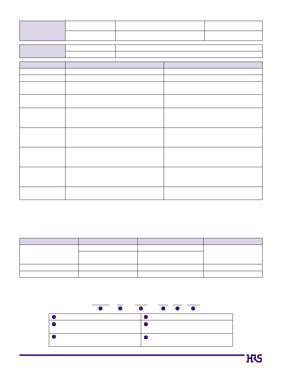
FH19 S - 30S - 0.5 SH (05)
1
2
4
5
3
6
s
Product Specifications
Rating
Current rating 0.5 A DC
Voltage rating 50 V AC
Operating temperature range
-55
Á
to +80
Á
(Note 1)
Operating humidity range
Relative humidity 90% max. (No condensation)
Storage temperature range
-10
Á
to +50
Á
(Note 2)
Storage humidity range
Relative humidity 90% max.
s
Materials
LCP
Color: Beige
Insulator
PPS
UL94V-0
Contacts
Phosphor bronze
Tin-lead plating (Note 3)
-------
Metal fittings
Phosphor bronze
Pure tin reflow plating
-------
Part Material
Finish
Remarks
Note 1: Includes temperature rise caused by current flow.
Note 2: The term "storage" refers to products stored for long period of time prior to mounting and use. Operating Temperature Range and
Humidity range covers non- conducting condition of installed connectors in storage, shipment or during transportation.
Note 3: When FPC is gold plated, the connector contacts should be also gold plated: Select the (05) specification.
Item
Specification
Conditions
1. Insulation resistance 500 M ohms min.
100 V DC
2. Withstanding voltage No flashover or insulation breakdown
150 V AC/1 minute
3. Contact resistance
100 m ohms max.
1 mA
*
Including FPC/FFC conductor resistance
4. Durability
Contact resistance: 100 m ohms max.
20 cycles
(insertion/ withdrawal)
No damage, cracks, or parts dislocation.
No electrical discontinuity of 1
µ
s or more.
5. Vibration
Contact resistance: 100 m ohms max.
No damage, cracks, or parts dislocation.
No electrical discontinuity of 1
µ
s. min.
6. Shock
Contact resistance: 100 m ohms max.
No damage, cracks, or parts dislocation.
7. Humidity
Contact resistance: 100 m ohms max.
(Steady state)
Insulation resistance: 100 M ohms min.
No damage, cracks, or parts dislocation.
Contact resistance: 100 m ohms max.
8. Temperature cycle
Insulation resistance: 100 M ohms min.
No damage, cracks, or parts dislocation.
9. Resistance to
No deformation of components affecting performance.
Reflow: At the recommended temperature profile
soldering heat
Manual soldering: 350
Á±
5
Á
for 5 seconds
96 hours at temperature of 40
Á
and humidity of
90 to 95%
Temperature: -40
Á /
+15
Á
to +35
Á /
+85
Á /
+15
Á
to +35
Á
Time: 30
/
2 to 3
/
30
/
2 to 3(Minutes)
5 cycles
Color: Dark brown (FH19 Series)
Color: Black (FH19S Series)
Acceleration of 981 m/s
2
, 6 ms duration, sine half-
wave waveform, 3 cycles in each of the 3 axis.
Frequency: 10 to 55 Hz, single amplitude of
0.75mm, 2 hours in each of the 3 directions
s
Ordering information
Series name :
FH19
Blank :
FPC,FFC thickness : 0.2mm
S :
FPC,FFC thickness : 0.3mm
No. of contacts :
4 to 50
Contact pitch :
0.5mm
Terminal type
SH: SMT horizontal mounting type
Plating specifications :
(05): Gold plating
(51): Tin-lead plating
1
4
2
5
3
6
Recommended
FPC, FFC
FH19 Series
FH19S Series
Thickness: = 0.2
±
0.03mm Tin-lead plating (Note 3)
Thickness: = 0.3
±
0.03mm Tin-lead plating (Note 3)
40
B
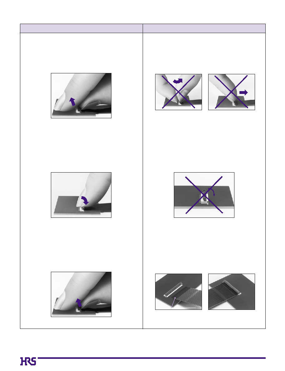
Connector Operating Instructions, Precautions and Recommendations
Operation
Precautions
FPC conductor surface
(Bottom side)
1. FPC/FFC Termination procedure.
Connector installed on the board.
1) Lift up the actuator. Use thumb or index finger.
2) Rotate down the actuator until firmly closed.
It is critical that the inserted FPC/FFC is not moved
and remains fully inserted. Should the FPC/FFC be
moved, open the actuator and repeat the process,
starting with Step 1 above.
2)
The connector will assure reliable performance
when the actuator is open to 130∞ maximum (see
fig.1) Do not exceed this angle, as this may cause
permanent damage to the connector.
2. FPC/FFC Removal
1) Lift up the actuator.
2) Carefully remove the FPC/FFC.
3) Assure that the FPC/FFC is fully inserted parallel
to mounting surface, with the exposed conductive
traces facing down.
1) Do not apply excessive force or use any type of
tool to operate the actuator.
41
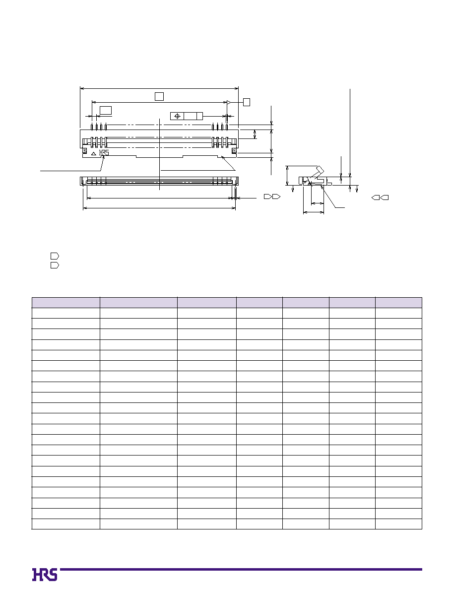
0
0
0.15 G
G
Number of contacts
Number of contacts indicator
(
2
.1
)
0.9 (Including contact terminal leads)
0.15MAX
0.15MAX
D
1.3
2.15
(1)
2.5
0
.5
(
0
.5
)
0.5
B
A
(C: FPC insertion area dimension)
( 0.15 )
(0.15)
E
Polarizing mark indicator
A
* *
1
2
1
2
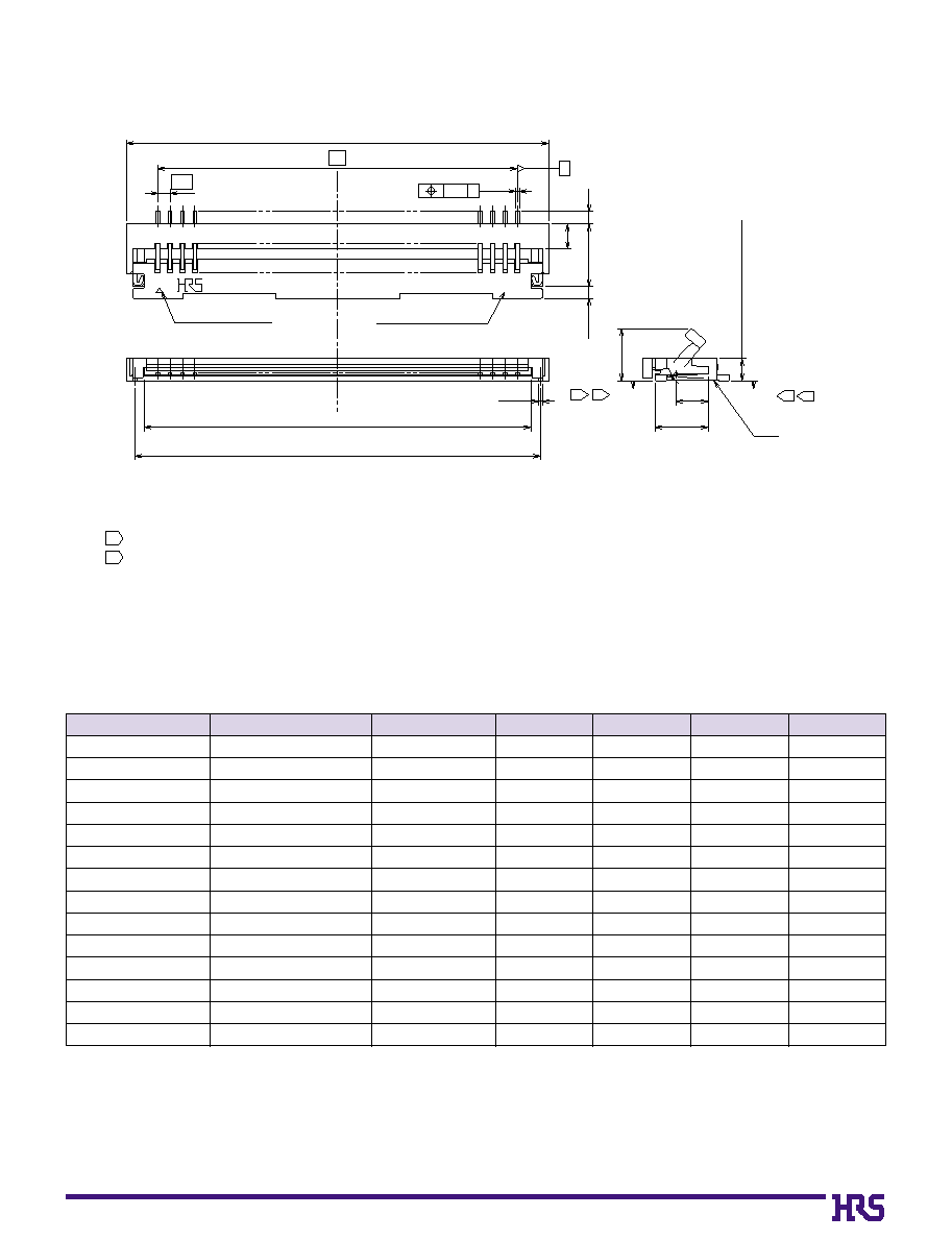
s
Connector Dimension
[FH19 Series]
Unit: mm
Note: Embossed tape reel packaging (5,000 pieces/reel) .
Order by number of reels.
Part Number
FH19-4S-0.5SH(51)
FH19-6S-0.5SH(51)
FH19-8S-0.5SH(51)
FH19-9S-0.5SH(51)
FH19-13S-0.5SH(51)
FH19-15S-0.5SH(51)
FH19-17S-0.5SH(51)
FH19-20S-0.5SH(51)
FH19-21S-0.5SH(51)
FH19-24S-0.5SH(51)
FH19-27S-0.5SH(51)
FH19-30S-0.5SH(51)
FH19-40S-0.5SH(51)
FH19-50S-0.5SH(51)
586-1009-8-51
Reserved for product expansion
586-1012-2-51
586-1006-0-51
586-1001-6-51
586-1004-4-51
586-1007-2-51
586-1002-9-51
586-1015-0-51
586-1011-0-51
586-1000-3-51
586-1003-1-51
586-1008-5-51
586-1005-7-51
4
6
8
9
13
15
17
20
21
24
27
30
40
50
0
4.0
0
5.0
0
6.0
0
6.5
0
8.5
0
9.5
10.5
12.0
12.5
14.0
15.5
17.0
22.0
27.0
0
1.5
0
2.5
0
3.5
0
4.0
0
6.0
0
7.0
0
8.0
0
9.5
10.0
11.5
13.0
14.5
19.5
24.5
0
2.57
0
3.57
0
4.57
0
5.07
0
7.07
0
8.07
0
9.07
10.57
11.07
12.57
14.07
15.57
20.57
25.57
0
3.35
0
4.35
0
5.35
0
5.85
0
7.85
0
8.85
0
9.85
11.35
11.85
13.35
14.85
16.35
21.35
26.35
CL No.
Number of Contacts
A
B
C
D
Notes
The coplanarity of each terminal lead and metal fitting is within 0.1
The contact terminal lead position indicates the dimension from the E surface, the bottom surface of the insulator body.
The connector is supplied in embossed tape packaging. For details see the Packaging Specifications.
Any discoloration of the plastic compound will NOT AFFECT form, fit or function of the connector.
1
2
3
4
42
1
2
1
2
0.15 G
0
0
0.15MAX
G
Number of contacts
0.15MAX
D±0.1
0.5
(1)
2.5
(0.5)
(1.3)
2.15
(0.03)
0.9 (Including contact terminal leads)
(2.1)
E
0.5
B
A
(C: FPC insertion area dimension)
(0.15)
(0.15)
Number of contacts indicator.
Polarizing mark indicator
* *
A
[FH19S Series]
Notes
The coplanarity of each terminal lead and metal fitting is within 0.1
The contact terminal lead position indicates the dimension from the E surface, the bottom surface of the insulator body.
The connector is supplied in embossed tape packaging. For details see the Packaging Specifications.
Any discoloration of the plastic compound will NOT AFFECT form, fit or function of the connector.
1
2
3
4
Unit: mm
Note: Embossed tape reel packaging (5,000 pieces/reel) .
Order by number of reels.
Part Number
FH19S-4S-0.5SH(51)
FH19S-5S-0.5SH(51)
FH19S-6S-0.5SH(51)
FH19S-9S-0.5SH(51)
FH19S-10S-0.5SH(51)
FH19S-12S-0.5SH(51)
FH19S-13S-0.5SH(51)
FH19S-14S-0.5SH(51)
FH19S-16S-0.5SH(51)
FH19S-17S-0.5SH(51)
FH19S-18S-0.5SH(51)
FH19S-20S-0.5SH(51)
FH19S-21S-0.5SH(51)
FH19S-22S-0.5SH(51)
FH19S-24S-0.5SH(51)
FH19S-26S-0.5SH(51)
FH19S-27S-0.5SH(51)
FH19S-30S-0.5SH(51)
FH19S-32S-0.5SH(51)
FH19S-45S-0.5SH(51)
FH19S-50S-0.5SH(51)
586-1119-6-51
586-1115-5-51
Reserved for product expansion
586-1120-5-51
586-1118-3-51
586-1105-1-51
Reserved for product expansion
586-1113-0-51
586-1112-7-51
586-1100-8-51
586-1110-1-51
586-1101-0-51
Reserved product expansion
586-1108-0-51
586-1102-3-51
586-1104-9-51
586-1103-6-51
586-1109-2-51
586-1121-8-51
586-1111-4-51
586-1107-7-51
4
5
6
9
10
12
13
14
16
17
18
20
21
22
24
26
27
30
32
45
50
0
4.0
0
4.5
0
5.0
0
6.5
0
7.0
0
8.0
0
8.5
0
9.0
10.0
10.5
11.0
12.0
12.5
13.0
14.0
15.0
15.5
17.0
18.0
24.5
27.0
0
1.5
0
2.0
0
2.5
0
4.0
0
4.5
0
5.5
0
6.0
0
6.5
0
7.5
0
8.0
0
8.5
0
9.5
10.0
10.5
11.5
12.5
13.0
14.5
15.5
22.0
24.5
0
2.57
0
3.07
0
3.57
0
5.07
0
5.57
0
6.57
0
7.07
0
7.57
0
8.57
0
9.07
0
9.57
10.57
11.07
11.57
12.57
13.57
14.07
15.57
16.57
23.07
25.57
0
3.35
0
3.85
0
4.35
0
5.85
0
6.35
0
7.35
0
7.85
0
8.35
0
9.35
0
9.85
10.35
11.35
11.85
12.35
13.35
14.35
14.85
16.35
17.35
23.85
26.35
CL No.
Number of Contacts
A
B
C
D
43
Unit: mm
0
4
0
5
0
6
0
8
0
9
10
12
13
14
15
16
17
18
20
0
4.0
0
4.5
0
5.0
0
6.0
0
6.5
0
7.0
0
8.0
0
8.5
0
9.0
0
9.5
10.0
10.5
11.0
12.0
0
1.5
0
2.0
0
2.5
0
3.5
0
4.0
0
4.5
0
5.5
0
6.0
0
6.5
0
7.0
0
7.5
0
8.0
0
8.5
0
9.5
0
3.1
0
3.6
0
4.1
0
5.1
0
5.6
0
6.1
0
7.1
0
7.6
0
8.1
0
8.6
0
9.1
0
9.6
10.1
11.1
0
3.9
0
4.4
0
4.9
0
5.9
0
6.4
0
6.9
0
7.9
0
8.4
0
8.9
0
9.4
0
9.9
10.4
10.9
11.9
0
2.5
0
3.0
0
3.5
0
4.5
0
5.0
0
5.5
0
6.5
0
7.0
0
7.5
0
8.0
0
8.5
0
9.0
0
9.5
10.5
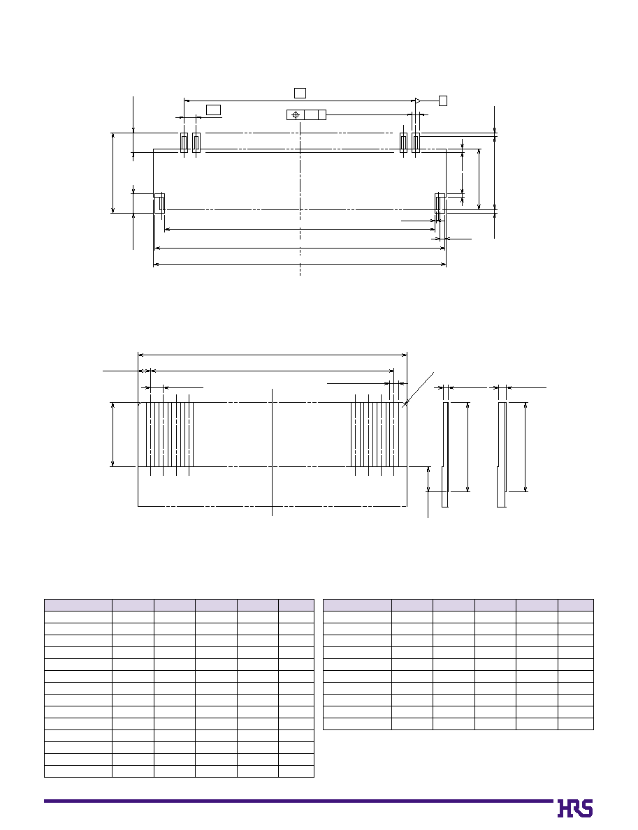
Number of Contacts
A
J
B
K
L
B
0.3±0.05 (Land)
0.5
0.8±0.05
0.25±0.05 (Metal mask)
0.1 H
H
Number of contacts
(0.15)
(0.15)
(0.15)
(0.15)
(3)
(2.5)
(A)
J±0.1
K±0.1
0.8±0.05
3.3±0.05
(0.2)
(0.05)
(X
)
0.2±0.03
3.5 min. (Stiffener)
0.3±0.03
3.5 min. (Stiffener)
2-
R0.2
0.5±0.07
B±0.03
0.5±0.03
L±0.05
FH19 Series
FH19S Series
0.35±0.03(FPC)
0.3±0.03(FFC)
2.5±0.3
(Area with removed covering film layer)
B
Recommended PCB Land and Metal Mask Dimensions
[Common to FH19 & FH19S Series]
B
Recommended FPC, FFC Dimensions
[Common to FH19 & FH19S Series]
Recommended metal mask thickness: 0.10 mm.
Note1: Polyamide and a thermally hardened adhesive is recommended as the materials for the stiffener.
Note2: Y dimension should be 1.5mm min., and X dimension should be 1.5mm for improved flexibility of FPC.
Unit: mm
21
22
24
26
27
30
32
40
45
50
12.5
13.0
14.0
15.0
15.5
17.0
18.0
22.0
24.5
27.0
10.0
10.5
11.5
12.5
13.0
14.5
15.5
19.5
22.0
24.5
11.6
12.1
13.1
14.1
14.6
16.1
17.1
21.1
23.6
26.1
12.4
12.9
13.9
14.9
15.4
16.9
17.9
21.9
24.4
26.9
11.0
11.5
12.5
13.5
14.0
15.5
16.5
20.5
23.0
25.5
Number of Contacts
A
J
B
K
L
44
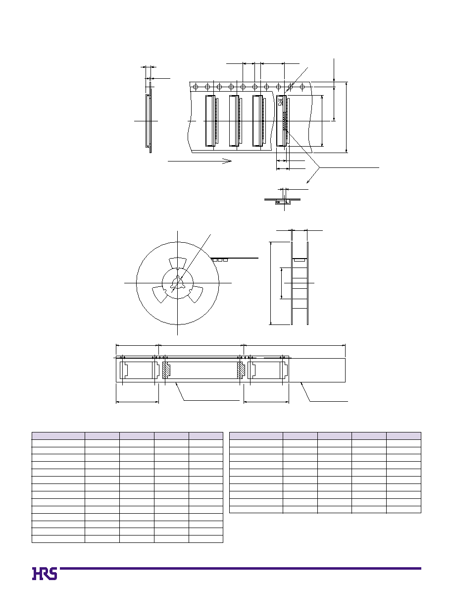
Unreeling direction
±0.3
±0.1
(0.3)
1.75±0.1
(1)
8±0.1
2±0.15
4±0.1
Flat surface for placement
with Automatic equipment
ÿ1.5
+
0.1
0
(
)
(1.7)
(3.3)
(4.3)
End portion
Mounting portion
Embossed carrier tape
Blank portion
Lead portion (400 mm min.)
Blank portion
Top cover tape
(ÿ13)
(ÿ380)
(ÿ80)
(2)
(R)
(10 pockets min.)
(10 pockets min.)
B
Packaging Specifications
[Common to FH19 & FH19S Series]
q
Reel Dimensions
Notes: 5,000 pieces per reel.
Embossed tape 32 mm or wider will have perforated feed holes on two sides.
q
Embossed Carrier Tape Dimensions
Unit: mm
0
4
0
5
0
6
0
8
0
9
10
12
13
14
15
16
17
18
20
16
16
16
16
16
16
16
16
16
16
24
24
24
24
0
7.5
0
7.5
0
7.5
0
7.5
0
7.5
0
7.5
0
7.5
0
7.5
0
7.5
0
7.5
11.5
11.5
11.5
11.5
0
4.3
0
4.8
0
5.3
0
6.3
0
6.8
0
7.3
0
8.3
0
8.8
0
9.3
0
9.8
10.3
10.8
11.3
12.3
16.5
16.5
16.5
16.5
16.5
16.5
16.5
16.5
16.5
16.5
24.5
24.5
24.5
24.5
Number of Contacts
M
Q
N
R
Unit: mm
21
22
24
26
27
30
32
40
45
50
24
24
24
24
24
24
32
44
44
44
11.5
11.5
11.5
11.5
11.5
11.5
14.2
20.2
20.2
20.2
12.8
13.3
14.3
15.3
15.8
17.3
18.3
22.3
24.8
27.3
24.5
24.5
24.5
24.5
24.5
24.5
32.5
44.5
44.5
44.5
Number of Contacts
M
Q
N
R
45
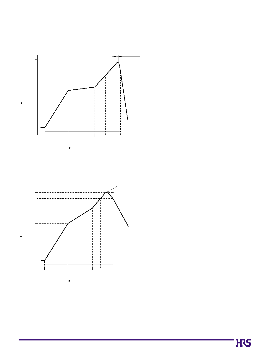
B
Recommended Temperature Profile
[For FH19 & FH19S Series]
HRS test conditions
Solder method
:Reflow, IR/hot air
(Nihon Den-netsu Co., Ltd.'s
Part Number: SENSBY NR-2)
Environment
:Room air
Solder composition
:Paste, 63%Sn/37%Pb
(Senju Metal Industry, Co., Ltd.'s Part
Number: OZ63-201C-50-9)
Test board
:Glass epoxy 45mm100mm1.6mm thick
Land dimensions
:0.3mm0.8mm
Metal mask
:0.25mm0.8mm0.1mm thick
This temperature profile is based on the above conditions.
In individual applications the actual temperature may vary,
depending on solder paste type, volume/thickness and board
size/thickness. Consult your solder paste and equipment
manufacturer for specific recommendations.
Start
Temperature(Á)
Time (Seconds)
60
25Á
(60 sec.)
(20 sec.
to 30 sec.)
(30 sec.)
60 sec. to 90 sec.
Preheating
Soldering
0
50
100
150
150Á
160Á
240Á
200Á
5 sec. Max.
200
250
120
q
Using Typical Solder Paste
HRS test condition
Solder method
:Reflow, IR/hot air
(Nihon Den-netsu Co., Ltd.'s
Part Number: SENSBY NR-2)
Environment
:Room air
Solder composition
:Paste, 96.5%Sn/3.0%Ag/0.5%Cu
(Senju Metal Industry, Co., Ltd.'s Part
Number:M705-221CM5-42-10.5)
Test board
:Glass epoxy 45mm100mm1.6mm thick
Land dimensions
: 0.3mm0.8mm
Metal mask
:0.25mm0.8mm0.1mm
In individual applications the actual temperature may vary,
depending on solder paste type, volume/thickness and board
size/thickness. Consult tour solder paste and equipment
manufacturer for specific recommendations.
MAX 250Á
Start
Time (Seconds)
60
25Á (60 sec.)
(60 sec.)
90 sec. to 120 sec.
Preheating
Soldering
0
50
100
150
150Á
200Á
230Á
200
250
120
Temperature(Á)
q
Using Lead-free Solder paste
46
B
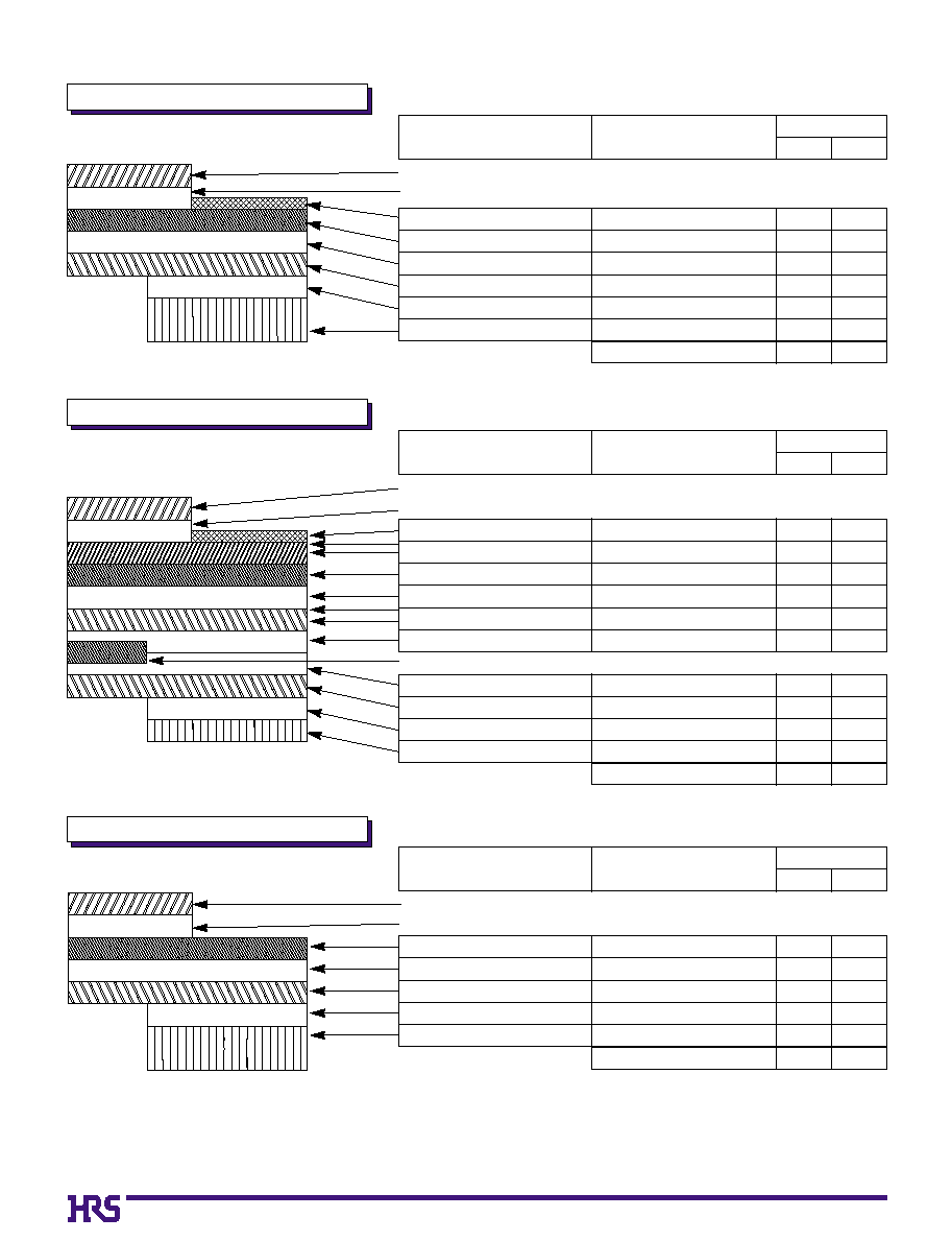
FH19 & FH19S Series FPC/FFC Construction (Recommended Specifications)
1. Using Single-sided FPC
2. Dual-sided FPC
Note 1: The 0.2mm thick FFC is the 0.3mm thick FFC with different stiffener.
Note 2: This specification is a recommendation for the FH19, FH19S Series connectors using FPC/FFC 0.2/0.3
±
0.03mm thick.
3. Using FFC (Flexible Flat Cable)
FPC : Flexible Printed Circuit
Material Name
Surface treatment
Copper foil
Base adhesive
Base film
Reinforcement material adhesive
Stiffener
Material
Thickness (
µ
m)
FH19
FH19S
Tin-lead plating
Cu
1oz
Polyamide
1 mil thick
Heat-hardened adhesive
Polyamide
3 mil thick
Total
Covering film layer.
Cover adhesive
Polyamide
1 mil thick
5
35
25
25
30
75
195
5
35
25
25
30
175
295
25
25
25
25
FPC : Flexible Printed Circuit
Covering layer film
Cover adhesive
Surface treatment
Through-hole copper
Copper foil
Base adhesive
Base film
Base adhesive
Copper foil
Cover adhesive
Covering layer film
Reinforcement material adhesive
Stiffener
Cu
1
/
2oz
Polyamide
1 mil thick
Heat-hardened adhesive
Polyamide
1 mil thick
Total
18
25
25
25
25
199
18
25
25
50
100
299
Polyamide
1 mil thick
Tin-lead plating
Cu
Cu
1
/
2oz
Polyamide
1 mil thick
25
25
5
15
18
18
25
18
25
25
5
15
18
18
25
18
Material Name
Material
Thickness (
µ
m)
FH19
FH19S
FFC : Flexible Flat Cable
Tin plated, soft copper film
Adhesive
Polyester
Adhesive
Stiffener
Polyester film
Adhesive
* Practical tolerance of thickness dimension is ±20µm (i.e., 187 to 227µm).
Polyester
Polyester
Polyester
Total
Polyester thermoplastic type
12
30
35
30
12
30
100
207
12
30
35
30
12
30
188
295
Material Name
Material
Thickness (
µ
m)
FH19
FH19S