1
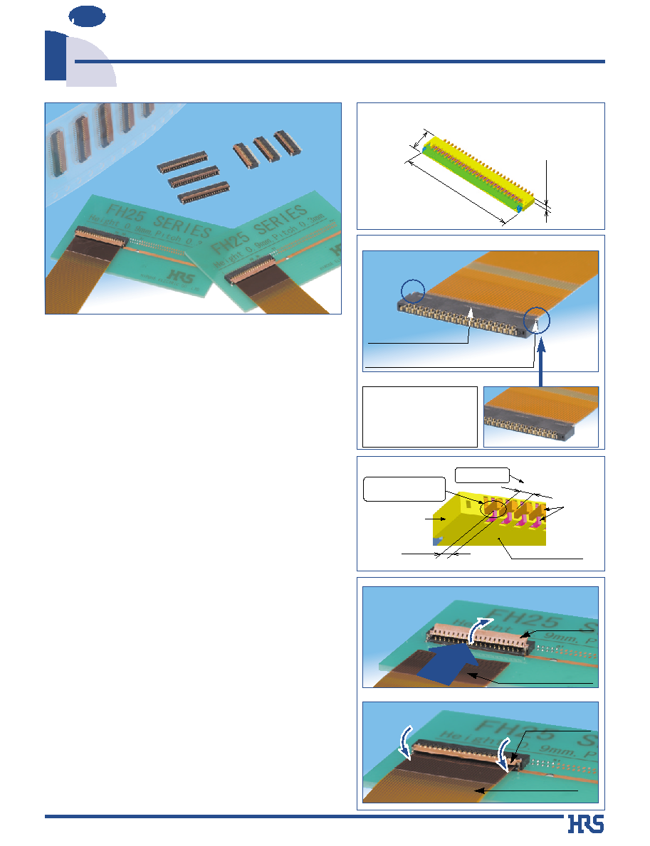
0.3 mm Contact Pitch, 0.9 mm above the board, Flexible Printed Circuit ZIF Connectors.
FH 25 Series
NEW
NEW
2004.6
s
Features
1. Extremely light weight
The largest version, with all contacts loaded, weights
only 0.11gramms.
2. Conductive traces on the PCB can run
under the connector
No exposed contacts on the bottom of the connector.
3. High density together with reliable solderability on the board
Staggered contact points and the leads plus the nickel
barriers assure sufficient distance to prevents solder
bridging.
4. Easy FPC insertion and reliable electrical connection
Proven Flip LockÆ actuator allows easy insertion of FPC.
Tactile sensation when fully closed confirms complete
electrical and mechanical connection.
5. Accepts standard thickness FPC
0.2 mm thick standard Flexible Printed Circuit board can
be used. This is the only ultra-low profile ZIF connector
allowing the use of standard FPC.
6. Board placement with automatic equipment
Flat top surface and packaging on the tape-and-reel
allows use of vacuum nozzles.
Standard reel contains 5,000 connectors.
s
Applications
Mobile phones, PDA's, digital cameras, digital video
cameras, LCD connections, plasma displays (PDP), camera
modules and other compact devices requiring Flexible
Printed Circuit connections using high reliability ultra-small
profile connectors.
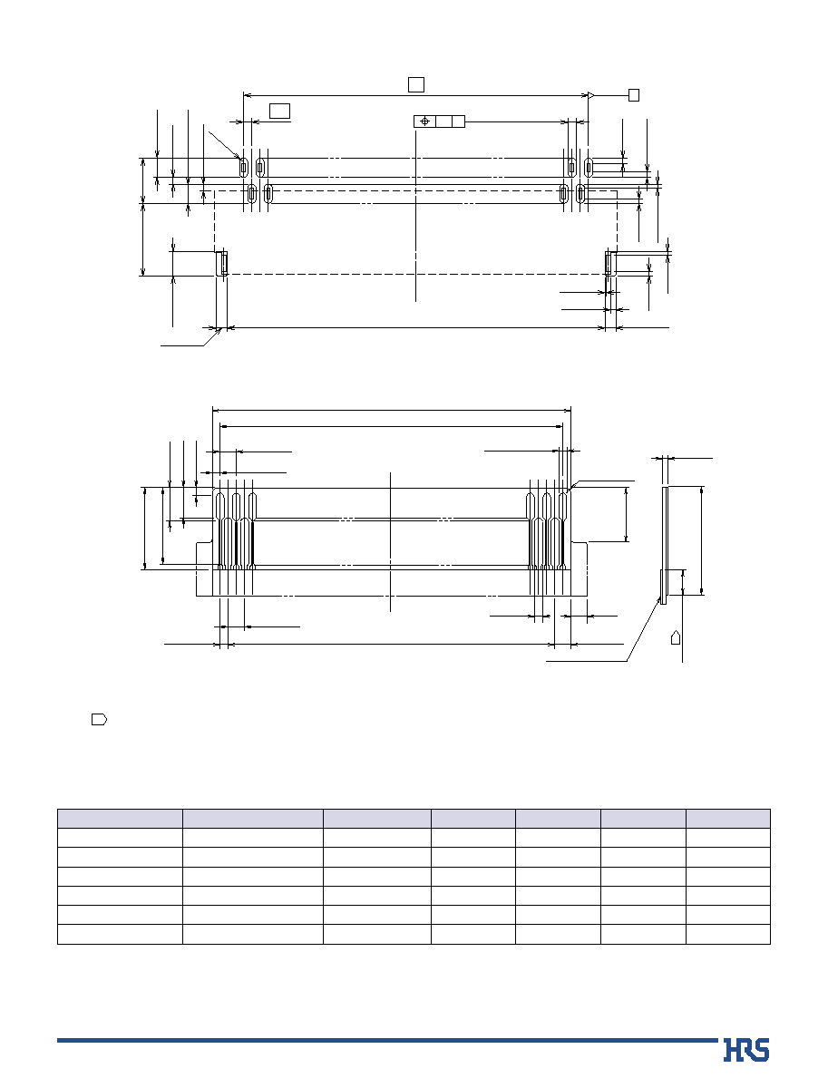
0.9mm
3.45mm
17.1mm
(51pos. type)
0.3mm
Solid bottom surface
0.6mm
Insulator body
Contacts
Mounting pitch
Nickel barrier prevents
solder bridges
Actuator open
FPC insertion direction
Actuator closed
FPC fully inserted
No exposed contacts
Metal fittings do not protrude outside of the connector body
Absence of protrusions on each
side of connector allows closer
side-by-side mounting of the
connectors or closer component
placement in miniaturized devices.
FPC
2
Item
Specification
Conditions
s
Materials
s
Ordering information
Part
Insulator
Contacts
Metal fittings
LCP
LCP
Phosphor bronze
Phosphor bronze
Color: Black
Color: Dark brown
Gold plated
Tin plated(No-lead)
UL94V-0
---------------
---------------
Material
Finish
Remarks
s
Product Specifications
Rating
Rated current 0.15 A DC
Rated voltage 30 V AC
Operating temperature range
-55Á to +85Á (Note 1)
Operating humidity range
Relative humidity 90% max. (No condensation)
Storage temperature range
-10Á to +50Á (Note 2)
Storage humidity range
Relative humidity 90% max.
Recommended FPC
Thickness: = 0.2±0.03mm thick, gold plated connecting traces
Note 1: Includes temperature rise caused by current flow.
Note 2: The term "storage" refers to products stored for long period of time prior to mounting and use. Operating Temperature Range and
Humidity range covers non- conducting condition of installed connectors in storage, shipment or during transportation.
50 M ohms min.
No flashover or insulation breakdown.
100 m ohms max.
* Including FPC conductor resistance
Contact resistance: 100 m ohms max.
No damage, cracks, or parts dislocation.
No electrical discontinuity of 1 µs or more.
Contact resistance: 100 m ohms max.
No damage, cracks, or parts dislocation.
No electrical discontinuity of 1 µs. min.
Contact resistance: 100 m ohms max.
No damage, cracks, or parts dislocation.
Contact resistance: 100 m ohms max.
Insulation resistance: 50 M ohms min.
No affect on appearance or performance.
Contact resistance: 100 m ohms max.
Insulation resistance: 50 M ohms min.
No damage, cracks, or parts looseness.
No deformation of components affecting performance.
100 V DC
90 V AC /one minute
1 mA
10 cycles
Frequency: 10 to 55 Hz,
single amplitude of 0.75 mm,
10 cycles,3 axis.
Acceleration of 981 m/s
2
,
6 ms duration, sine half-wave waveform,
3 cycles,3 axis.
96 hours at temperature of 40Á and humidity of 90% to 95%.
Temperature: -55
Á
/
+15
Á
to +35
Á
/
+85
Á
/
+15
Á
to +35
Á
Time: 30
/
2 to 3
/
30
/
2 to 3 (Minutes)
5 cycles
Reflow: At the recommended temperature profile
Manual soldering: 350Á±5Á for 5 seconds
1. Insulation resistance
2. Withstanding voltage
3. Contact resistance
4. Durability
(insertion/ withdrawal)
5. Vibration
6. Shock
7. Humidity
(Steady state)
8. Temperature cycle
9. Resistance to
soldering heat
-
-
-
(05)
SH
0.3
51S
FH25
1
2
3
4
5
Series name: FH25
No. of contacts
Number of contacts: 21, 27, 33, 39, 45, 51
Contact pitch: 0.3 mm
Terminal type
SH: SMT horizontal mounting type
Plating specifications
(05): Gold, selective flash plated
1
4
5
2
3
3
B
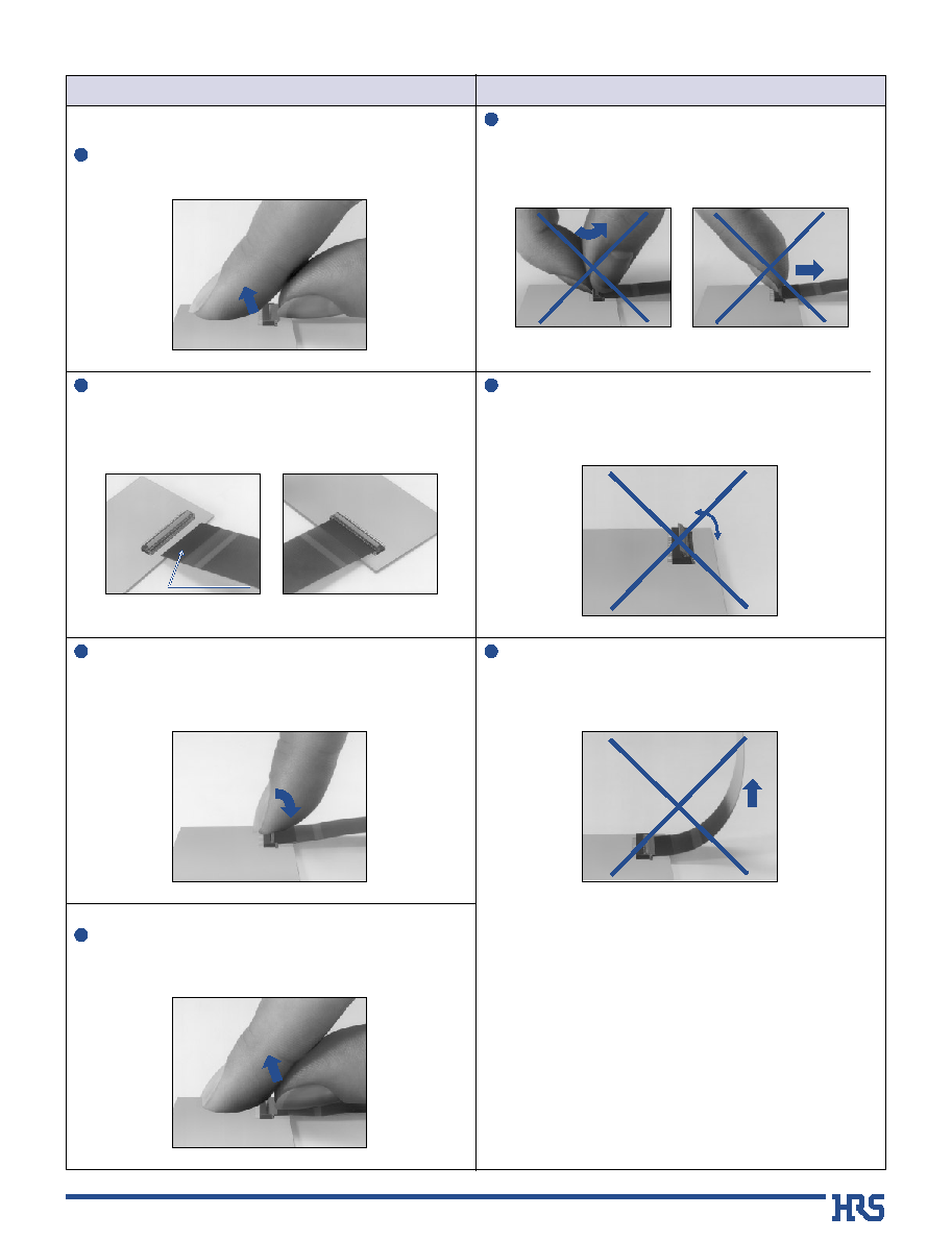
Operation and Precautions
Operation
Precautions
Lift up the actuator. Use thumb or index finger.
1.FPC insertion procedure. Connector installed on
the board.
1
Do not apply excessive force or use any type of tool to operate the
actuator.
1
Lift up the actuator.
Carefully withdraw the FPC.
2.FPC removal
1
3
Rotate down the actuator until firmly closed. It is critical that the
inserted FPC is not moved and remains fully inserted.
2
The connector will assure reliable performance when the actuator is
open to 130∞maximum. Do not exceed this angle, as this may cause
permanent damage to the connector.
130∞
3
Exercise caution when applying upward force to the connected FPC.
FPC conductor surface on opposite side.
Fully insert the FPC in the connector parallel to mounting surface, with
the exposed conductive traces facing down.
2
FPC conductor
surface
(Bottom side)
4
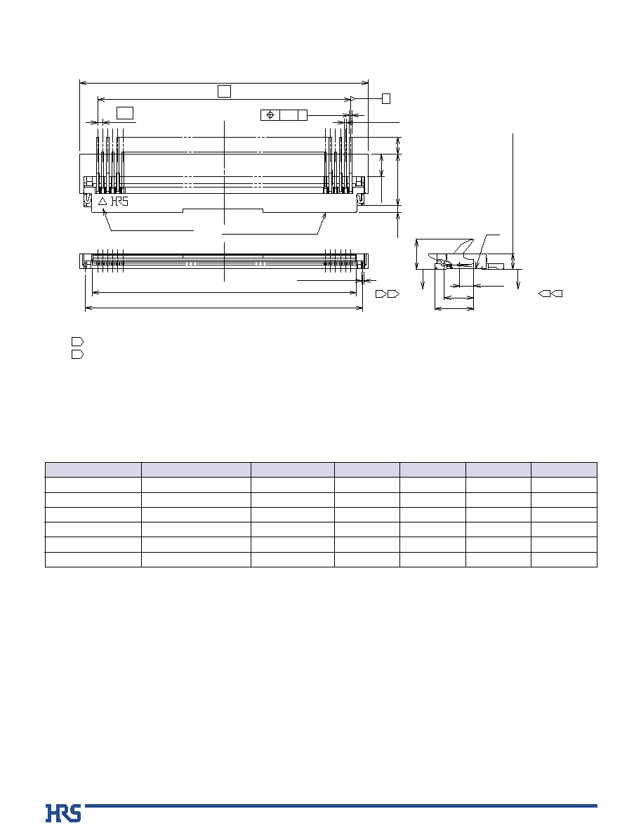
Notes
The coplanarity of each terminal lead is within 0.1.
The contact terminal lead position indicates the dimension from the E surface, the bottom surface of the insulator body.
Slight variations in color of the plastic compounds do not affect form, fit or function of the connector.
1
2
3
Number of contacts
0
0
0.1MAX.
0.1MAX.
0.15 G
B
A
(0.15)
A * *
0.3
(C: FPC insertion slot dimension)
D
1.0
3.05
Polarizing mark indicator
Number of contacts indicator
(1.35)
(0.15)
(0.4)
(0.12)
0.9(Including contact terminal leads)
(1.8)
2.3
E
(0.85)
(1.75)
1
2
2
1
G
s
Specifications
Unit: mm
Embossed tape reel packaging (5,000 pieces/reel).
Order by number of reels.
Part Number
FH25-21S-0.3SH(05)
FH25-27S-0.3SH(05)
FH25-33S-0.3SH(05)
FH25-39S-0.3SH(05)
FH25-45S-0.3SH(05)
FH25-51S-0.3SH(05)
CL586-1204-3-05
CL586-1205-6-05
CL586-1207-1-05
CL586-1208-4-05
CL586-1209-7-05
CL586-1200-2-05
21
27
33
39
45
51
8.1
9.9
11.7
13.5
15.3
17.1
6.0
7.8
9.6
11.4
13.2
15.0
6.64
8.44
10.24
12.04
13.84
15.64
7.45
9.25
11.05
12.85
14.65
16.45
CL No.
Number of Contacts
A
B
C
D
5
0.25±0.05(Metal mask)
Recommended metal mask thickness:
t = 0.1 mm
Number of contacts
0.1 H
H
0.7±0.03
(0.05)
(0.2)
A
0.3
0.3±0.05 (Land)
FULL R
0.9±0.03
0.4±0.03
0.4±0.03
(0.15)
(0.15)
B±0.05
1.65±0.03
0.7±0.03
(0.25)
2.65±0.05
(0.2)
(0.2)
(0.25)
(0.15)
(0.15)
B
Recommended PCB mounting pattern and metal mask dimensions
Covering film layer
2.8 MIN(Area with removed covering film layer)
Stiffener
2.8
0.2±0.03
C±0.05
A±0.03
D±0.03
0.3±0.07
0.6±0.02
0.3
+0.04
- 0.03
0.3
+0.04
- 0.03
2-R0.2 MAX
0.6±0.02
0.3±0.02
0.6±0.07
(2.3)
(0.6)
1.1±0.15
1.2±0.15
0.3±0.15
0.5MIN
2
B
Recommended FPC Dimensions
Polyamide and thermally hardening adhesive is recommended as the stiffener materials.
Overlap between covering film layer and stiffener is 0.5mm min.
1
2
Unit: mm
Embossed tape reel packaging (5,000 pieces/reel).
Order by number of reels.
Part Number
FH25-21S-0.3SH(05)
FH25-27S-0.3SH(05)
FH25-33S-0.3SH(05)
FH25-39S-0.3SH(05)
FH25-45S-0.3SH(05)
FH25-51S-0.3SH(05)
CL586-1204-3-05
CL586-1205-6-05
CL586-1207-1-05
CL586-1208-4-05
CL586-1209-7-05
CL586-1200-2-05
21
27
33
39
45
51
6.0
7.8
9.6
11.4
13.2
15.0
7.2
9
.0
10.8
12.6
14.4
16.2
6.6
8.4
10.2
12.0
13.8
15.6
5.4
7.2
9.0
10.8
12.6
14.4
CL No.
Number of Contacts
A
B
C
D
6
A±0.3
(0.3)
B±0.1
Unreeling direction
(C)
1.75±0.1
(1.7)
8±0.1
2±0.15
4±0.1
ÿ1.5
+0.1
0
(5.25)
(1.35)
(3.75)
B
Packaging Specification
Unit: mm
Part Number
FH25-21S-0.3SH(05)
FH25-27S-0.3SH(05)
FH25-33S-0.3SH(05)
FH25-39S-0.3SH(05)
FH25-45S-0.3SH(05)
FH25-51S-0.3SH(05)
CL586-1204-3-05
CL586-1205-6-05
CL586-1207-1-05
CL586-1208-4-05
CL586-1209-7-05
CL586-1200-2-05
21
27
33
39
45
51
16
24
24
24
24
24
7.5
11.5
11.5
11.5
11.5
11.5
8.4
10.2
12.0
13.8
15.6
17.4
16.5
24.5
24.5
24.5
24.5
24.5
CL No.
Number of Contacts
A
B
C
D
q
Reel Dimensions
5,000 pieces per reel.
q
Embossed Carrier Tape Dimensions
Flat surface for placement
with automatic equipment
Embossed carrier tape
Top cover tape
(ÿ80)
(ÿ380)
(2)
(D)
Blank portion
(10 pockets min.)
Blank portion
(10 pockets min.)
End portion
Lead portion (400mm min.)
Mounting portion
ÿ13±0.5
7
B
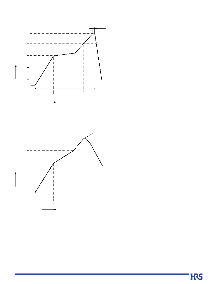
Recommended Temperature Profile
HRS test conditions
Solder method
:Reflow, IR/hot air
(Nihon Den-netsu Co., Ltd.'s Part Number:
SENSBY NR-2)
Environment
:Room air
Solder composition :Paste, 63%Sn/37%Pb
(Senju Metal Industry, Co., Ltd.'s Part Number:
OZ63-201C-50-9)
Test board
:Glass epoxy 70mm80mm1.6mm thick
Land dimensions:
0.3mm0.65mm,0.3mm0.8mm
Metal mask
:0.230.550.1mm thick,
0.230.650.1mm thick
This temperature profile is based on the above conditions.
In individual applications the actual temperature may vary,
depending on solder paste type, volume/thickness and board
size/thickness. Consult your solder paste and equipment
manufacturer for specific recommendations.
Start
Preheating
Soldering
Temperature
Á)
Time (Seconds)
60
25Á
(60sec.)
20 sec. to 30 sec.
(30sec.)
60 sec. to 90 sec.
0
50
100
150
150Á
160Á
240Á
200Á
5 sec. max.
200
250
120
q
Using Typical Solder Paste
HRS test condition
Solder method
:Reflow, IR/hot air
(Nihon Den-netsu Co., Ltd.'s Part Number:
SENSBY NR-2)
Environment
:Room air
Solder composition :Paste, 96.5%Sn/3.0%Ag/0.5%Cu
(Senju Metal Industry, Co., Ltd.'s Part Number:
M705-221CM5-42-10.5)
Test board
:Glass epoxy 70mm80mm1.6mm thick
Land dimensions:
0.3mm0.65mm, 0.3mm0.8mm
Metal mask
:0.230.550.1mm thick,
0.230.650.1mm thick
The temperature profiles are based on the above conditions.
In individual applications the actual temperature may vary,
depending on solder paste type, volume/thickness and board
size/thickness. Consult your solder paste and equipment
manufacturer for specific recommendations.
MAX 250Á
60
25Á
(60sec.)
(60sec.)
60 sec. to 120 sec.
0
50
100
150
150Á
200Á
230Á
200
250
120
Start
Preheating
Soldering
Temperature
Á)
Time (Seconds)
q
Using Lead-free Solder Paste

8
B
FH25 Series FPC Construction (Recommended)
1. Using Single-sided FPC
Name
Covering film layer
Cover adhesive
Surface treatment
Copper foil
Base adhesive
Base film
Reinforcement material adhesive
Stiffener
Polyamide 1 mil thick.
1µm to 5µm nickel underplated
0.2µm gold plated
Cu
1oz
Polyamide 1 mil thick
Polyamide 3 mil thick
Total
25
25
(3)
35
25
25
30
75
193
Material
Thickness (µm)
2. Using Double-sided FPC
3. Precautions
Name
Covering film layer
Cover adhesive
Surface treatment
Through-hole copper
Copper foil
Base adhesive
Base film
Base adhesive
Copper foil
Cover adhesive
Covering layer film
Reinforcement material adhesive
Stiffener
Polyamide 1 mil thick
1µm to 5µm nickel underplated
0.2µm gold plated
Cu
Cu
1/2oz
Polyamide 1 mil thick
Cu
1/2oz
Polyamide 1 mil thick
Polyamide 1 mil thick
Total
25
25
(3)
15
18
18
25
18
18
25
25
25
25
197
Material
Thickness (µm)
Note: Recommended specification for FPC 0.2 ± 0.03 mm thick.
To prevent release of the lock due to FPC bending, use of the FPC with copper foil on rear side is NOT RECOMMENDED.
Rear side
The contents of this catalog are current as of date of publication. Contents are subject to change without notice for the purpose of improvements.
5-23,OSAKI 5-CHOME,SHINAGAWA-KU,TOKYO 141-8587,JAPAN
PHONE: 81-3-3491-9741, FAX: 81-3-3493-2933
http://www.hirose.com
http://www.hirose-connectors.com
Æ