A189
Stacking Height 5 to 11mm Half Pitch Connector
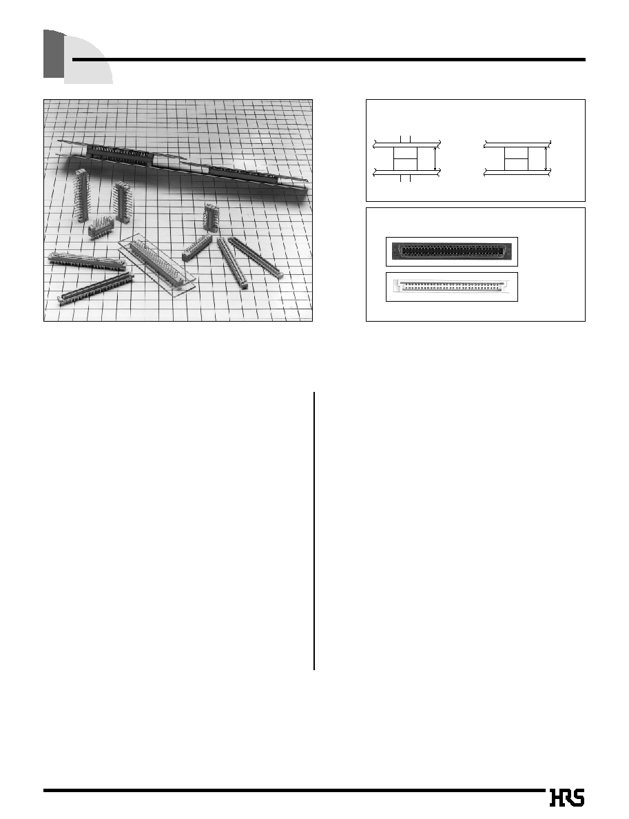
FX4 Series
5 to 11mm
DIP type
6 to 11mm
SMT type
Stacking Height Flexible
The mounting area 70% reduced, compared with
conventional product (FX2 series)
FX2 series
FX4 series
(Compared with 60 contacts)
s
Features
The FX4 series is a miniature board to board connectors, where the stacking height can be set at the 1mm interval.
According to the mounting method, you can select the product from the through hole type and SMT type.
s
Applications
Computers, peripheral equipments, business equipments, etc.
q
Through hole Type
1. Small and Light
The mounting space and weight is reduced about 30%,
compared to the conventional product (HRS FX2 series),
respectively, and the mounting area about 70% reduced,
compared to the conventional one.
2. Stacking Height 5 to 11mm
The board to board stacking height can be set per 1mm
from 5mm up to 11mm.
3. Flux Swell Prevention
When solder is dipped, the flux swell from the board rear
side is completely prevented.
4. Mis-insertion Prevention and Low
Insertion/Extraction Force Mechanism
The connection area is designed to completely prevent the
mis-insertion.
Moreover, the low insertion/extraction mechanism is
adopted.
q
SMT Type
1. Small and Light
The mounting space and weight is reduced about 40%,
compared with the conventional product (HRS FX2 series),
and the mounting area is reduced 80%, compared to the
conventional one.
2. Stacking Height 6 to 11mm
The board to board stacking height can be set per 1mm
from 6mm up to 11mm. In addition, the height can be also
set in combination with the through hole type.
3. Mis-insertion Prevention and Low
Insertion/Extraction Structure
The connection area is designed to completely prevent the
mis-insertion.
Moreover, the low insertion/extraction force mechanism is
adopted.
4. Positioning Boss Selectable
According to the mounting condition, it is selected whether
or not the boss is required. Regarding the boss attached
type, the boss eccentric position can stabilize the mounting
direction.

A190
s
Product Specifications
Rating
Current rating 0.5A
Operating Temperature Range -55
�
to +85
�
(Note 1)
Storage Temperature Range -10
� to
+60
�
(Note 2)
Voltage rating 125V AC
Operating Humidity Range 40
%
to 80
%
Storage Humidity Range 40
% to
70
%
Item
Specification
Condition
1. Insulation Resistance
100M
ohms
min.
Measured at 250V PC
2. Withstanding Voltage
No flashover or insulation breakdown.
300V AC for 1 minute
3. Resistance
45m
ohms
max.
100mA
4. Vibration
No electrical discontinuity of 1�s or more
Frequency: 10 to 55 Hz, single amplitude of 0.75 mm, 2 hours in each of the 3 directions.
5.
Humidity (Steady state)
Contact resistance: 55m
ohms
max. Insulation resistance: 100M
ohms
min.
96 hours at temperature of 40� and humidity of 90% to 95%
6. Temperature Cycle
Contact resistance : 55m
ohms
max.
(-55
�
: 30 minutes 15
to
35
�
: 2
to
3 minutes
Insulation resistance : 100M
ohms
min.
(-
85
�
: 30 minutes 15
to
35
�
: 2
to
3minutes) 5 cycles
7. Durability (Mating/un-mating) Contact resistance : 55m
ohms
max.
300 cycles
8. Resistance to Soldering heat
No deformation of components affecting performance. Reflow: At the recommended temperature profile
Manual soldering: 300� for 3 seconds
Note 1: Includes temperature rise caused by current flow.
Note 2: The term "storage" refers to products stored for long period of time prior to mounting and use. Operating Temperature Range and
Humidity range covers non conducting condition of installed connectors in storage, shipment or during transportation.
Note : The black dots on the insulater will not affect performance.
s
Material
Part
Material
Finish
Remarks
Insulator
Polyamide
Beige
UL94V-0
Receptacle Contact
Selective gold plated
________
Header Contact
Phosphor bronze
Selective gold plated
________
s
Ordering Information
FX 4C 1 - 80 P - 1.27 DSA L
q
w
r
e
t
y
u
i
t
Connector Type
P : Header
S : Receptacle
y
Contact Pitch : 1.27mm
u
Contact type DSA : Straight
i
L: Board prefixed pin
q
Series Name : FX
w
Series No.
: 4C
e
Product Height Variable:None: Standard 1: +1mm
2: +2mm
3: +3mm
r
Number of Contacts: 20, 32, 40, 52, 60, 68, 80
q
Dip Type
FX 4A H - 80 P - 1.27 SV
q
w
r
e
t
y
u
r
Number of Contacts : 20, 32, 40, 52, 60, 68, 80
t
Connector Type
P : Header
S : Receptacle
y
Contact Pitch : 1.27mm
u
Contact type SV : Vertical type
q
Series Name : FX
w
Series No.
: 4A : With boss
4B : Without boss
e
Product Height Variable
H : +0.5mm
1 : +1mm
e
(Ratio to dip type standard product)
2 : +2mm
3 : +3mm
q
SMT Type

A191
FX4AH-
*
P
FX4AH-
*
S
FX4BH-
*
P
FX4BH-
*
S
B
Application Pattern and Stacking Height Combination
q
Through hole Type
q
SMT Type
q
Through hole Type and SMT Type
Receptacle
Header
FX4C -
*
S
FX4C2-
*
S
FX4C3-
*
S
(Catalog page A195) (Catalog page A196) (Catalog page A197)
5
7
8
6
8
9
8
10
11
FX4C -
*
P
(Catalog page A192)
FX4C1-
*
P
(Catalog page A193)
FX4C3-
*
P
(Catalog page A194)
Unit: mm
Receptacle
Header
FX4A1-
*
S
FX4A2-
*
S
FX4A3-
*
S
(Catalog page A202) (Catalog page A203) (Catalog page A204)
FX4B1-
*
S
FX4B2-
*
S
FX4B3-
*
S
(Catalog page A202) (Catalog page A203) (Catalog page A204)
7
8
9
9
10
11
FX4A1-
*
P
(Catalog page A199)
FX4B1-
*
P
(Catalog page A199)
FX4A3-
*
P
(Catalog page A200)
FX4B3-
*
P
(Catalog page A200)
Unit:mm
Receptacle
Header
FX4A1-
*
S
FX4A2-
*
S
FX4A3-
*
S
(Catalog page A202)
(Catalog page A203) (Catalog page A204)
FX4B1-
*
S
FX4B2-
*
S
FX4B3-
*
S
(Catalog page A202)
(Catalog page A203) (Catalog page A204)
6
7
8
7
8
9
9
10
11
FX4C -
*
P
(Catalog page A192)
FX4C1-
*
P
(Catalog page A193)
FX4C3-
*
P
(Catalog page A194)
Unit:mm
Receptacle
Header
FX4A1-
*
P
FX4A3-
*
P
(Catalog page A199) (Catalog page A200)
FX4B1-
*
P
FX4B3-
*
P
(Catalog page A199) (Catalog page A203)
6
8
8
10
9
11
FX4C -
*
S
(Catalog page A195)
FX4C2-
*
S
(Catalog page A196)
FX4C3-
*
S
(Catalog page A197)
� The stacking height 6mm follows the diagonal
diagram as shown below.
� The stacking height 7mm to 11mm follows the table
as shown below.
The above stacking height doesn't include the solder paste thickness.
Thus, please consider that the stacking height after the mounting process will be slightly higher than the conventional height.

A192
s
Header (Through hole Type)-Stacking Height: Standard type
B
PCB mounting pattern
Part Number
CL No.
Number of Contacts
A
B
C
D
FX4C-20P-1.27DSA
574-0001-0
________
FX4C-20P-1.27DSAL
574-0051-9
20
21.87
14.58
11.43
20.32
FX4C-32P-1.27DSA
574-0002-3
________
FX4C-32P-1.27DSAL
574-0052-1
32
29.49
22.2
19.05
27.94
FX4C-40P-1.27DSA
574-0003-6
________
FX4C-40P-1.27DSAL
574-0053-4
40
34.57
27.28
24.13
33.02
FX4C-52P-1.27DSA
574-0004-9
________
FX4C-52P-1.27DSAL
574-0054-7
52
42.19
34.9
31.75
40.64
FX4C-60P-1.27DSA
574-0005-1
________
FX4C-60P-1.27DSAL
574-0055-0
60
47.27
39.98
36.83
45.72
FX4C-68P-1.27DSA
574-0006-4
________
FX4C-68P-1.27DSAL
574-0056-2
68
52.35
45.06
41.91
50.8
FX4C-80P-1.27DSA
574-0007-7
________
FX4C-80P-1.27DSAL
574-0057-5
80
59.97
52.68
49.53
58.42
Unit: mm

A193
s
Header (Through hole Type)-Stacking Height: Standard+1mm type
B
PCB mounting pattern
Part Number
CL No.
Number of Contacts
A
B
C
D
FX4C1-20P-1.27DSA
574-0011-4
________
FX4C1-20P-1.27DSAL
574-0061-2
20
21.87
14.58
11.43
20.32
FX4C1-32P-1.27DSA
574-0012-7
________
FX4C1-32P-1.27DSAL
574-0062-5
32
29.49
22.2
19.05
27.94
FX4C1-40P-1.27DSA
574-0013-0
________
FX4C1-40P-1.27DSAL
574-0063-8
40
34.57
27.28
24.13
33.02
FX4C1-52P-1.27DSA
574-0014-2
________
FX4C1-52P-1.27DSAL
574-0064-0
52
42.19
34.9
31.75
40.64
FX4C1-60P-1.27DSA
574-0015-5
________
FX4C1-60P-1.27DSAL
574-0065-3
60
47.27
39.98
36.83
45.72
FX4C1-68P-1.27DSA
574-0016-8
________
FX4C1-68P-1.27DSAL
574-0066-6
68
52.35
45.06
41.91
50.8
FX4C1-80P-1.27DSA
574-0017-0
________
FX4C1-80P-1.27DSAL
574-0067-9
80
59.97
52.68
49.53
58.42
Unit: mm