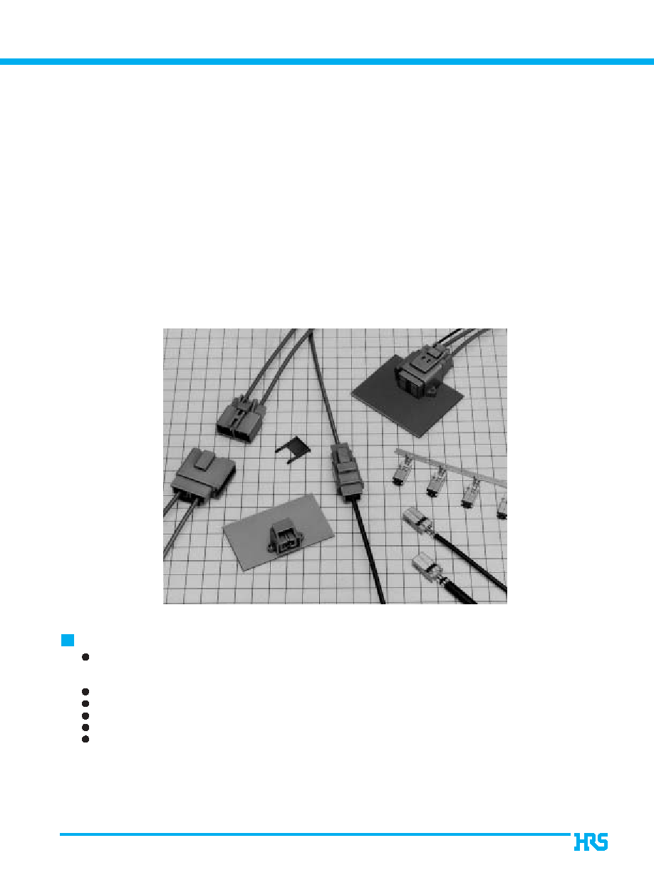
Coaxial cable connection of Antennas, Sensors, and Communication Trunk Lines
GT1 Series
-- Connectors for coaxial cables --
<
Several types and configurations: In-line, board mounted, combinations of
coaxial cable with signal/power. Multi-position.
>
2003.6
Features
Cost efficient termination
Highly efficient and reliable single motion crimp termination allows high volume production with semi-
automatic equipment.
Lock-release latching system
Shock / vibration resistant electrical connections
Verification of the full contact insertion
Excellent shielding effects.
Excellent High Frequency Performance
Refer to V.S.W.R. data on the following pages.
Termination of coaxial cables in automotive, medical and instrumentation applications
utilizes a single motion to crimp the center conductor, shield and outer Insulator.
2
B
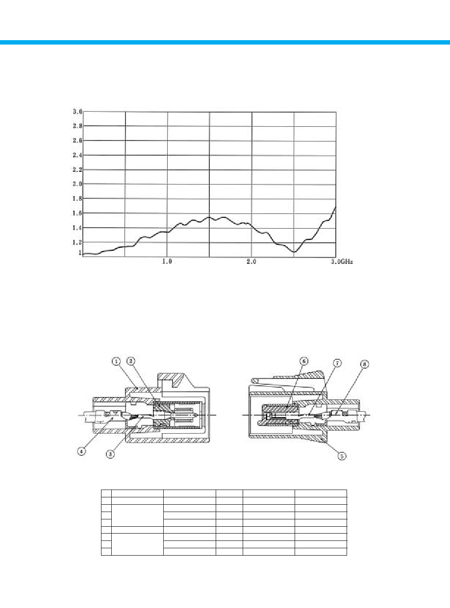
Diagram of GT1 In-line Type Structure
High Frequency Characteristics (V.S.W.R.)
Note: Data taken using fully assemblied and connected GT1-1S-HU and GT1-1P-DSA.
Part Number
Part
Number Used
Material
Finish
1
GT1-1P-HU
Housing
1
PA(UL94V-0
----
2
Insulator
1
PBT(UL94V-0
----
3
GT1-1P-2428/1.6C
Crimp terminal
1
Brass
Tin plating
4
Outer terminal
1
Brass
Tin plating
5
GT1-1S-HU
Housing
1
PA(UL94V-0
----
6
Insulator
1
PBT(UL94V-0
----
7
GT1-1S-2428/1.6C
Crimp terminal
1
Phosphor bronze
Tin plating
8
Outer terminal
1
Brass
Tin plating
B
Test Data (Using Semi-rigid Cable)
3
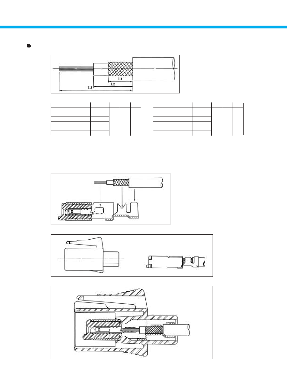
B
Termination sequence
Part Number
CL No.
L1
L2
L3
Part Number
CL No.
L1
L2
L3
GT1-1S-2428 / 1.6C
GT1-1P-2428 / 1.6C
GT1-1S-30 / 1.6C
GT1-1P-30 / 1.6C
GT1-1S-2022 / 2.9C
GT1-1P-2022 / 2.9C
3.8
751-0001-3
751-0002-6
751-0029-2
751-0030-1
751-0015-8
751-0014-5
4.9
6.8
11.3
6
10.5
GT1-1S-30 / 2.9C
GT1-1P-30 / 2.9C
GT1-1S-2428 / F5C
GT1-1P-2428 / F5C
GT1-1S-30 / F5C
GT1-1P-30 / F5C
4.9
6.8
11.3
Strip Length
1
Crimp the cable to the terminal.
2
Insert the terminal in the housing until is fully locked.
3
Completion
751-0032-7
751-0031-4
751-0033-0
751-0034-2
751-0037-0
751-0038-3
Coaxial Cable Terminal Finish Diagram
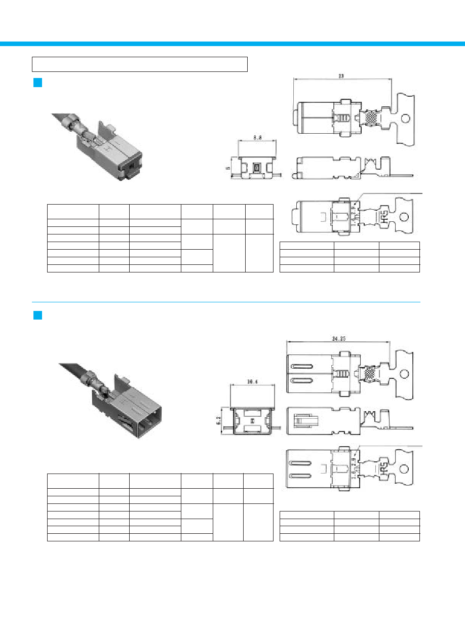
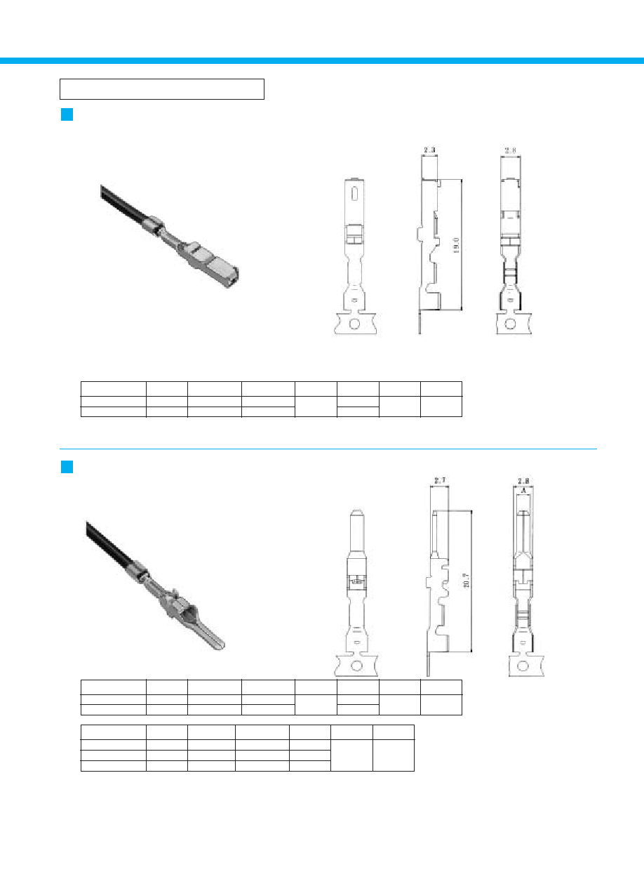
4
Terminals for coaxial shielded cable
Item
Material
Finish
Insulator
PBT
Color: Dark gray
Crimp terminal
Brass
Tin plating
Outer terminal
Brass
Tin plating
Note: Products marked with an asterisk (*) indicate polyethylene foam insulation.
Part Number
CL No.
GT1-1P-2428 / 1.6C
GT1-1P-30 / 1.6C
GT1-1P-2022 / 2.9C
GT1-1P-30 / 2.9C
GT1-1P-2428 / F5C
GT1-1P-30 / F5C
GT1-1P-2428 / F4C
751-0002-6
751-0030-1
751-0014-5
751-0031-4
751-0034-2
751-0038-3
751-0047-4
Inner Insulator
Diameter
Outer
Diameter
Packaging
1.5 to 2.0mm 2.6 to 3.4mm
0,
800
2.8 to 3.5mm
2.5 to 3.5mm
4.0mm
0,
600
4.6 to 5.0mm
Note: Products marked with an asterisk (*) indicate polyethylene foam insulation.
Part Number
0,
800
GT1-1S-2428 / 1.6C
GT1-1S-30 / 1.6C
GT1-1S-2022 / 2.9C
GT1-1S-30 / 2.9C
GT1-1S-2428 / F5C
GT1-1S-30 / F5C
GT1-1S-2428 / F4C
*
*
751-0001-3
751-0029-2
751-0015-8
751-0032-7
751-0033-0
751-0037-0
751-0046-1
#24 to 28 or equivalent
#30 or equivalent
#20 to 22 or equivalent
#30 or equivalent
#24 to 28 or equivalent
#30 or equivalent
#24 to 28 or equivalent
Conductor Size
(AWG)
CL No.
Inner Insulator
Diameter
1.5 to 2.0mm 2.6 to 3.4mm
4.6 to 5.0mm
2.8 to 3.5mm
2.5 to 3.5mm
4.0mm
Outer
Diameter
Packaging
1,200
Indication of
Conductor Size (AWG)
#24 to 28 or equivalent
#30 or equivalent
#20 to 22 or equivalent
#30 or equivalent
#24 to 28 or equivalent
#30 or equivalent
#24 to 28 or equivalent
Conductor Size
(AWG)
F Connector Terminals
M Connector Terminals
Indication of
Conductor Size (AWG)
*
*
Item
Material
Finish
Insulator
PBT
Color: Dark gray
Crimp terminal
Brass
Tin plating
Outer terminal
Brass
Tin plating
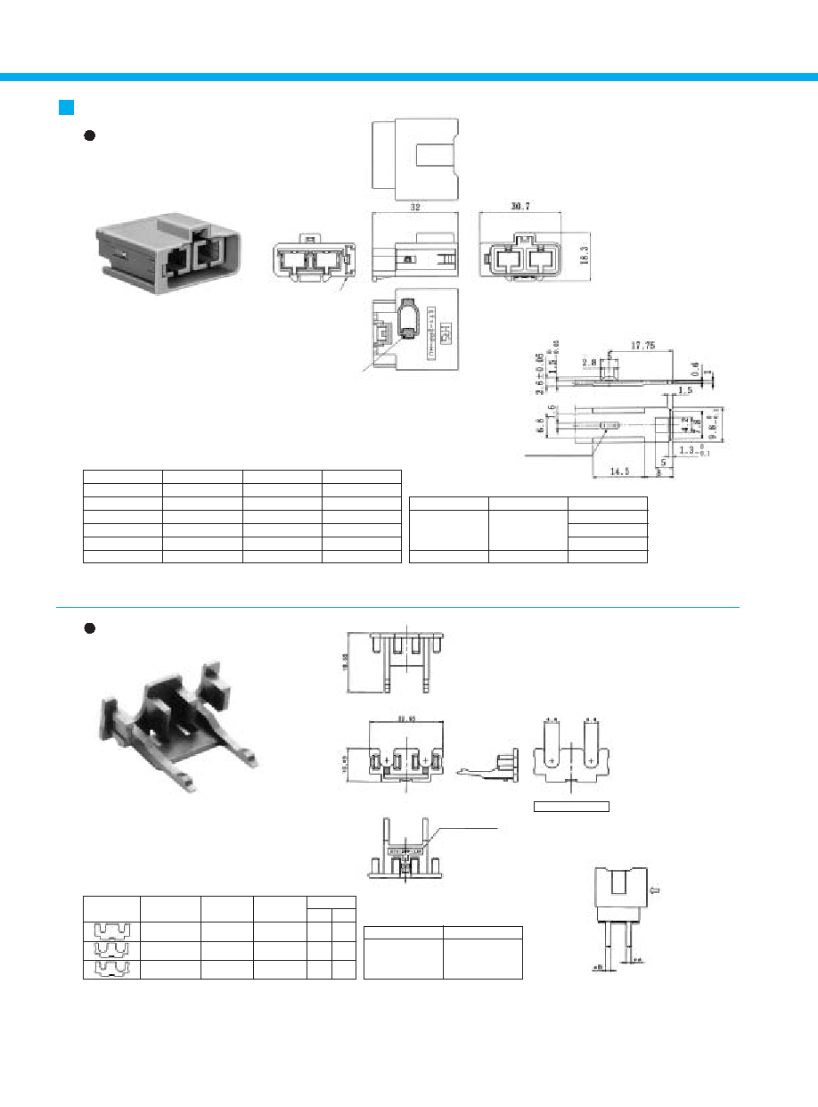
5
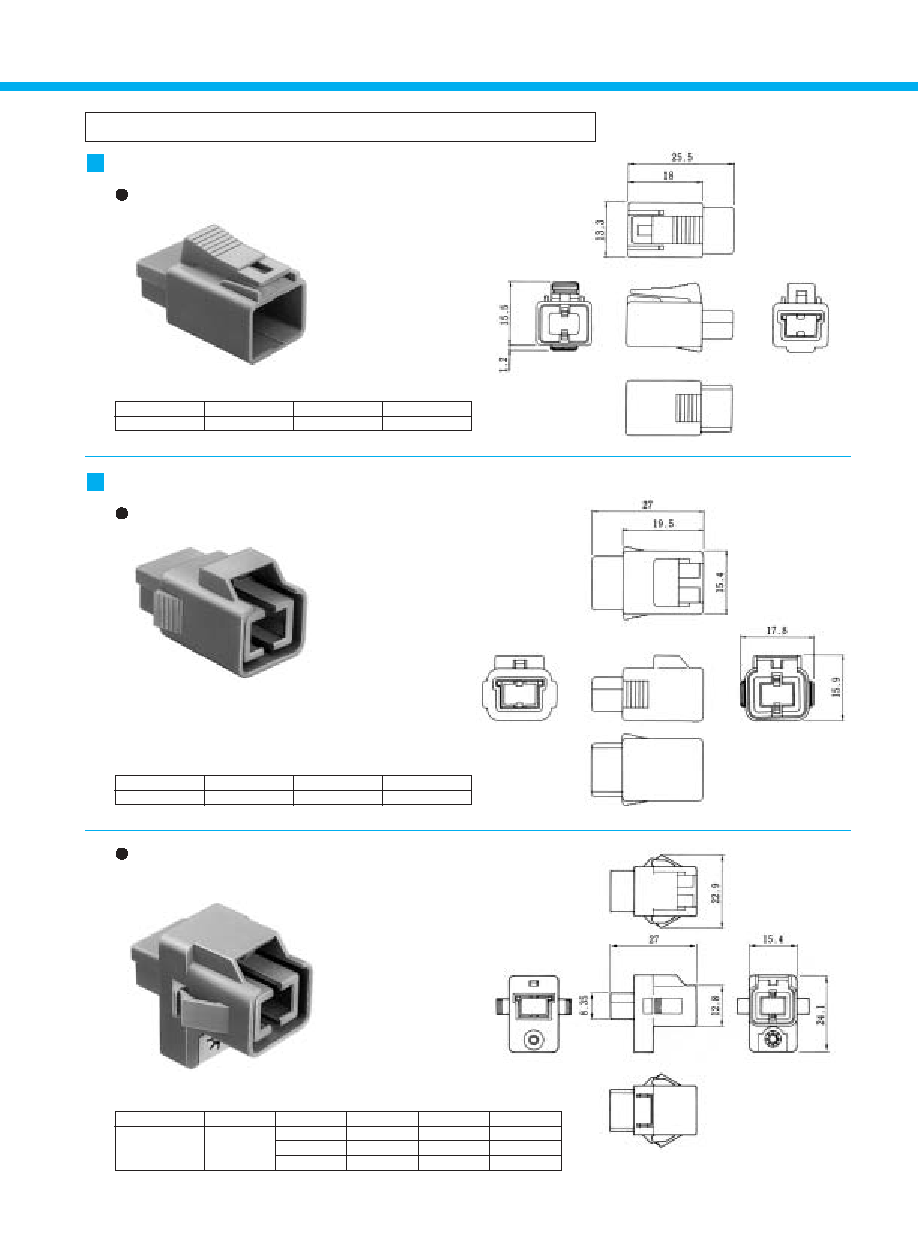
For Single-Conductor coaxial shielded cable
Part Number
CL No.
Item
Material
Finish
Color
Housing
PA
----
Light gray
GT1-1PP-HU
751-0007-0
Ground plate
Brass
Tin plating
----
Press fitting nut
Brass
Nickel
----
Part Number
CL No.
Material
Color
GT1-1S-HU
751-0003-9
PA
Light gray
Part Number
CL No.
Material
Color
GT1-1P-HU
751-0004-1
PA
Light gray
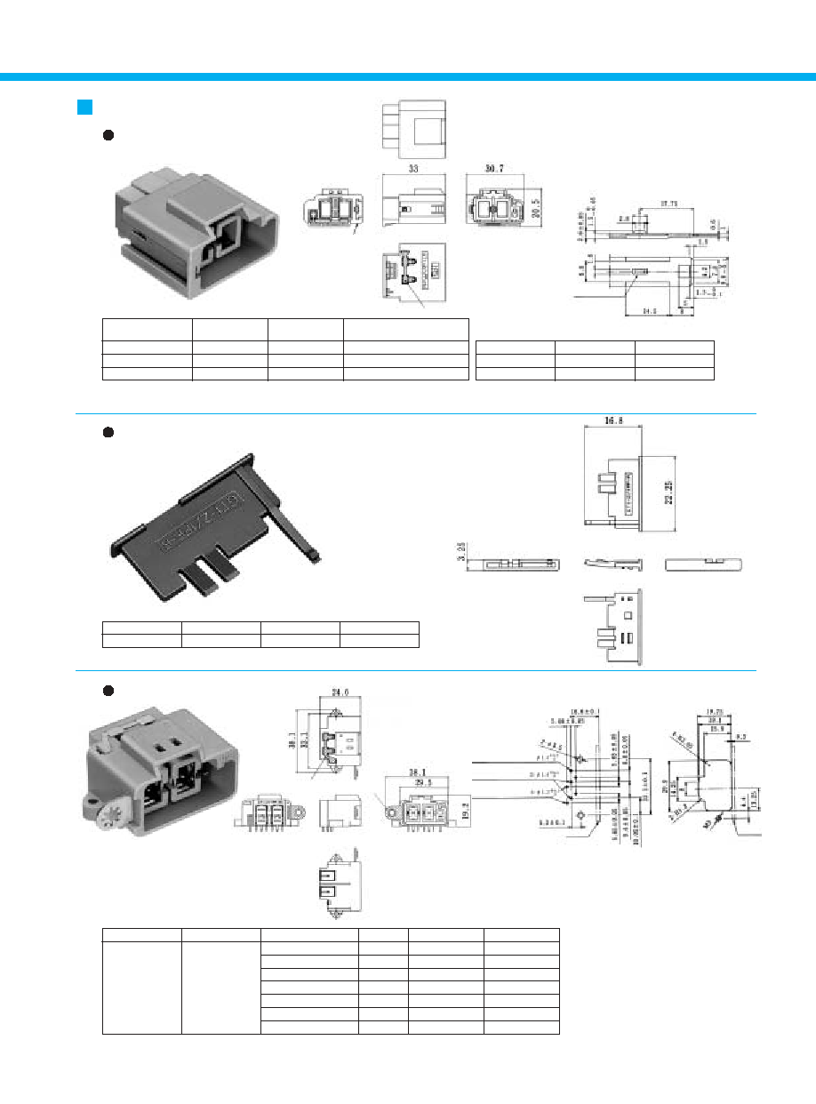
F Connectors
Housing
M Connectors
Housing
Panel Housing

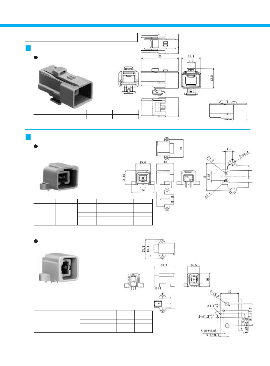
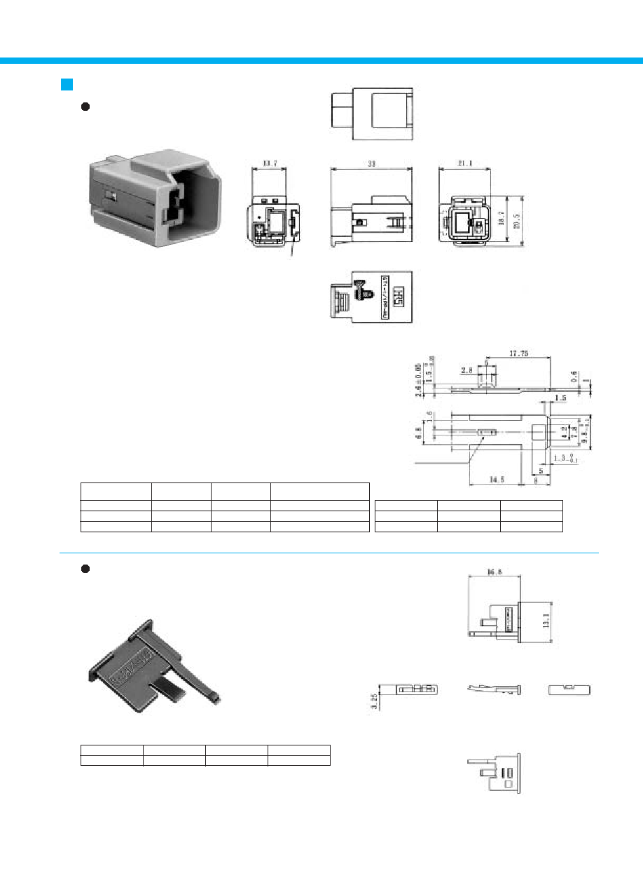
6
Part Number
CL No.
Item
Material
Finish
Color
Housing
PBT
----
Light gray
Insulator
PBT
----
Dark gray
GT1-1P-DS
751-0006-7
0.64X1.1 Terminal
Brass
Tin plating
----
Outer terminal
Brass
Tin plating
----
Ground terminal
Stainless
----
----
Use mounting screws of M3 with nominal diameter 3L-6 (for a panel thickness of 0.16mm)
Part Number
CL No.
Item
Material
Finish
Color
Housing
PBT
----
Light gray
Insulator
PBT
----
Dark gray
GT1-1P-DSA
751-0005-4
0.64X1.1 Terminal
Brass
Tin plating
----
Outer terminal
Brass
Tin plating
----
Use mounting screws of M3 with nominal diameter 3L-6 (for a panel thickness of 0.16mm)
B
Recommended Board Mounting Pattern
Printed Circuit Type (Right angle)
For outer conductor
For inner conductor
Printed Circuit Type (Straight Dip Type)
B
Recommended Board Mounting Pattern
For outer conductor
For inner conductor
7
Note: Mates only with GT1K-1P-DS and GT1K-1PA-DS.
* Refer to Page 14 for use of the GT1K-1P-HU retainer.
Note 1: Mates only with GT1K-1S-HU.
Note 2: Use mounting screws of M3 with nominal diameter 3L-6 (for a panel thickness of 0.16mm)
For Single-Conductor coaxial shielded cable
Part Number
CL No.
Material
Color
GT1K-1S-HU
751-0016-0
PBT
Light gray
B
Shown with inserted retainer
B
Recommended Board
Mounting Pattern
Part Number
CL No.
Item
Material
Finish
Color
Housing
PBT
----
Light gray
Insulator
PBT
----
Dark gray
GT1K-1P-DS
751-0017-3
0.64X1.1 Terminal
Brass
Tin plating
----
Outer terminal
Brass
Tin plating
----
Cover
Stainless
Nickel
----
Note 1: Mates only with GT1K-1S-HU.
Note 2: Use mounting screws of M3 with nominal diameter 3L-6 (for a panel thickness of 0.16mm)
Part Number
CL No.
Item
Material
Finish
Color
Housing
PBT
----
Light gray
Insulator
PBT
----
Dark gray
GT1K-1PA-DS
751-0035-5
0.64X1.1 Terminal
Brass
Tin plating
----
Outer terminal
Brass
Tin plating
----
F Connectors
Housing (Integrated retainer type)
For outer conductor
For inner conductor
M Connectors
Printed Circuit Board Type
(Right-angle Dip Top Lock Type)
Printed Circuit Board Type
(Right-angle Dip Side Lock Type)
B
Recommended Board
Mounting Pattern
For outer conductor
For inner conductor
Panel
8
B
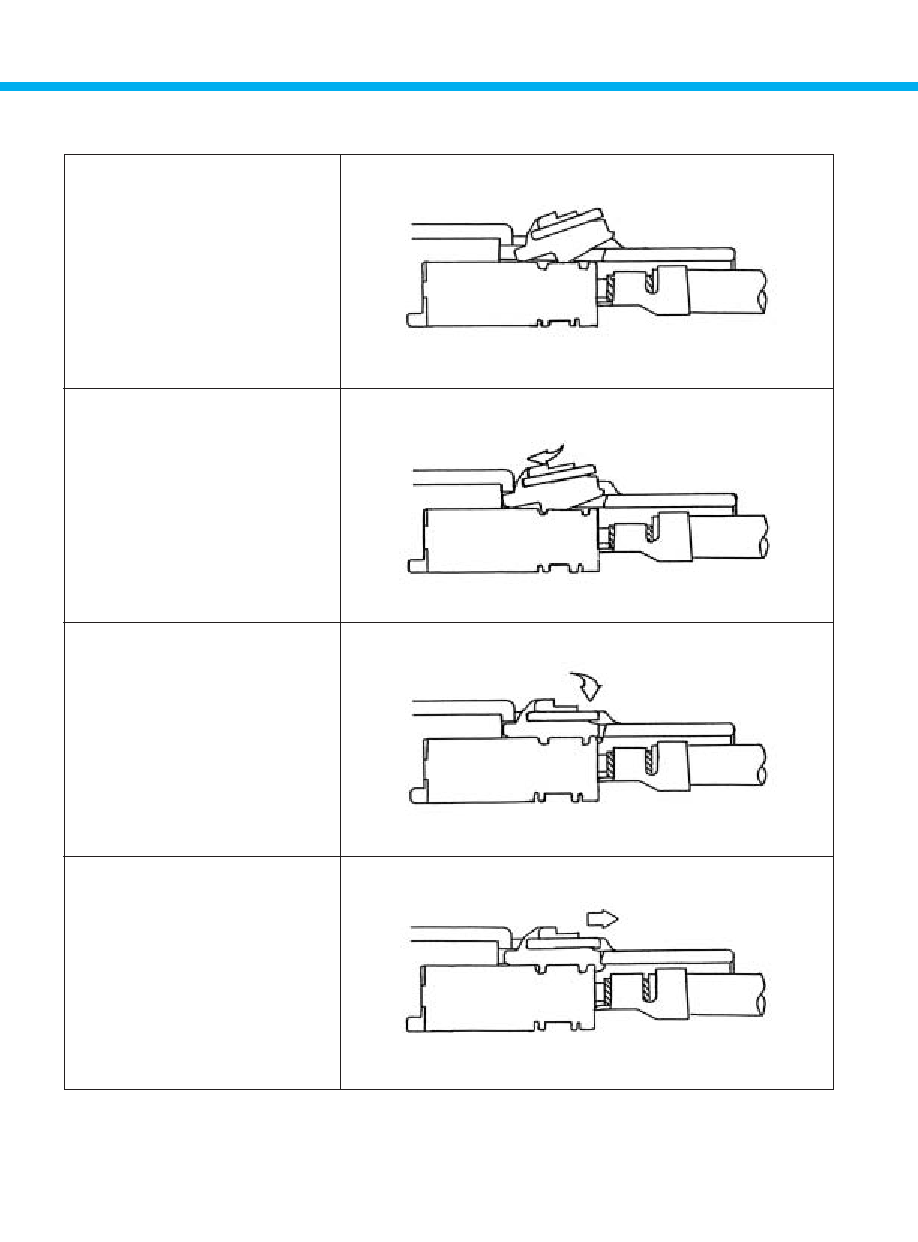
Method of Using the GT1K-1S Retainer
a. Insert so that the terminal
locking tab is inserted
between the top surface
of the terminal and the
housing.
b. Push in while changing
the angle of the retainer
until the front surface
comes to a stop.
c. Press the rear portion of
the retainer and snap it
into the locked position.
d. If locking is not complete,
press the rear portion of
the retainer again while
pulling it backward.
* Check that all locations are locked.
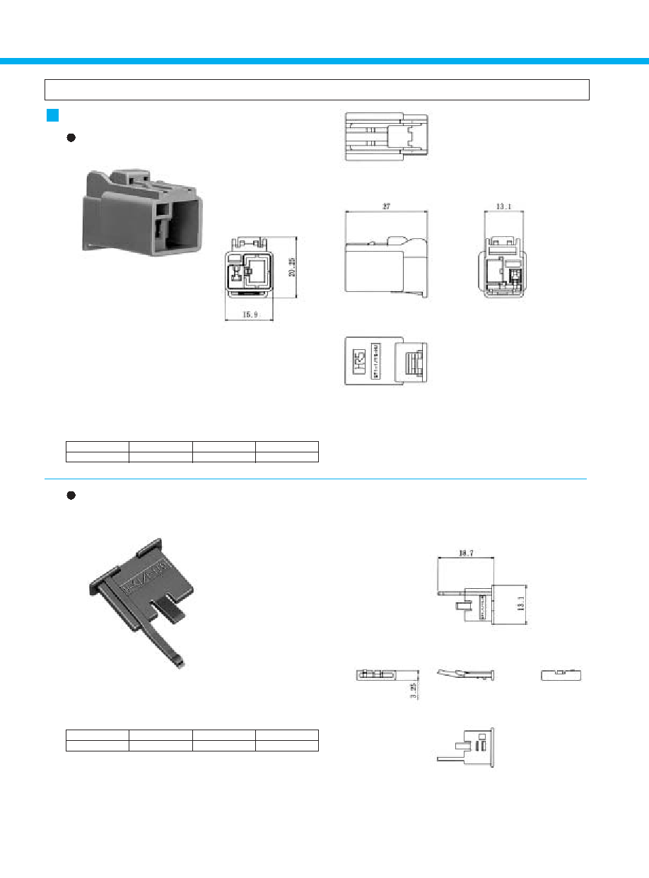
9
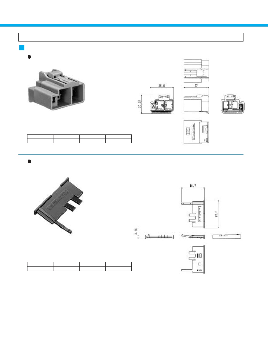
Two-position type-Each Single-Conductor coaxial Cable
Part Number
CL Number
Material
Color
GT1-2S-HU
20
751-0011-7
-20
Light gray
GT1-2S-HU
20
751-0011-7-20
PBT
Orange
GT1-2S-HU
21
751-0011-7-21
Blue
Note: Retainer is optional.
A Configuration Part Number
CL No.
GT1-2S-33R
GT1-2S-53R
GT1-2S-55R
751-0045-9
751-0043-3
751-0044-6
Material
PBT
White
Dark gray
Light blue
o/3
o/5
o/5
o/3
o/3
o/5
Color
Cable Dia.
o/A
o/B
B
GT1-2S-HU
Shown with temporarily inserted retainer
B
GT1-2PP-HU
Shown with temporarily inserted retainer
Note: Mount this item after provisional insertion into the housing, or after terminal insertion.
Part Number
CL Number
Material
Color
GT1-2P/S-R
751-0013-2
PBT
Dark gray
Note 1: This item should be mounted to the GT1-2PP-HU housing after the insertion of terminals.
Note 2: Retainer is optional.
F Connectors
Housing
Retainer (Used with GT1-2S-HU)
Part Number
A Configuration
B
Shown with inserted retainer
Retainer (used with GT1-2S-HU and GT1-2PP-HU)
10
A Configuration Part Number
CL No.
GT1-2PP-33R
GT1-2PP-53R
GT1-2PP-55R
751-0042-0
751-0040-5
751-0041-8
White
Dark gray
Light blue
o/3
o/5
o/5
o/3
o/5
o/3
Color
Cable Dia.
o/A
o/B
Material
Color
White
PBT
Dark gray
Light blue
Note 1: This item should be mounted to the GT1-2PP-HU housing after the insertion of terminals.
Note 2: Retainer is optional.
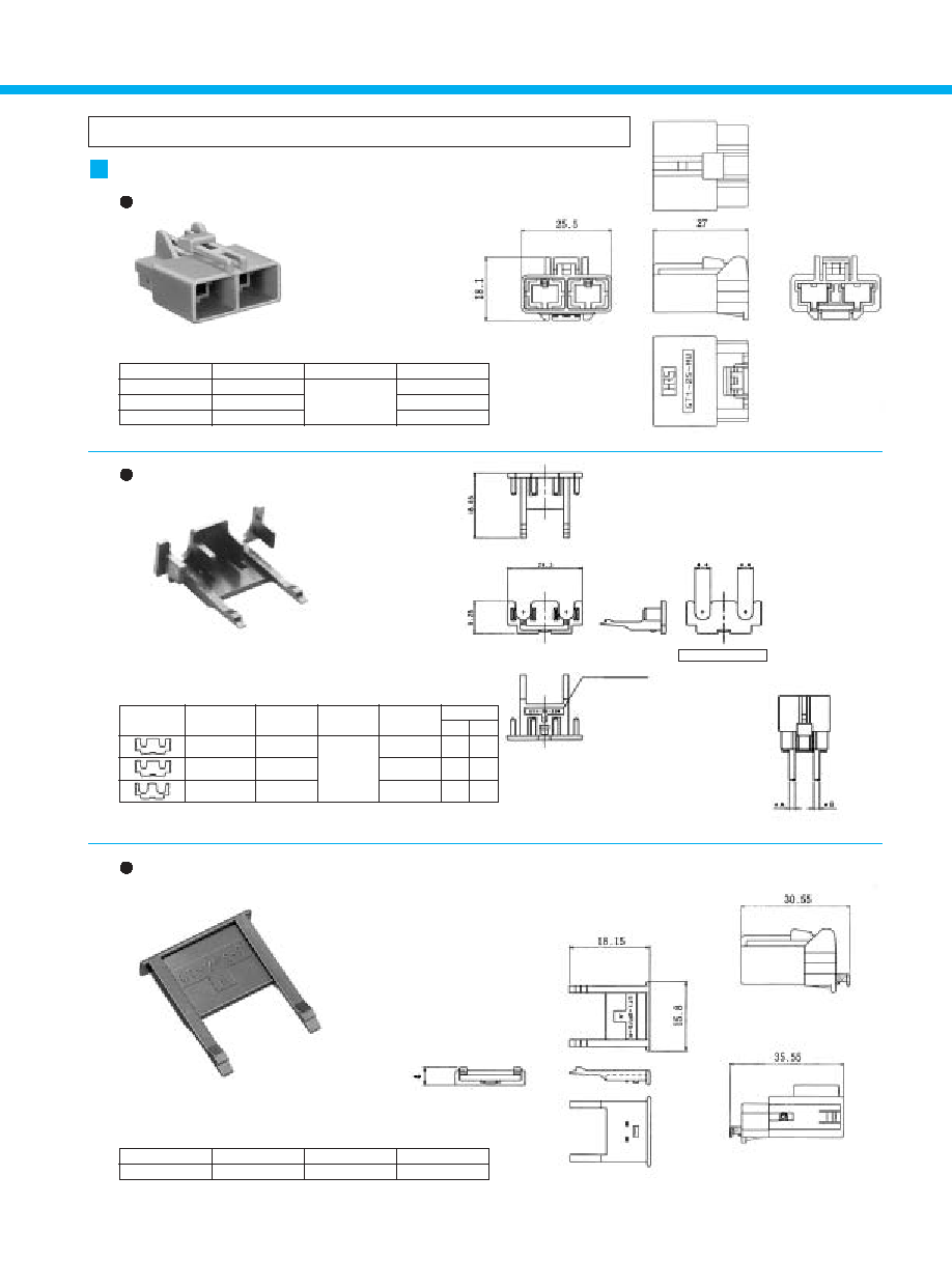
Part Number
CL No.
Color
Remarks
GT1-2PP-HU
(10)
751-0010-4
-20
Light gray
With ground terminal
GT1-2PP-HU(10)
751-0010-4-10
Light gray
Without ground terminal
GT1-2PP-HU(20)
751-0010-4-20
Orange
With ground terminal
GT1-2PP-HU(21)
751-0010-4-21
Blue
With ground terminal
GT1-2PP-HU(40)
751-0010-4-40
Orange
Without ground terminal
GT1-2PP-HU(41)
751-0010-4-41
Blue
Without ground terminal
Note: Retainer is optional.
Item
Material
Finish
Color: Light gray
Housing
PBT
Color: Orange
Color: Blue
Ground terminal
Brass
Tin plating
B
Recommended Mounting Bracket
Dimensions (T=1.5mm)
M Connectors
Housing
Mounting bracket
attachment side
Ground terminal
Tin plating
Retainers (Used with GT1-2PP-HU)
Part Number
A Configuration
B
Shown with inserted retainer
Bracket Mounting portion
11
Part Number
GT7-1618PCF
GT7-2022PCF
GT7A-2022PCF
5,000
3,000
GT7-2022SCF
GT7A-2022SCF
757-0001-1
757-0003-7
#20 to 22
#20 to 22
Part Number
CL No.
Inner Insulator
Diameter
1.4 to 2.4mm
2.6 to 3.1mm
19
Dimension A Packaging
Copper alloy
Material
Tin plating
Finish
Conductor Size
(AWG)
Note 1: Sold by the reel. (See above table for number of Packaging.)
Note 2: This component is used only with applicable HRS housings.
Note 1: Sold by the reel. (See above table for number of Packaging.)
Note 2: This component is used only with applicable HRS housings.
* Reserved for
product expansion
757-0002-4
757-0004-0
#16 to 18
#20 to 22
#20 to 22
CL No.
Inner Insulator
Diameter
1.8 to 2.7mm
1.4 to 2.4mm
2.6 to 3.1mm
Packaging
3,000
5,000
3,000
Material
Brass
Finish
Tin plating
Conductor Size
(AWG)
Power Supply Terminals
F Connector Terminals
M Connector Terminals
5,000
3,000
GT7-2022SCF
GT7A-2022SCF
757-0001-1
757-0003-7
#20 to 22
#20 to 22
Part Number
CL No.
Inner Insulator
Diameter
1.4 to 2.4mm
2.6 to 3.1mm
19
Dimension A Packaging
Copper alloy
Material
Tin plating
Finish
Conductor Size
(AWG)
12
Combination Type (One Single-Conductor Coaxial Cables + One Power contact)
Note: Retainer is optional.
Part Number
CL No.
Material
Color
GT1-1/1S-HU
751-0026-4
PBT
Light gray
Note: Mount this item after provisional insertion into the housing, or after terminal insertion.
Part Number
CL Number
Material
Color
GT1-1/1S-R
751-0028-0
PBT
Dark gray
F Connectors
Housing
Retainer (Used with GT1-1/1S-HU)
13
Part Number
CL No.
Remarks
GT1-1 / 1PP-HU
(00)
751-0025-1
-10
1.5mm
With ground terminal
GT1-1 / 1PP-HU(10)
751-0025-1-10
1.5mm
Without ground terminal
GT1-1 / 1PP-HU(11)
751-0025-1-11
1.0mm
With ground terminal
Note: Used with separate retainer (GT1-1/1PP-R).
Note: Mount this item after provisional insertion into the housing, or after terminal insertion.
Item
Material
Finish
Housing
PBT
Light gray
Ground terminal Phosphor bronze
Tin plating
Part Number
CL Number
Material
Color
GT1-1/1PP-R
751-0027-7
PBT
Dark gray
B
Recommended Mounting Bracket Dimensions (T=1.5mm)
M Connectors
Housing
Mounting bracket
attachment side
Tin plating
Mounting bracket
attachment side
Retainer (exclusively for GT1-1/1PP-HU)
14
Combination Type (Two Single-Conductor Coaxial Cables + One Power contact)
Note1: Mates only with GT1-2/1PP-DS and GT1-2/1PP-HU.
Note2: Used with separate retainer (GT1-2/1S-R).
Part Number
CL No.
Material
Color
GT1-2/1S-HU
751-0019-9
PBT
Light gray
Note: Mount this item after provisional insertion into the housing, or after terminal insertion.
Part Number
CL No.
Material
Color
GT1-2/1S-R
751-0021-0
PBT
Dark gray
F Connectors
Housing
Retainer (used with GT1-2S-HU and GT1-2PP-HU)
15
Note1: Mates only with GT1-2/1S-HU.
Note2: Used with separate retainer (GT1-2/1PP-R).
Item
Material
Finish
Housing
PBT
Light gray
Ground terminal Phosphor bronze
Tin plating
Part Number
CL No.
Remarks
GT1-2/ 1PP-HU
(00)
751-0018-6
-10
1.5mm
With ground terminal
GT1-2/ 1PP-HU(10)
751-0018-6-10
1.5mm
Without ground terminal
GT1-2/ 1PP-HU(11)
751-0018-6-11
1.0mm
With ground terminal
Note: Mount this item after provisional insertion into the housing, or after terminal insertion.
Part Number
CL Number
Material
Color
GT1-2/1PP-R
(22)
751-0020-8
-22
PBT
Dark gray
Part Number
CL No.
Part
Material
Finish
Color
Housing
PBT
----
Light gray
Ground terminal
Phosphor bronze
Tin plating
----
Ground plate
Brass
Tin plating
----
GT1-2/1PP-DS
751-0022-3
Tub terminal for DS 070
Brass
Tin plating
----
0.64X1.1 Terminal
Brass
Tin plating
----
Insulator
PBT
----
Dark gray
Outer terminal
Brass
Tin plating
----
Note1: Mates only with GT1-2/1PP-DS and GT1-2/1PP-HU.
Note 2: Use mounting screws of M3 with nominal diameter 3L-6 (for a panel thickness of 1.6mm)
M Connectors
Housing
Mounting bracket
attachment side
B
Recommended Mounting Bracket
Dimensions (T=1.5mm)
Mounting bracket
attachment side
Ground terminal
Tin plating
Retainer (used with GT1-2/1PP-HU)
Printed Circuit Board Type
Ground terminal
Ground terminal
Ground terminal
For inner conductor
For outer conductor
Panel
Board
B
Recommended Board
Mounting Pattern
B
Recommended Panel
Cut-out

16
Products Listed Below are of the Combination Type (Two Terminals for Use with Single-Conductor Shielded
Cable + One Power Supply Terminal) with Key Positions that Differ from the Products Listed on Previous Pages
Note1: Mates only with GT1-2/1P-DS.
Note2: Used with separate retainer.
Part Number
CL No.
Material
Color
GT1-2/1S-HU(A)
(21)
751-0024-9
-21
PBT
Light gray
GT1-2/1S-HU(A)(21)
751-0024-9-21
PBT
Blue
Item
Material
Finish
Color
----
Light gray
Housing
PBT
----
Blue
0.64X1.1 Terminal
Brass
Tin plating
----
Insulator
PBT
----
Dark gray
Outer terminal
Brass
Tin plating
----
Tub terminal for DS 070
Brass
Tin plating
----
Note1: Mates only with GT1-2/1S-HU(A).
Note 2: Use mounting screws of M3 with nominal diameter 3L-6 (for a panel thickness of 1.6mm)
Part Number
CL No.
Color
GT1-2/1P-DS
(21)
751-0023-6
-21
Light gray
GT1-2/1P-DS(21)
751-0023-6-21
Blue
F Connectors
Housing
M Connector
Printed Circuit Board Type
B
Recommended Board
Mounting Pattern
B
Recommended Panel
Cut-out
Ground terminal
For inner conductor
For outer conductor
Panel
Board
17
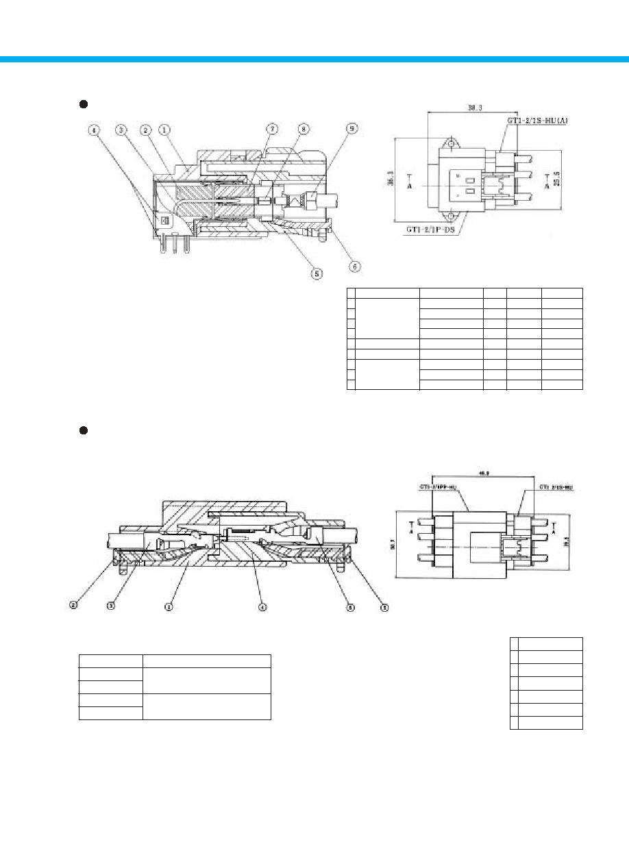
B
Mating, Cross-Sectional View
GT1-2/1P-DS
GT1-2/1S-HU
A
1
2
3
4
5
6
7
8
9
Part Number
Part
Number Used
1
2
2
2
1
1
2
2
2
Material
PBT
PBT
Brass
Brass
PBT
PBT
PBT
Phosphor bronze
Brass
Finish
UL94V-0
UL94V-0
Tin plating
Tin plating
UL94V-0
UL94V-0
UL94V-0
Tin plating
Tin plating
Housing
Insulator
0.64 X 1.1 terminal
Outer terminal
Housing
Retainer
Insulator
Crimp terminal
Outer terminal
GT1-2/1P-DS
(A)
GT1-2/1S-HU(A)
GT1-2/1S-HU
(A)
GT1-1S-2428/1.6C
Currently, the GT7 Series terminals are used for the power supply of the GT1 Series combination type.
The coupled, cross-sectional view of the GT7 terminals of the GT1-2/1 Series appears below.
Part Number
GT1-1/1S-HU
GT1-2/1S-HU
GT1-1/1PP-HU
GT1-2/1PP-HU
Terminal
GT7-2022SCF
GT7A-2022SCF
GT7-2022PCF
GT7A-2022PCF
1
2
3
4
5
6
Part Number
GT1-2/1PP-HU
GT1-2/1PP-R
GT7-2022PCF
GT1-2/1S-HU
GT1-2/1S-R
GT7-2022SCF
Examples of Printed Circuit Board Type and Cable Type
Mating, Top View
Cross Section AA
Example of Cable-to-Cable Type
Cross Section AA
Mating, Top View

18
Mounted Condition Installed
Note 1: This product can be attached to GT1-1PP-HU, GT1-1/1PP-HU, and GT1-2/1PP-HU.
Note 2: Please use the tin plated item when making a ground connection.
Part Number
CL No.
Material
Finish
GT-BK
(01)
751-0039-6
-22
Tin plating
GT-BK(01)
751-0039-6-01
SPCC
Zinc plating
Note: This product cannot be used with GT1K-1S-HU.
Part Number
CL No.
Item
Material
Finish
Top Shield Cover
Tin plating
GT1-1S-1.6CSB
751-0009-5
Bottom Shield Cover
SPCC
Zinc plating
Note: The product normally has sufficient performance without using the shield plate; however, when used in especially high frequency bands (e.g.,
1 GHz and higher), use of the shield plate is recommended so that even higher shielding effectiveness may be obtained.
Part Number
CL No.
Item
Material
Finish
Top Shield Cover
GT1-1P-1.6CSB
751-0008-2
Bottom Shield Cover
Brass
Tin plating
Accessories
Brackets (for M Connector Housing)
F Terminal Shield Cover
M Terminal Shield Plate
Mounted Condition Installed
19
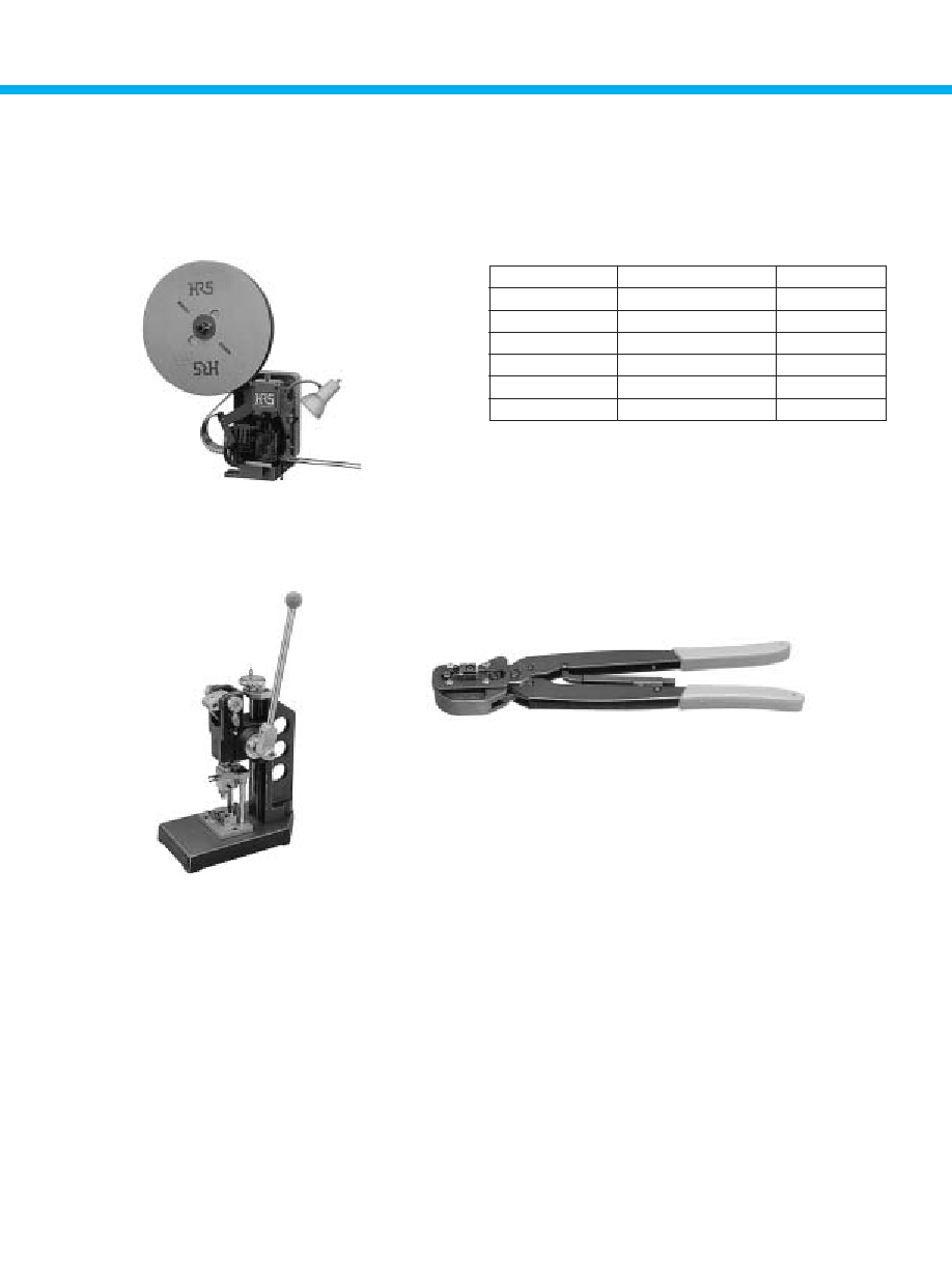
Automatic Crimping Machine
Item
Specification
Remarks
Specification
1.5ton
Stroke Length
30mm
Number of strokes
200spm(50Hz)
240spm(60Hz)
Weight
75kg
Motor
0.2kW
AC100V
Crimping speed
2000 to 4000 per day
Part Number CM-105
Specifications
Hand Tool
Hand Press
B
Termination Tools
User
's manuals are available. Please ask your Hirose Electric account representative.
*Crimp height setting tables are available for each cable type. Please contact your nearest Hirose Electric account representative. Different cables will
require different crimp height settings.
20
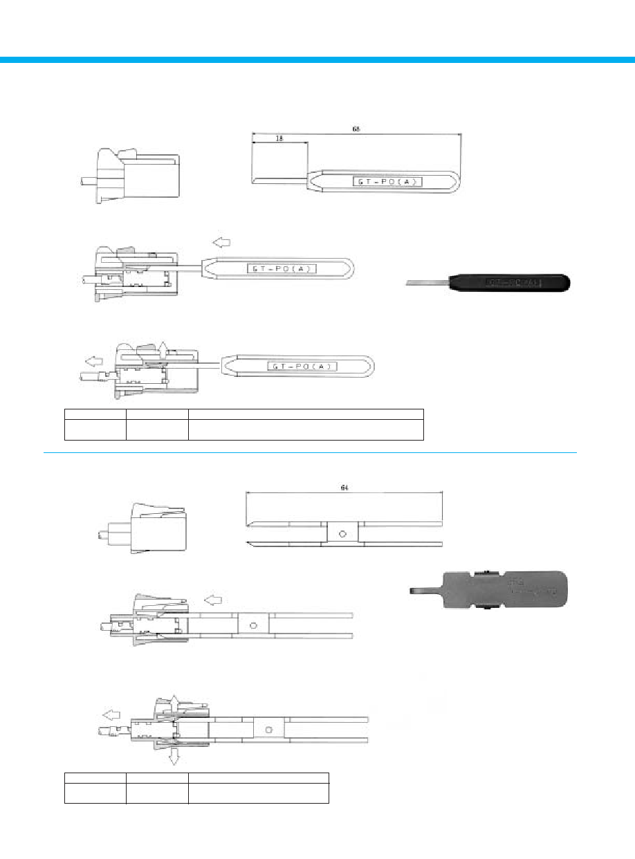
1) For one lance
2) For two lances
1
Insert the extraction tool from the coupling end.
2
Push the lance upward and pull out the terminal.
1
Insert the extraction tool from the coupling end.
2
Push and separate both lances and pull out the terminal.
B
Terminal Extraction Tool
Part Number
CL No.
Used with connectors
GT-PO(A)
780-0006-2
GT1K-1S-HU
GT1-2S-HU
GT1-2PP-HU
GT1-1/1S-HU
GT1-1/1PP-HU
GT1-2/1S-HU
GT1-2/1PP-HU
GT1-2/1S-HU(A)
Part Number
CL No.
Used with connectors
GT1-C-PO
902-5020-1
GT1-1S-HU
GT1-1P-HU
GT1-1PP-HU