
Antenna, Sensor, and Communications Trunk Line Connections
GT17 Series
-- Ideal as Automotive USB Connectors --
<
2 mm pitch
>
Features
All surface shielded construction.
Ideal for use as Automotive USB connectors.
Applications
In-car data communications, etc.
99

Part Number
Conductor Size (AWG)
Outer Diameter
Material
Finish
Copper alloy
Copper alloy
Copper alloy
Tin plating
Tin plating
Tin plating
1.1 to 1.3 mm
0.7 to 1.0 mm
1.1 to 1.3 mm
Packaging
10,000 pcs. per reel
10,000 pcs. per reel
10,000 pcs. per reel
#20 to 22
#24 to 28
#30
GT17-2022SCF
GT17-2428SCF
GT17-30SCF
CL No.
767-0009-0
767-0010-0
767-0064-9
Note: The crimping conditions will differ depending on the construction and material of the cable. In view of this, please make arrangements to
ascertain whether crimping is possible for each cable.
Note: Applicable Cable will have an Insulator diameter of 0.7 to 1.3 mm.
Part Number
GT17V-6DS-2C
CL No.
767-0026-0
Material
Color
Dark gray
Packaging
1
PBT
Part Number
GT17V-6DS-5CF
CL No.
767-0027-2
Material
Finish
Tin plating
Packaging
1
Copper alloy
Outer Diameter
4.8 to 5.2 mm
F Connectors
Center Terminals
(Used with 6, 8, and 10 conductor cable)
F Connectors (6-Conductor Type)
Insulator
Outer terminals
Contact No.1
Contact No.4
Contact No.3
Contact No.6
100

GT17V-6DS-HU
GT17VA-6DS-HU
Part Number
Key Configurations
Material
Color
PBT
PBT
Light gray
Black
1
2
GT17V-6DS-HU
GT17VA-6DS-HU
Note 1: Used with the separate retainer (GT17V-6DS-R).
Note 2: Applicable Cable will have an outside sheath diameter of 4.8 to 5.2 mm.
B
Shown with inserted retainer
CL No.
767-0029-8
767-0030-7
Part Number
Material
Finish
Copper alloy
Tin plating
GT17V-6DS-SC
CL No.
767-0028-5
Packaging
1
Packaging
1
1
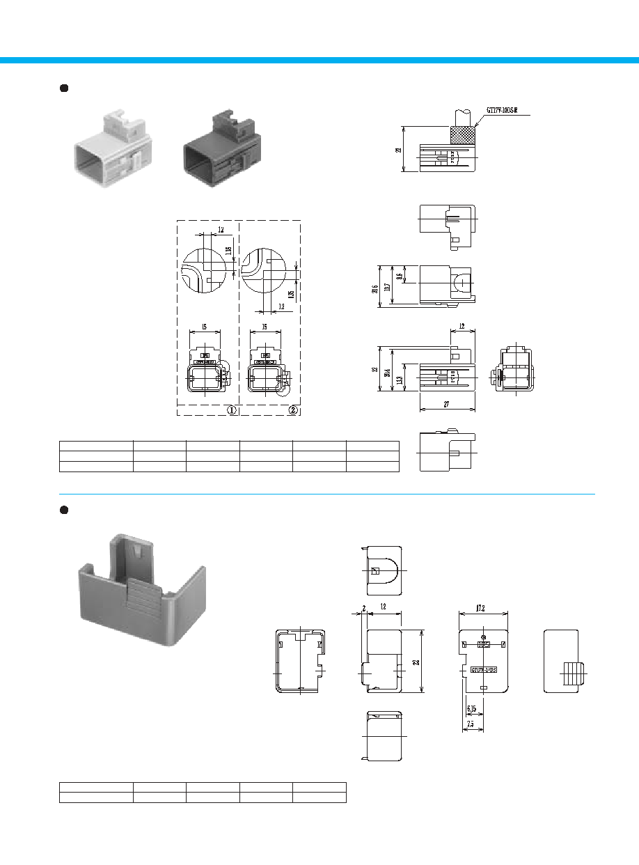
Shield Cover
Housing
Key Configuration
Key Configuration
101

GT17V-6DS-SC
Note: Applicable Cable will have an Insulator diameter of 4.8 to 5.2 mm.
Part Number
GT17V- 6DS-R
CL No.
767-0031-0
Material
Color
Dark gray
Packaging
1
PBT
B
F Connector (6-Conductor Type) Composition Table
Inner Terminal
GT17-2022SCF
GT17-2428SCF
GT17-30SCF
Insulator
GT17V-6DS-2C
Outer Terminal
GT17V-6DS-5CF
B
6-Conductor Type Mating Table
F Connector
GT17V-6DS-HU
GT17VA-6DS-HU
M Connector
GT17V-6DP-DS
GT17VB-6DP-DS
GT17VA-6DP-DS
GT17VC-6DP-DS
Color
Light gray
Black
Shield Cover
Housing
GT17V- 6DS-HU
GT17VA- 6DS-HU
Retainer
GT17V-6DS-R
Retainer (Used with GT17V-6DS-HU and GT17VA-6DS-HU)
102
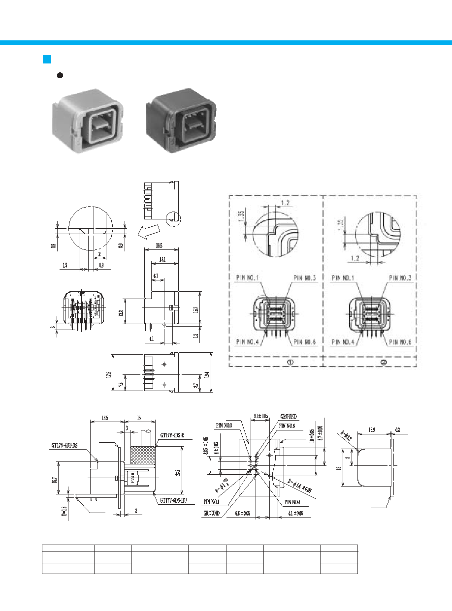
GT17V-6DP-DS
Part Number
GT17V-6DP-DS
CL No.
767-0024-4
GT17VA-6DP-DS
767-0025-7
Material
Color
Light gray
Black
Packaging
1
1
Brass (Center terminal)
Copper alloy (Outer terminals)
PBT (Housing)
Key Configurations
1
2
Direction of Cable Pull-off
Upward with respect to
the mounting surface
B
Panel Insertion
Portion Dimensions
B
Mounted and fully mated
connector assemblies
B
Recommended PCB Mounting Pattern
B
Recommended Panel Cut-out
GT17VA-6DP-DS
M Connectors (6-Conductor Type)
Printed Circuit Board Type
Key Configuration
Key Configuration
Panel
Board
Board
Panel
Board
103

GT17VC-6DP-DS
Part Number
GT17VB-6DP-DS
CL No.
767-0032-2
GT17VC-6DP-DS
767-0033-5
Material
Color
Light gray
Black
Packaging
1
1
Brass (Center terminal)
Copper alloy (Outer terminals)
PBT (Housing)
Key Configurations
3
4
Direction of Cable Pull-off
Downward with respect
to the mounting surface
B
Panel Insertion
Portion Dimensions
GT17VB-6DP-DS
Key Configuration
Key Configuration
Key Configuration
B
Mounted and fully mated
connector assemblies
B
Recommended PCB Mounting Pattern
B
Recommended Panel Cut-out
Panel
Board
Board
Panel
Board
104

Part Number
GT17-8DS-2C
CL No.
767-0005-0
Material
Packaging
1
PBT
Color
Dark gray
Part Number
GT17-8DS-SC
CL No.
767-0006-2
Material
Packaging
1
Brass
Finish
Tin plating
Part Number
GT17-8DS-7CF
CL No.
767-0007-5
Material
Packaging
1
Phosphor bronze
Finish
Tin plating
Outer Diameter
6.8 to 7.2 mm
Note: The crimping conditions will differ depending on the construction and material of the cable. In view of this, please make arrangements to ascertain
whether crimping is possible for each cable.
Note: Applicable Cable will have an Insulator diameter of 0.7 to 1.3 mm.
F Connectors (8-Conductor Type)
Insulator
Outer terminals
Shield Cover
105

GT17-8DS-HU
GT17A-8DS-HU
Part Number
GT17-8DS-HU
CL No.
767-0003-4
Material
Color
Light gray
Packaging
1
PBT
Key Configurations
1
GT17A-8DS-HU
767-0004-7
Black
1
PBT
2
Note 1: Used with the separate retainer (GT17-8DS-R).
Note 2: Applicable Cable will have an outside sheath diameter of 6.8 to 7.2 mm.
Part Number
GT17-8DS-R
CL No.
767-0008-8
Material
Color
Dark gray
PBT
Packaging
1
Note: Applicable Cables will have an outside sheath diameter of 6.8 to 7.2 mm.
B
Shown with inserted retainer
Housing
Key Configuration
Key Configuration
Retainer
106

107
B
F Connector (8-Conductor Type) Composition Table
Inner Terminal
GT17-2022SCF
GT17-2428SCF
GT17-30SCF
Insulator
GT17-8DS-2C
Outer Terminal
Shield Cover
GT17-8DS-SC
Retainer
GT17-8DS-R
GT17-8DS-7CF
Housing
GT17-8DS-HU
GT17A-8DS-HU
B
8-Conductor Type Mating Table
F Connector
GT17-8DS-HU
GT17A-8DS-HU
M Connector
GT17-8DP-DS
GT17B-8DP-DS
GT17A-8DP-DS
GT17C-8DP-DS
Color
Light gray
Black

108
GT17-8DP-DS
GT17A-8DP-DS
Part Number
GT17-8DP-DS
CL No.
767-0001-9
GT17A-8DP-DS
767-0002-1
Material
Color
Light gray
Black
Packaging
1
1
Brass (Center terminal)
Key Configurations
1
Direction of Cable Pull-off
Upward with respect to
the mounting surface
2
Phosphor bronze (Outer terminals)
PBT (Housing)
M Connectors (8-Conductor Type)
Printed Circuit Board Type
B
Panel Insertion
Portion Dimensions
Key Configuration
Key Configuration
Panel
Board
Board
Panel
Board
B
Mounted and fully mated
connector assemblies
B
Recommended PCB Mounting Pattern
B
Recommended Panel Cut-out

109
GT17B-8DP-DS
GT17C-8DP-DS
B
Panel Insertion
Portion Dimensions
Key Configuration
Key Configuration
B
Mounted and fully mated
connector assemblies
B
Recommended PCB Mounting Pattern
B
Recommended Panel Cut-out
Panel
Board
Board
Panel
Board
Part Number
GT17B-8DP-DS
CL No.
767-0020-3
GT17C-8DP-DS
767-0021-6
Material
Color
Light gray
Black
Packaging
1
1
Brass (Center terminal)
Key Configurations
3
Direction of Cable Pull-off
Downward with respect to
the mounting surface
4
Phosphor bronze (Outer terminals)
PBT (Housing)

110
No.1
No.6
11.45
8.15
16.9
No.5
No.10
10
--
12.9
12.3
13.15
38.6
22.9
9
(
11.3
)
Note: Applicable Cable will have an Insulator diameter of 0.7 to 1.3 mm.
Note: The crimping conditions will differ depending on the construction and material of the cable. In view of this, please make arrangements to
ascertain whether crimping is possible for each cable.
Part Number
GT17V-10DS-SC
CL No.
767-0038-9
Material
Copper alloy
Finish
Tin plating
Packaging
1
F Connectors (10-Conductor Type)
Insulator (used for both right-angle and straight types)
Part Number
GT17V-10DS-2C
CL No.
767-0036-3
Material
Packaging
1
PBT
Color
Dark gray
Outer terminals (Right Angle)
Part Number
GT17V-10DS-8CF
CL No.
767-0037-6
Material
Finish
Tin plating
Packaging
1
Copper alloy
Outer Diameter
7.5 to 8.0 mm
Shield Cover (Right Angle)
Part Number
GT17V-10DS-HU
CL No.
767-0039-1
Material
Color
Light gray
Key Configurations
1
Packaging
1
PBT
GT17VA-10DS-HU
767-0040-0
Black
2
1
PBT
Part Number
GT17V-10DS-R
CL No.
767-0041-3
Material
Color
Dark gray
Packaging
1
PBT
Note: Applicable Cable will have an outside sheath diameter of 7.5 to 8.0 mm.
B
Shown with inserted retainer
Note: Used with the separate retainer (GT17-10DS-R).
GT17V-10DS-HU
GT17VA-10DS-HU
Housing (Right-angle Type)
Key Configuration
Key Configuration
Retainer (Right-angle Type)
111

12.3
9
33.85
26
12.9
(
11.3
)
12.3
13.2
4.75
7.9
26.7
Note: The crimping conditions will differ depending on the construction and material of the cable. In view of this, please make arrangements to
ascertain whether crimping is possible for each cable.
Part Number
GT17VS-10DS-SC
CL No.
767-0060-8
Material
Copper alloy
Finish
Tin plating
Packaging
1
Note: Applicable Cables will have an outside sheath diameter of 7.5 to 8.0 mm.
8.3
17.2
11
15.6
13.3
GT17VS-10DS
Note: Applicable Cables will have an outside sheath diameter of 7.5 to 8.0 mm.
Outer terminals (Straight Type)
Part Number
GT17VS-10DS-8CF
CL No.
767-0059-9
Material
Finish
Tin plating
Packaging
1
Copper alloy
Outer Diameter
7.5 to 8.0 mm
Shield Cover (Straight Type)
Retainer (Straight Type)
Part Number
GT17VS-10DS-R
CL No.
767-0063-6
Material
Color
Dark gray
Packaging
1
PBT
112

113
Note 1: Used with the separate retainer (GT17-10DS-R).
Note 2: Applicable Cable will have an outside sheath diameter of 7.5 to 8.0 mm.
B
F Connector (10-Conductor Type) Composition Table
Inner Terminal
GT17-2022SCF
GT17-2428SCF
GT17-30SCF
Insulator
GT17V-10DS-2C
Outer Terminal
Shield Cover
GT17V-10DS-SC
GT17VS-10DS-SC
Retainer
GT17V-10DS-R
GT17VS-10DS-R
GT17V-10DS-8CF
GT17VS-10DS-8CF
Housing
GT17V-10DS-HU
GT17VA-10DS-HU
GT17VS-10DS-HU
GT17VSA-10DS-HU
B
10-Conductor Type Mating Table
F Connector
GT17V-10DS-HU
GT17VS-10DS-HU
GT17VA-10DS-HU
GT17VSA-10DS-HU
M Connector
GT17V-10DP-DS
GT17V-10DP-DSA
GT17V-10DP-DS -SB
GT17VA-10DP-DS
GT17VA-10DP-DSA
GT17VA-10P-DS-SB
Color
Light gray
Black
B
Shown with inserted retainer
GT17VS-10DS-HU
GT17VSA-10DS-HU
Housing (Straight Type)
Part Number
GT17VS-10DS-HU
CL No.
767-0061-0
Material
Color
Light gray
Packaging
1
PBT
Key Configurations
1
GT17VSA-10DS-HU
767-0062-3
Black
1
PBT
2
Key Configuration
Key Configuration

Part Number
GT17V-10DP-DS
CL No.
767-0034-8
GT17VA-10DP-DS
767-0035-0
Material
Color
Light gray
Black
Packaging
1
1
Brass (Center terminal)
Key Configurations
1
Direction of Cable Pull-off
Upward with respect to
the mounting surface
2
Copper alloy (Outer terminals)
PBT (Housing)
B
Recommended PCB Mounting Pattern
B
Recommended Panel Cut-out
B
Mounted and fully mated connector assemblies
B
Mounted and fully mated connector assemblies
GT17V-10DP-DS
GT17VA-10DP-DS
M Connectors (10-Conductor Type)
Printed Circuit Board Type (Right-angle Type)
B
Panel Insertion
Portion Dimensions
Key Configuration
Key Configuration
Panel
Board
Panel
Board
Panel
Board
114

GT17V-10DP-DSA
GT17VA-10DP-DSA
B
Recommended PCB Mounting Pattern
B
Recommended Panel Cut-out
B
Mounted and fully mated connector assemblies
B
Mounted and fully mated connector assemblies
Printed Circuit Board Type (Straight Type)
B
Panel Insertion
Portion Dimensions
Key Configuration
Key Configuration
Panel
Board
Board
Panel
Board
Part Number
GT17V-10DP-DSA
CL No.
767-0067-7
GT17VA-10DP-DSA
767-0068-0
Material
Color
Light gray
Black
Packaging
1
1
Brass (Center terminal)
Key Configurations
1
Direction of Cable Pull-off
Upward with respect to
the mounting surface
2
Copper alloy (Outer terminals)
PBT (Housing)
115

Part Number
GT17V-10DP-DS-SB
CL No.
767-0069-2
GT17VA-10DP-DS-SB
767-0070-1
Material
Color
Light gray
Black
Packaging
1
1
Brass (Center terminal)
Key Configurations
1
Direction of Cable Pull-off
Upward with respect to
the mounting surface
2
Copper alloy (Outer terminals)
PBT (Housing)
Brass (Shield)
B
Recommended Panel Cut-out
B
Recommended PCB Mounting Pattern
B
Mounted and fully mated connector assemblies
B
Mounted and fully mated connector assemblies
GT17V-10DP-DS-SB
GT17VA-10DP-DS-SB
Printed Circuit Board Type (Shield Reinforced Type)
Panel
Board
Key Configuration
Key Configuration
Panel
Board
Panel
Board
Panel
Board
Panel
116

B
Wiring Method
117
Strip the outside sheath.
Outside shield
Outside sheath
Cut the shield and intermediate material to
expose the wire and braid.
Bend back the drain wire over the sheath.
Wrap with copper tape.
Strip the wire leads.
Crimp the center terminals.
Insert the center terminals into the insulator.
Drain wire
Drain wire
Signal wires
Copper tape
Wire
Center terminal
Insulated case
GT17V-10DS-HU Harness Finish
Insert the insulator into the Outer terminal.
Outer terminal
Insert the Shield Cover.
Fold back the Outer terminal.
Crimp the Outer terminal.
Insert the Outer terminal into the housing.
Insert the retainer.
Completion
Shield Cover
Housing
Retainer

118
Automatic Crimping Machine
Item
Specification
Remarks
Specification
1.5ton
Stroke Length
30mm
Number of strokes
200spm (50Hz)
240spm (60Hz)
Weight
75kg
Motor
0.2kW
AC100V
Crimping speed
2000 to 4000 pcs. per day
Part Number CM-105
B
Specifications
Hand Press
B
Termination Tools
User's manuals are available. Please ask your
Hirose Electric account representative.
* Crimp height setting tables are available for each cable type. Please contact your nearest Hirose Electric account representative.
Different cables will require different crimp height settings.
Insert the insulator into the Outer terminal.
Crimp the Outer terminal.
Insert the Shield Cover.
Outer terminal
GT17VS-10DS-HU Harness Finish
Shield Cover
Insert the Outer terminal into the housing.
Insert the retainer.
Completion
Housing
Retainer