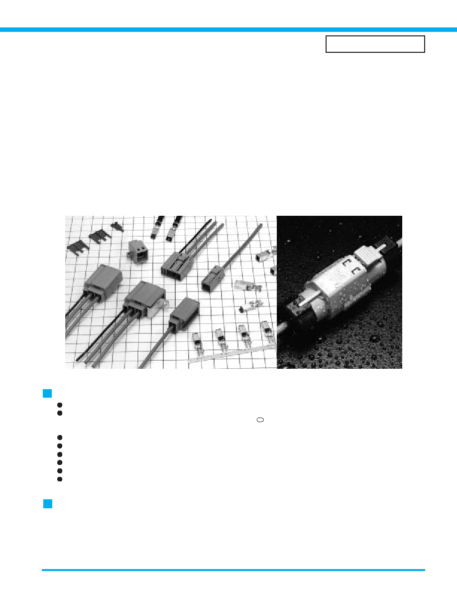
Coaxial cable connection of Antennas, Sensors, and Communication Trunk Lines
Termination of coaxial cables in automotive, medical and instrumentation applications
utilizes a single motion to crimp the center conductor, shield and outer insulation.
GT5 Series
-- Connectors for coaxial cables --
<
Several types and configurations: In-line, board mounted, combinations of
coaxial cable with signal/power, Multi-position and color/ keying variations.
>
Features
USCAR Standard titled "Square Outer Conductor (SAE/USCAR-19)" excludes Water Proof type (GT5W)
Cost efficient termination
Highly efficient and reliable single motion "Twin Crimp
TM
" termination allows high volume production with
semi-automatic equipment.
Space-saving Design
Lock-release latching system
Shock / vibration resistant electrical connections
Verification of the full contact insertion
Color and polarizing variations
Excellent High Frequency Performance
Refer to V.S.W.R. data on the following pages.
Applications
In-car communication, car sensors (temperature, pressure), automotive audio systems, GPS antenna systems,
RACS antenna audio/video antenna systems, CRT displays, medical and measuring instrumentation, variety of
communication equipment, office automation equipment, LAN systems.
*
"Twin Crimp "is a registered trade mark of Hirose Electric.
SAE/USCAR-19
27
B
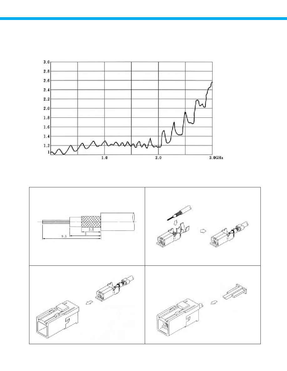
Test Data (Using 1.5D-2V Type cable)
High Frequency Characteristics (V.S.W.R.)
B
Termination sequence
Note: Typical data using fully assemblied and connected GT5-1S-HU and the GT5-1PP-HU.
2. Crimp the cable to the terminal.
4. Fully insert the retainer.
3. Insert the terminal in the housing until is fully locked.
1. Strip the cable.
28

Terminals for coaxial shielded cable
F Connector Terminals
*
*
*
*
*
*
*
GT5-30/0.7-1.5SCF
GT5-2428/1.6-2.5SCF
GT5-30/1.6-2.9SCF
GT5-2428/1.6-2.9SCF
GT5-2022/1.6-2.9SCF
GT5-2022/F2.7-3.5SCF
GT5-2022/F3.3-3.8SCF
GT5-30/3.3-5SCF
GT5-2428/F3.3-5SCF
GT5-2022/F3.3-5SCF
GT5-30/F4-5SCF
GT5-2428/F4-5SCF
GT5-2022/F4-5SCF
755-0065-1
755-0078-3
755-0022-9
755-0002-1
755-0071-4
755-0077-0
755-0054-5
755-0016-6
755-0012-5
755-0034-8
755-0020-3
755-0024-4
755-0036-3
#30 or equivalent
#30 or equivalent
#24 to 28 or equivalent
#24 to 28 or equivalent
#20 to 22 or equivalent
#20 to 22 or equivalent
#20 to 22 or equivalent
#30 or equivalent
#24 to 28 or equivalent
#20 to 22 or equivalent
#30 or equivalent
#24 to 28 or equivalent
#20 to 22 or equivalent
Part Number
CL No.
Inner Insulation
Diameter
0.6 to 0.9mm
1.5 to 2.0mm
1.5 to 2.0mm
2.4 to 2.9mm
2.5 to 2.9mm
2.5 to 2.9mm
3.0 to 3.6mm
1.4 to 1.8mm
2.3 to 2.7mm
2.6 to 3.4mm
3.3 to 3.7mm
3.6 to 4.0mm
4.6 to 5.0mm
4.6 to 5.0mm
1,300 pcs. per reel
1,300 pcs. per reel
1,300 pcs. per reel
1,100 pcs. per reel
1,100 pcs. per reel
1,100 pcs. per reel
1,100 pcs. per reel
Outer
Diameter
Packaging
Conductor Size (AWG)
Note: Products marked with an asterisk (*) indicate polyethylene foam insulation.
Part
Insulator
Crimp terminals
Outer terminals
Material
PBT
Phosphor bronze
Brass
Finish
Color: Dark gray
Tin plating
Tin plating
*
*
*
*
*
*
*
GT5-30/0.7-1.5PCF
GT5-30/1.6-2.9PCF
GT5-2428/1.6-2.9PCF
GT5-2022/1.6-2.9PCF
GT5-2022/F2.7-3.5PCF
GT5-2022/F3.3-3.8PCF
GT5-30/F3.3-5PCF
GT5-2428/F3.3-5PCF
GT5-2022/F3.3-5PCF
GT5-30/F4-5PCF
GT5-2428/F4-5PCF
GT5-2022/F4-5PCF
755-0017-9
755-0021-6
755-0001-9
755-0094-0
755-0076-8
755-0053-2
755-0015-3
755-0011-2
755-0033-5
755-0019-4
755-0023-1
755-0035-0
#30 or equivalent
#30 or equivalent
#24 to 28 or equivalent
#20 to 22 or equivalent
#20 to 22 or equivalent
#20 to 22 or equivalent
#30 or equivalent
#24 to 28 or equivalent
#20 to 22 or equivalent
#30 or equivalent
#24 to 28 or equivalent
#20 to 22 or equivalent
Part Number
CL No.
Inner Insulation
Diameter
0.6 to 0.9mm
1.5 to 2.0mm
2.4 to 2.9mm
2.5 to 2.9mm
2.5 to 2.9mm
3.0 to 3.6mm
1.4 to 1.8mm
2.6 to 3.4mm
3.3 to 3.7mm
3.6 to 4.0mm
4.6 to 5.0mm
4.6 to 5.0mm
900 pcs. per reel
900 pcs. per reel
900 pcs. per reel
900 pcs. per reel
900 pcs. per reel
900 pcs. per reel
Outer
Diameter
Packaging
Conductor Size (AWG)
Note: Products marked with an asterisk (*) indicate polyethylene foam insulation.
Part
Insulator
Crimp terminals
Outer terminals
Material
PBT
Brass
Brass
Finish
Color: Dark gray
Tin plating
Tin plating
M Connector Terminals
Low-insertion M Connector Terminals
Part
Insulator
Crimp terminals
Outer terminals
Material
PBT
Brass
Brass
Finish
Color: Dark gray
Tin plating
Tin plating
GT5L-30/0.7-1.5PCF
GT5L-30/1.6-2.9PCF
GT5L-2428/1.6-2.9PCF
GT5L-2428/1.6-2.5PCF
755-0068-0
755-0067-7
755-0066-4
755-0079-6
#30 or equivalent
#30 or equivalent
#24 to 28 or equivalent
#24 to 28 or equivalent
Part Number
HRS No.
Inner Insulation
Diameter
0.6 to 0.9mm
1.5 to 2.0mm
1.4 to 1.8mm
2.6 to 3.4mm
900 pcs. per reel
900 pcs. per reel
Outer
Diameter
Packaging
Conductor Size (AWG)
29
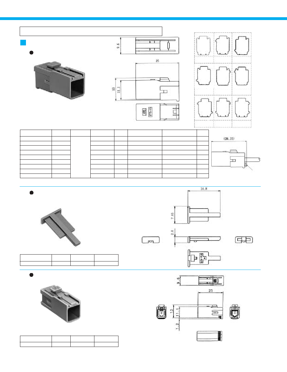
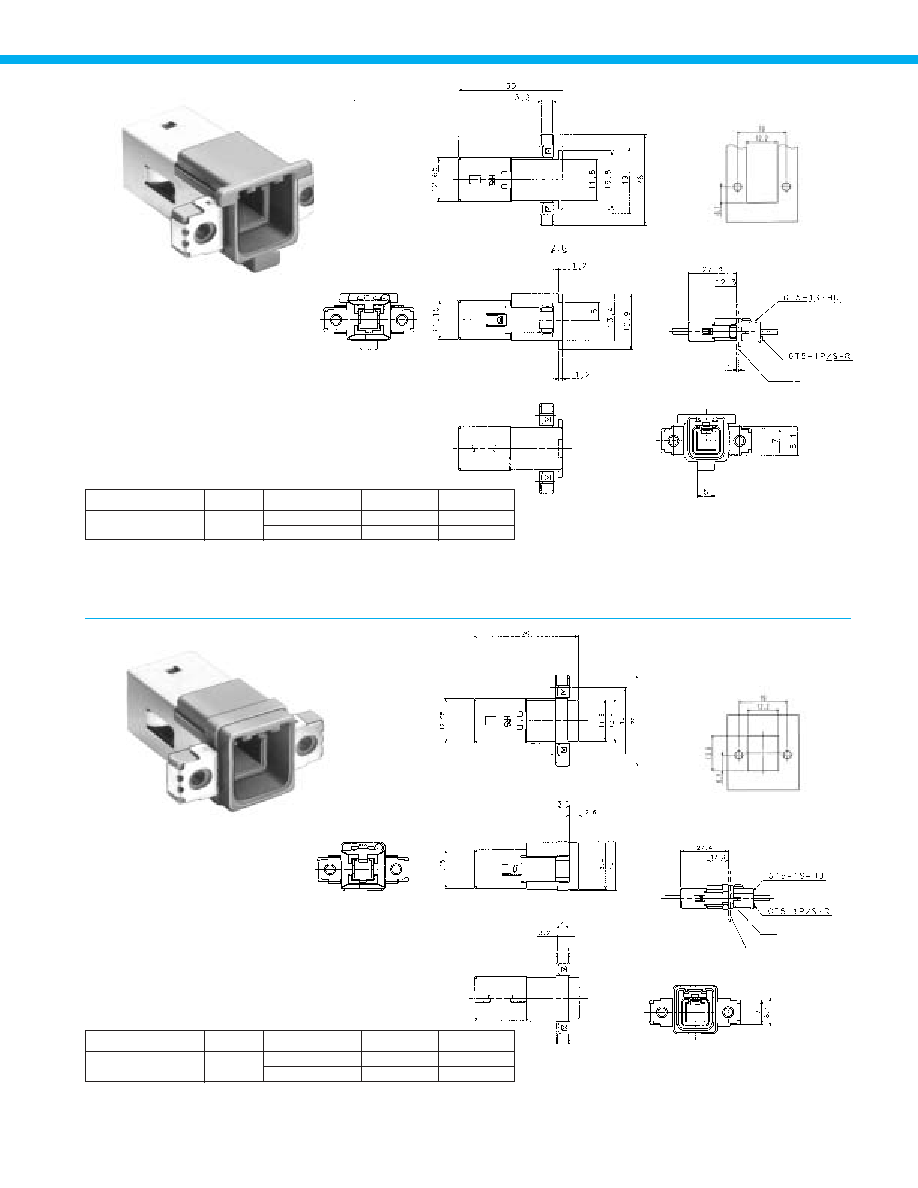
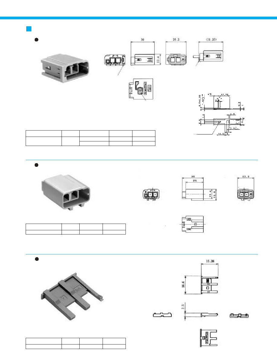
F Connectors
For Single-Conductor coaxial shielded cable
Housing
GT5R-1S/ HU
GT5-1S-HU
Terminal extraction tool: GT-PO(A), Note 1: concept only
Figure q
Figure w
Figure e
Figure r
Figure t
Figure y
Figure u
Figure i
Figure o
Retainer (-Optional-Used with the housings: GT5-1S-HU, GT5-1PP-
HU, GT5N-1PP-HU, GT5H-1PP-HU, and GT5-1PB-HU)
Housing (Not requiring use of the retainer)
Part Number
GT5-1P/S-R
CL No.
Material
Color
755-0006-2
PBT
Dark gray
Part Number
GT5R-1S-HU
CL No.
Material
Color
755-0047-0
PBT
Light gray
Terminal extraction tool: GT-PO(A)
B
Keying Configurations
GT5-1S-HU
GT5-1S-HU(A)
GT5-1S-HU(B)
GT5-1S-HU(C)
GT5-1S-HU(D)
GT5-1S-HU(E)
GT5-1S-HU( I )
GT5-1S-HU(J)
GT5-1S-HU(K)
755-0004-7
755-0037-6
755-0038-9
755-0080-5
755-0081-8
755-0082-0
Note 1
Note 1
Note 1
Light gray
Brown
Green
Blue
Purple
Pink
Black
Cream white
Pastel orange
Figure q
Figure w
Figure e
Figure r
Figure t
Figure y
Figure u
Figure i
Figure o
GT5-1PP-HU
GT5-1PP-HU(A)
GT5-1PP-HU(B)
GT5-1PP-HU(C)
GT5-1PP-HU(D)
GT5-1PP-HU(E)
GT5-1PP-HU( I )
GT5-1PP-HU(J)
GT5-1PP-HU(K)
GT5-1P-DS
GT5-1P-DS(A)
GT5-1P-DS(B)
GT5-1P-DS(C)
GT5-1P-DS(D)
GT5-1P-DS(E)
GT5-1P-DS( I )
GT5-1P-DS(J)
GT5-1P-DS(K)
Part Number
CL No.
Material Color
Key polarizing
code
Corresponding M Connector
Housing- In-line
Corresponding M Connector
Assembly- Board Mounting
-
A
B
C
D
E
I
J
K
USCAR-19
Coding
PBT
B
Shown with inserted retainer.
Retainer
30
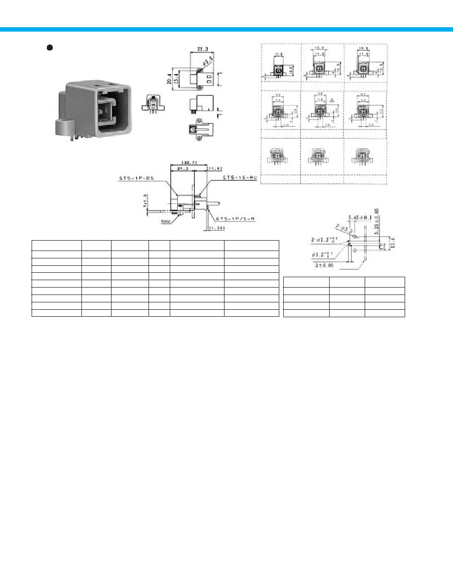
Housing
Figure q
Figure w
Figure e
Figure r
Figure t
Figure y
Figure u
Figure i
Figure o
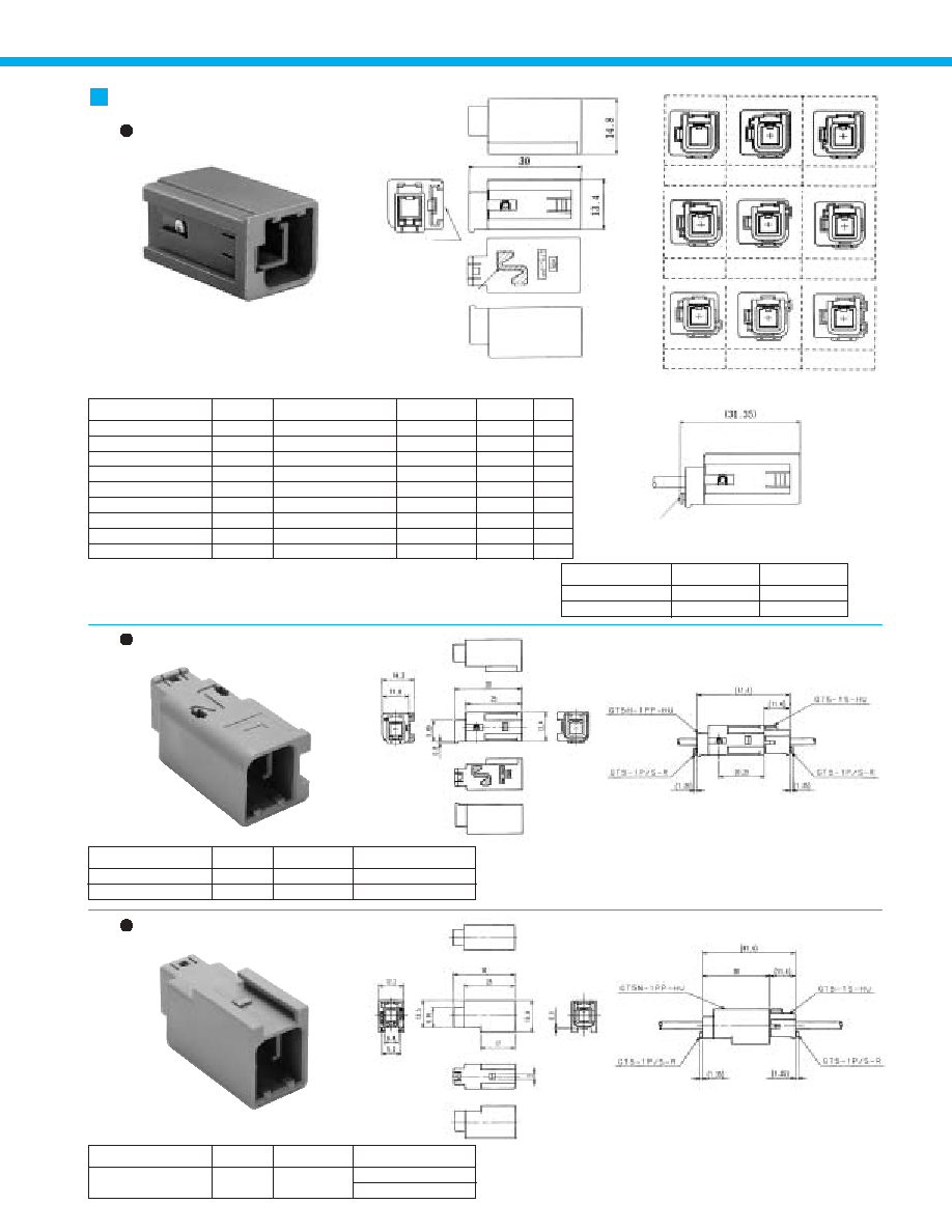
M Connectors
GT5-1PP-HU
GT5-1PP-HU(A)
GT5-1PP-HU(B)
GT5-1PP-HU(C)
GT5-1PP-HU(D)
GT5-1PP-HU(E)
GT5-1PP-HU( I )
GT5-1PP-HU(J)
GT5-1PP-HU(K)
755-0005-0
755-0039-1
755-0040-0
755-0103-9
755-0104-1
755-0105-4
Note 1
Note 1
Note 1
Light Gray
Brown
Green
Blue
Purple
Pink
Black
Cream white
Pastel orange
Figure q
Figure w
Figure e
Figure r
Figure t
Figure y
Figure u
Figure i
Figure o
-
A
B
C
D
E
I
J
K
Part Number
CL No.
Corresponding F Connector
Housing
Color
Key polarizing
code
USCAR-19
Coding
* Refer to pages 32 and 34 for panel brackets used with in-line connectors.
* Terminal extraction tool: GT-PO(A)
Note 1: concept only
GT5-1S-HU
GT5-1S-HU(A)
GT5-1S-HU(B)
GT5-1S-HU(C)
GT5-1S-HU(D)
GT5-1S-HU(E)
GT5-1S-HU( I )
GT5-1S-HU(J)
GT5-1S-HU(K)
Part
Housing
Ground terminal
Material
PBT
Phosphor bronze
Finish
Color: Dark gray
Tin plating
Mounting bracket
attachment side
Outside ground connection
Housing (For use with H type mounting
bracket)
Housing (For use with N type mounting
bracket)
B
Fully mated connector assemblies.
B
Fully mated connector assemblies.
Part Number
GT5H-1PP-HU (10)
GT5H-1PP-HU (41)
CL No.
755-0093-7 10
755-0093-7 41
Color
Corresponding F Connector
Housing
Light Gray
Blue
GT5-1S-HU
GT5R-1S-HU
Part Number
GT5N-1PP-HU
CL No.
755-0090-9
Color
Corresponding F Connector
Housing
Light Gray
GT5-1S-HU
GT5R-1S-HU
B
Keying Configurations
B
Shown with inserted retainer.
Retainer
31

Housings
Panel mounting, enhanced
shielding configuration
Part Number
GT5A-1PP-HU
CL No.
755-0025-7
Part
Material
Finish
Housing
Ground terminal
PBT
Brass
Color: Light gray
Tin plating
[
]
B
Recommended Panel Cut-out
B
Mounted and fully mated connector
assemblies
B
Recommended Panel Cut-out
B
Mounted and fully mated
connectorassemblies
Panel
thickness:1.6
M 3
Note 1: Terminal extraction tool: GT-PO(A)
Note 2: Retainer is optional.
Note 3: Use mounting screws of M3 with nominal diameter 3L-6 (for a panel thickness of 1.6 mm).
Part Number
GT5P-1PP-HU
CL No.
755-0030-7
Part
Material
Finish
Housing
Ground terminal
PBT
Brass
Color: Light gray
Tin plating
Note 1: Terminal extraction tool: GT-PO(A)
Note 2: Retainer is optional.
Note 3: Use mounting screws of M3 with nominal diameter 3L-6 (for a panel thickness
of 1.6 mm).
1
Panel
thickness:1.6
32
Chassis
Assembly Diagram (1:1)
Chassis
Assembly Diagram (1:1)
B
Recommended Panel Cut-out
B
Recommended Panel Cut-out
Part Number
GT5B-1PP-HU
CL No.
755-0051-7
Part
Material
Finish
Housing
Ground terminal
PBT
Copper alloy
Color: Light gray
Tin plating
Note 1: Terminal extraction tool: GT-PO(A) with nominal diameter 3L-6 (for a board
thickness of 1.6 mm).
Note 2: Retainer is optional.
Note 3: Use mounting screws of M3 with nominal diameter 3L-6 (for a panel thickness
of 1.6 mm).
Part Number
GT5S-1PP-HU
CL No.
755-0050-4
Part
Material
Finish
Housing
Ground terminal
PBT
Copper alloy
Color: Light gray
Tin plating
Note 1: Terminal extraction tool: GT-PO(A) with nominal diameter 3L-6 (for a board
thickness of 1.6 mm).
Note 2: Retainer is optional.
Note 3: Use mounting screws of M3 with nominal diameter 3L-6 (for a panel thickness
of 1.6 mm).
B
Mounted and fully mated connector
assemblies
B
Mounted and fully mated connector
assemblies
33
Connector assembly, Printed
Circuit Board Mounting Type
Figure q
Figure w
Figure e
GT5-1P-DS
GT5-1P-DS(A)
GT5-1P-DS(B)
GT5-1P-DS(C)
GT5-1P-DS(D)
GT5-1P-DS(E)
GT5-1P-DS( I )
GT5-1P-DS(J)
GT5-1P-DS(K)
755-0007-5
755-0041-3
755-0042-6
755-0083-3
755-0084-6
755-0085-9
Note 2
Note 2
Note 2
Figure q
Figure w
Figure e
Figure r
Figure t
Figure y
Figure u
Figure i
Figure o
GT5-1P-DS
GT5-1P-DS(A)
GT5-1P-DS(B)
GT5-1P-DS(C)
GT5-1P-DS(D)
GT5-1P-DS(E)
GT5-1P-DS( I )
GT5-1P-DS(J)
GT5-1P-DS(K)
GT5-1S-HU
GT5-1S-HU(A)
GT5-1S-HU(B)
GT5-1S-HU(C)
GT5-1S-HU(D)
GT5-1S-HU(E)
GT5-1S-HU( I )
GT5-1S-HU(J)
GT5-1S-HU(K)
Part Number
CL No.
Color
Key polarizing
code
M Connector-Board Type
Corresponding F Connector
Housing
Note1: Use mounting screws of M3 with nominal diameter 3L-6 (for a board thickness of 1.6 mm).
Note2: concept only
Light Gray
Brown
Green
Blue
Purple
Pink
Black
Cream white
Pastel orange
Part
Housing
0.65 x 1.1 Terminals
Insulator
Outer terminals
Material
PBT
Brass
PBT
Phosphor bronze
Finish
-
Tin plating
Dark gray
Tin plating
B
Recommended PCB Mounting Pattern
For outer conductor
For inner conductor
Outlines
B
Diagram of Mated Connector in Use
Figure r
Figure t
Figure y
Figure u
Figure i
Figure o
11.8
3
34
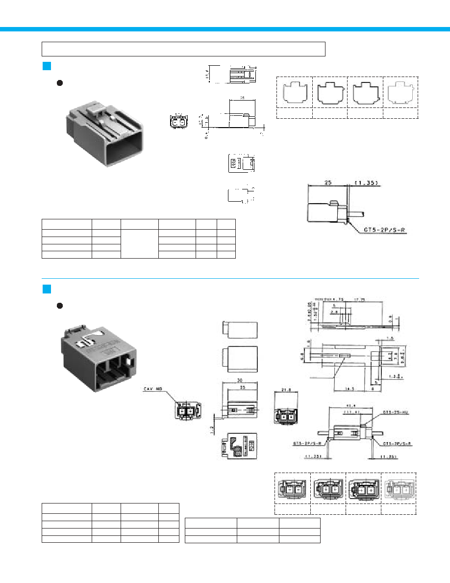
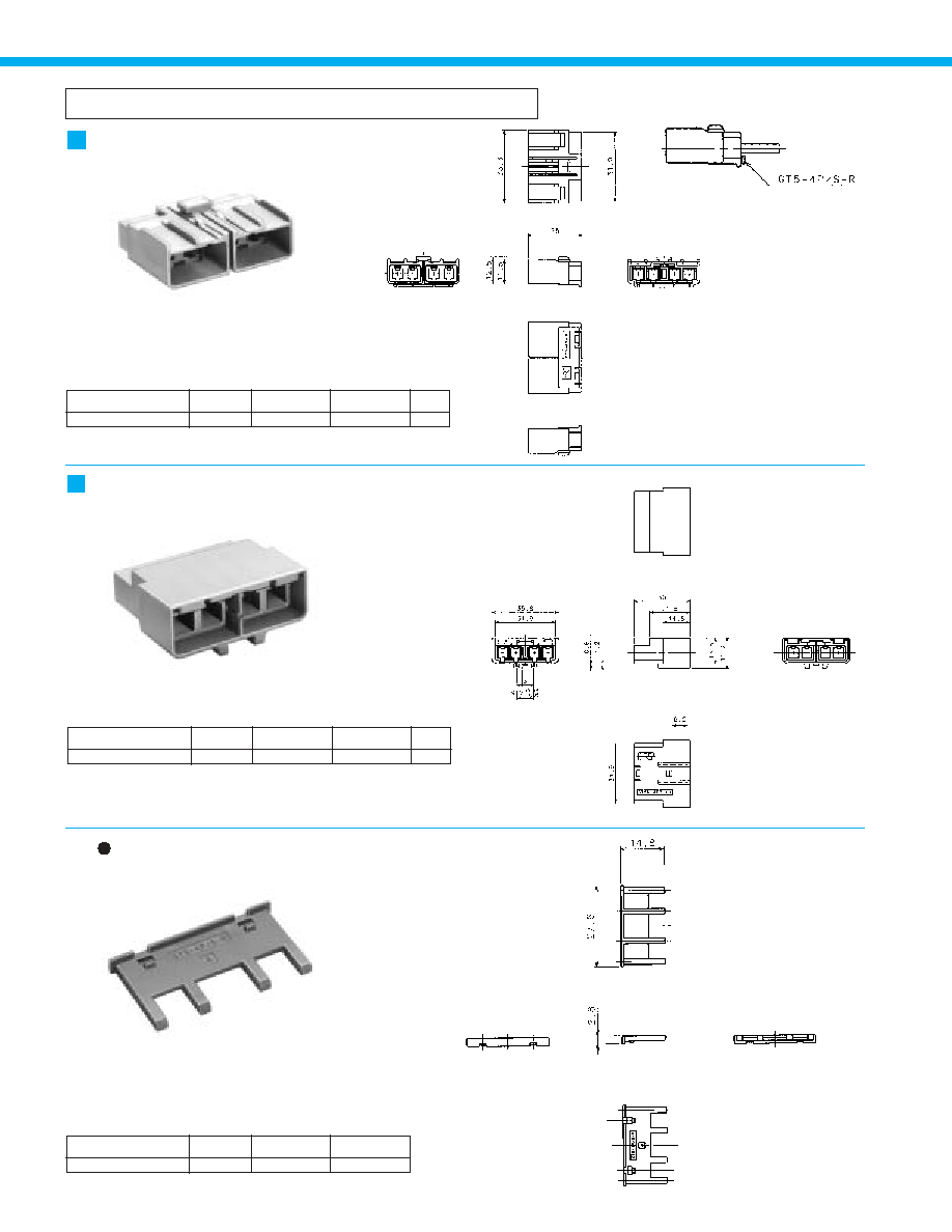
F Connectors
Two-position type-Each Single-Conductor coaxial cable
Figure q
Figure w
Figure e
Figure r
Housing
GT5-2S-HU
GT5-2S-HU(A)
GT5-2S-HU(B)
GT5-2S-HU(C)
755-0044-1
755-0059-9
755-0060-8
755-0097-8
Figure q
Figure w
Figure e
Figure r
D2
A2
B2
C2
Part Number
CL No.
Color
Key polarizing
code
USCAR-19
Coding
Note 1: Terminal extraction tool: GT-PO(A)
Note 2: Used with separate retainer (GT-5-2P/S-R).
Light Gray
Brown
Green
Blue
Material
PBT
Shown with inserted retainer.
M Connectors
Housing[Panel Mounted Housing]
Figure q
Figure w
Figure e
Figure r
GT5-2PP-HU
GT5-2PP-HU(A)
GT5-2PP-HU(B)
GT5-2PP-HU(C)
755-0045-4
755-0063-6
755-0064-9
-
Part Number
CL No.
Key polarizing
code
Note: Used with separate retainer (GT-5-2P/S-R).
Coding D2 at USCAR-19 is GT5-2PP-HU.
Figure q
Figure w
Figure e
Figure r
Color
Light Gray
Brown
Green
Blue
Tin plating
B
Recommended Mounting Bracket dimensions.
B
Fully mated connector assemblies
Part
Housing
Ground terminal
Material
PBT
Phosphor bronze
Finish
-
Tin plating
B
Keying Configurations
B
Keying Configurations
35
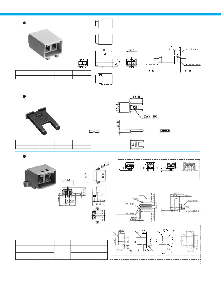
Figure q
Figure w
Figure e
Figure r
GT5-2P-DS (D)
Recommended Panel Cut-out
GT5-2P-DS (A)
GT5-2P-DS (B)
GT5-2P-DS (C)
Housing
Retainer � 2 position (Used with GT5-2S-HU, GT5-2PP-HU,
and GT5N-2PP-HU)
Housing
GT5N-2PP-HU
755-0055-8
Part Number
CL No.
Color
Note 1:Terminal extraction tool: GT-PO(A)
Note 2: Used with separate retainer (GT-5-2P/S-R).
Light gray
Material
PBT
B
Diagram of Mated Connector in Use
GT5-2P/S-R
755-0046-7
Part Number
CL No.
Color
Dark gray
Material
PBT
GT5-2P-DS
GT5-2P-DS(A)
GT5-2P-DS(B)
GT5-2P-DS(C)
755-0043-9
755-0061-0
755-0062-3
-
Figure q
Figure w
Figure e
Figure r
D2
A2
B2
C2
Part Number
CL No.
Color
Key polarizing
code
USCAR-19
Coding
Note: Use mounting screws of M3 with nominal diameter 3L-6 (for a
board thickness of 1.6 mm).
Coding D2 at USCAR-19 is GT5-2P-DS.
Light Gray
Brown
Green
Blue
Material
PBT
B
Recommended Board Mounting
Pattern
B
Mounted and fully mated
connector assemblies
For outer conductor
For inner conductor
Panel
B
Keying Configurations
Board Thickness : 1.6mm
36

Power Supply Terminals
F Connector Terminals
M Connector Terminals
GT7-2022SCF
GT7A-2022SCF
757-0001-1
757-0003-7
#20 to 22
#20 to 22
Part Number
CL No.
5,000
3,000
Material
Finish
Conductor Size (AWG)
Outer
Diameter
Packaging
Note 1: Sold by the reel. (See above table for number of Packaging.)
Note 2: This component is used only with applicable HRS housings.
Copper alloy
Tin plating
1.4 to 2.4mm
2.6 to 3.1mm
GT7-2022PCF
GT7A-2022PCF
757-0002-4
757-0004-0
Part Number
CL No.
5,000
3,000
Material
Finish
Outer
Diameter
Packaging
Note 1: Sold by the reel. (See above table for number of Packaging.)
Note 2: This component is used only with applicable HRS housings.
Brass
Tin plating
1.4 to 2.4mm
2.6 to 3.1mm
( For use with combination type assemblies:
GT5-2/1S-HU, GT5-2/1P-DS, GT5-2/1PP-HU, GT5N-2/1PP-HU)
37

Combinaton Type (Two Single-Conductor Coaxial Cables + One Power contact)
F Connectors
Housing
GT5-2/1S-HU
755-0009-0
Part Number
CL No.
Color
Note 1:Terminal extraction tool: GT-PO(A)
Note 2: Used with separate retainer (GT5-2/1S-R).
Light gray
Material
PBT
B
Shown with inserted retainer.
Retainer (exclusively for GT5-2/1S-HU)
GT5-2/1S-R
755-0003-4
Part Number
CL No.
Color
Dark gray
Material
PBT
M Connectors
Connector assembly, Printed
Circuit Board mounting
GT5-2/1P-DS
755-0014-0
Part Number
CL No.
Note: Use mounting screws of M3 with nominal diameter 3L-6 (for a board thickness of 1.6 mm).
Housing
0. 64x1.1 Terminal
Insulator
Outer terminal
Tub terminal for DS 070
PBT
Brass
PBT
Phosphor bronze
Brass
Color: Light gray
Tin plating
Dark gray
Tin plating
Tin plating
Part
Material
Finish
B
Recommended Board Mounting Pattern
Thickness :
1.6mm
For power supply
For inner conductor
For outside conductor
Retainer
Board
B
Recommended Panel Cut-out
38
M Connectors
GT5-2 / 1PP-R
Housing - with External Ground
Part Number
GT5-2/1PP-HU
CL No.
755-0008-8
Part
Material
Finish
Housing
Ground terminal
PBT
Phosphor bronze
Color: Light gray
Tin plating
Note 1: Terminal extraction tool: GT-PO(A)
Note 2: Used with separate retainer (GT5-2/1PP-R ).
Mounting bracket
attachment side
Outside ground connection
B
Shown with inserted retainer.
Tin plating finish
min.
Part Number
GT5N-2/1PP-HU
CL No.
755-0013-8
Material
Color
PBT
Light gray
Note 1: Terminal extraction tool: GT-PO(A)
Note 2: Used with separate retainer GT5-2/1PP-R and mounting bracket GT-BK or GT-BK (01).
Retainer (Used with GT5N-2/1PP-HU and GT5-2/1PP-HU)
Part Number
GT5-2/1PP-R
CL No.
755-0010-0
Material
Color
PBT
Dark gray
B
Recommended Mounting Bracket Dimensions
Retainer
Housing - without External Ground
39
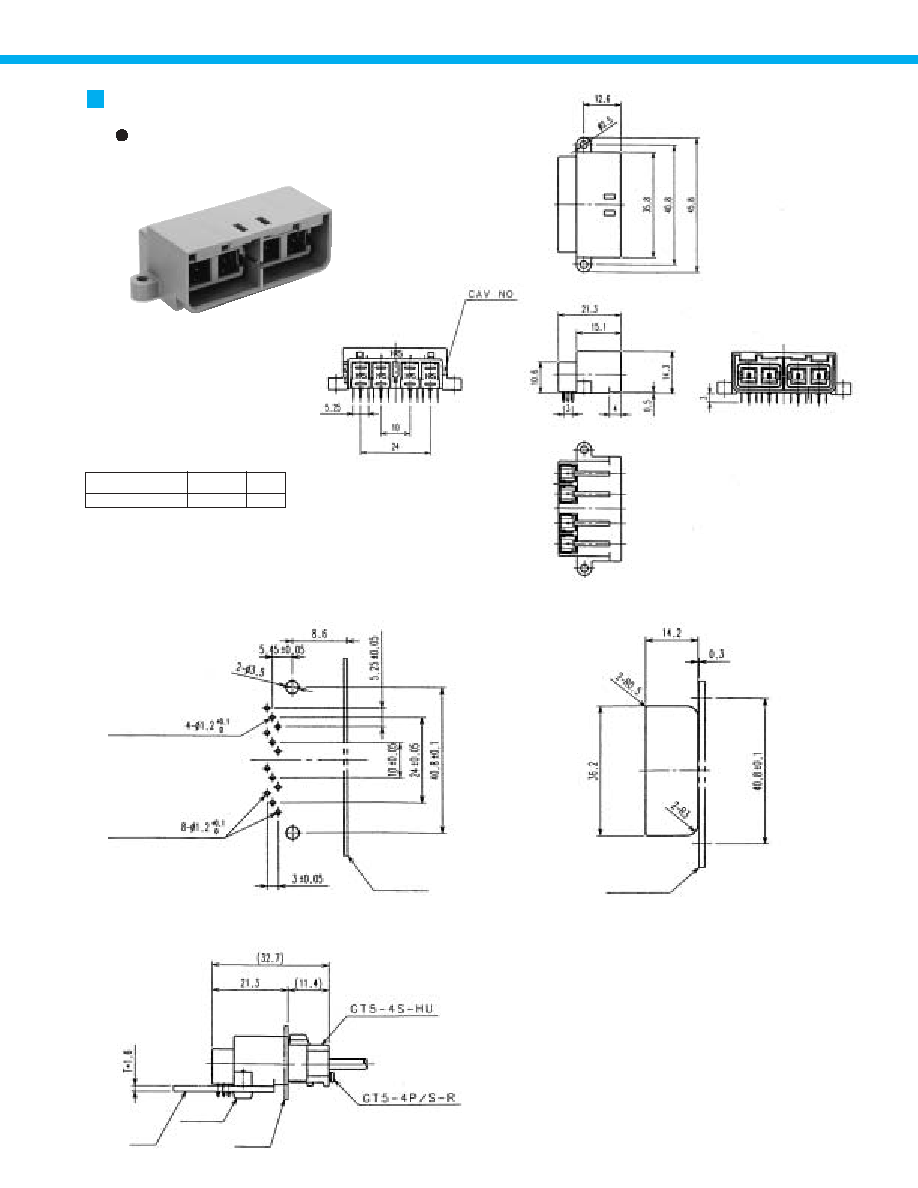
F Connectors
Part Number
GT5-4S-HU
CL No.
755-0056-0
Material
Color
USCAR-19
Coding
PBT
Light gray
D4
Note: Used with separate retainer (GT-5-4P/S-R).
M Connectors
Part Number
GT5N-4PP-HU
CL No.
755-0057-3
Material
Color
USCAR-19
Coding
PBT
Light gray
D4
Note 1: The product should be used with a low-force insertion/withdrawal M connector
terminal.
Note 2: Used with separate retainer GT-5-4P/S-R.
Retainer (Used with GT5-4S-HU and GT5N-4PP-HU)
Part Number
GT5-4P/S-R
CL No.
755-0058-6
Material
Color
PBT
Dark gray
4-Position � Single conductor Coaxial cable
B
Shown with inserted retainer.
40
M Connectors
B
Recommended Board Mounting Pattern
B
Recommended Panel Cut-out
B
Recommended Board and Panel installation
GT5-4P-DS
755-0087-4
D4
Part Number
CL No.
USCAR-19
Coding
For inner conductors
For outer conductors
PCB Board Outline
Panel
Board
Connector assembly, Printed Circuit
Board Mounting
Panel Outline
M3 Screw
41
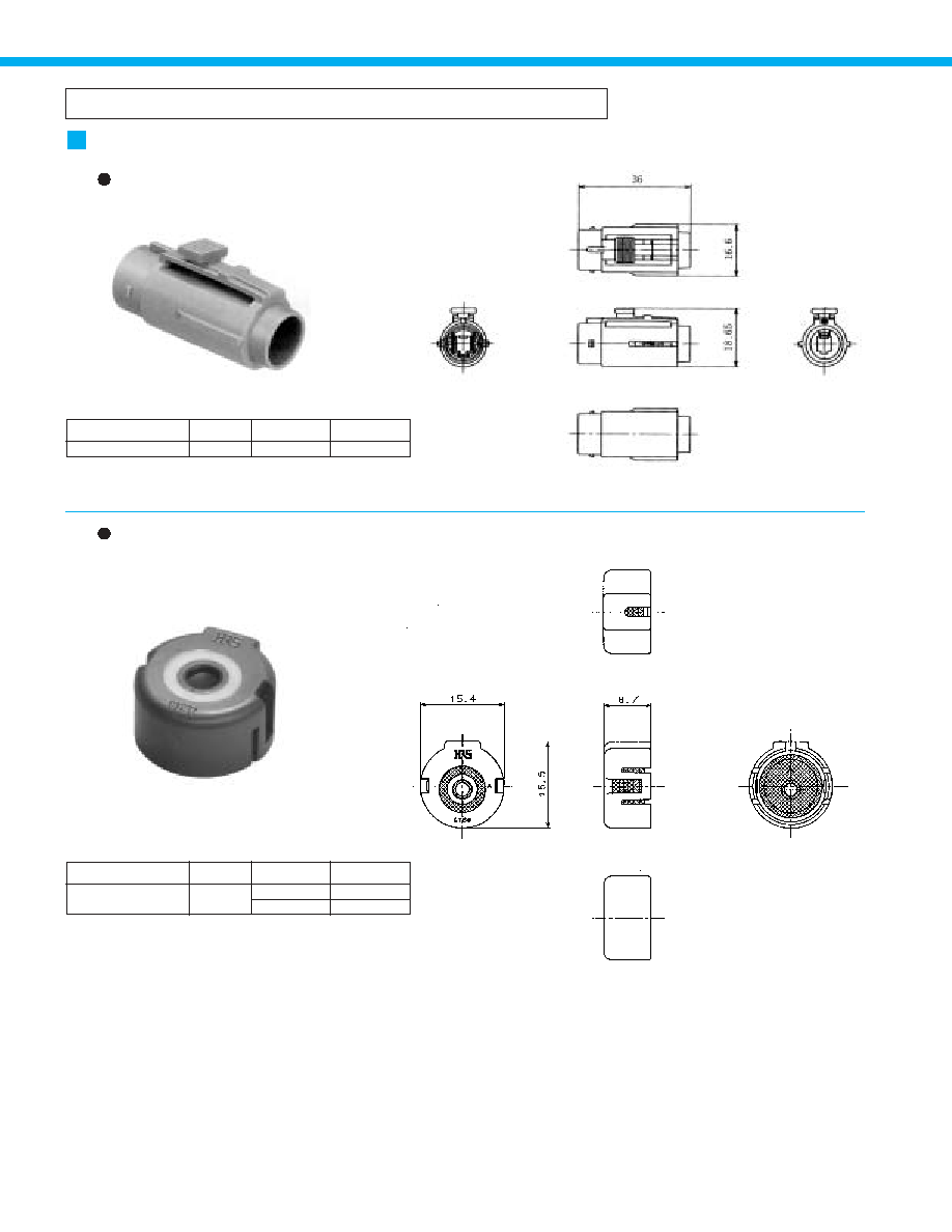
Single Conductor Coaxial Cable - Waterproof Type
F Connectors
Housing
Part Number
GT5W-1S-HU
CL No.
755-0027-2
Materia
l
Color
PBT
Light gray
Note: Specific retainer is determined by the type of the cable used.
Note: Outer diameter of the cable must be within 2.9 to 3.4 mm. Consult nearest HRS
representative for other diameters.
Retainer (Used with GT5W-1P-HU, GT5JW-1PP-HU,
GT5W-1S-HU and GT5W-1P-HU)
Part Number
GT5W-1P/S-R
CL No.
755-0028-5
Materia
l
Color
PBT
Silicon rubber Compound
Dark gray
Dark gray
42

M Connectors
Housing
Part Number
GT5W-1P-HU
CL No.
755-0026-0
Part
Material
Color
Housing
Connector seal
PBT
Silicon rubber
Light gray
White
Note: Use correct retainer.
GT5W-1PP-HU
GT5JW-1PP-HU
755-0070-1
755-0069-2
Part Number
CL No.
B
1.3
3.0
A
1.5
3.2
Part
Housing
Connector seal
Material
PBT
Silicon rubber Compound
Color
Light gray
White
B
Mounted and fully mated connector assemblies
B
Recommended Bracket Dimensions
Housing - Bracket Mounting
43

G Terminals
For Direct Coaxial Cable Termination
1.5D-2V or equivalent
Part Number
GTB-1.6CF
CL No.
755-0049-5
Material
Finish
Packaging
Brass
Tin plating
1,500 pcs. Per reel
Part Number
G-1.6PCF
CL No.
755-0029-8
Material
Finish
Packaging
Brass
Tin plating
1,500 pcs. Per reel
B
Board Termination Pattern
B
Completed Termination cross section
B
Board Termination Pattern
B
Completed Termination cross section
B
Board Termination Pattern
B
Completed Termination cross section
Heat-shrink tubing
Pre-solder
1.5D-2V or equivalent
1.5D-2V or equivalent
Heat-shrink tubing
Lands
Lands
Part Number
GTA-1.6CF
CL No.
755-0032-2
Material
Finish
Packaging
Brass
Tin plating
1,500 pcs. Per reel
44

For Direct Coaxial Cable Termination
Raised point of contact
For Mid-Cable Termination
Part Number
GT-1.6PG-C
CL No.
755-0031-0
Material
Finish
Packaging
Brass
Tin plating
1
B
Recommended Panel Cut-out
B
Attachment Diagram
Setscrew (M2.5)
For use with coaxial cables 2.9
to 3.4 mm. outside diameter.
Panel
B
Recommended Board
Termination Pattern
B
Completed Termination Cross Section
B
Recommended Board
Termination Pattern
B
Recommended Completed Termination cross
section
Part Number
GTA-0.7CF
CL No.
755-0074-2
Material
Finish
Packaging
Brass
Tin plating
1,500 pcs. Per reel
Part Number
GTB-0.7CF
CL No.
755-0075-5
Material
Finish
Packaging
Brass
Tin plating
1,500 pcs. Per reel
Pre-solder
Lands
Lands
45

Bottom Shield cover
Part Number
GT5-1P/S-CSB
CL No.
755-0048-2
Material
Finish
Brass
Tin plating
Mounted Condition Installed
Mounted Condition Installed
GT5C-1P-CSB
755-0088-7
Part Number
CL No.
Top Shield covers
For Improved Electronic Noise Compatibility
46
Automatic crimping machine
* Crimp height setting tables are available for each cable type. Please contact your
nearest Hirose Electric account representative.
Different cables will require different crimp height settings.
B
Termination Tools
User's manuals are available. Please ask your Hirose Electric account representative.
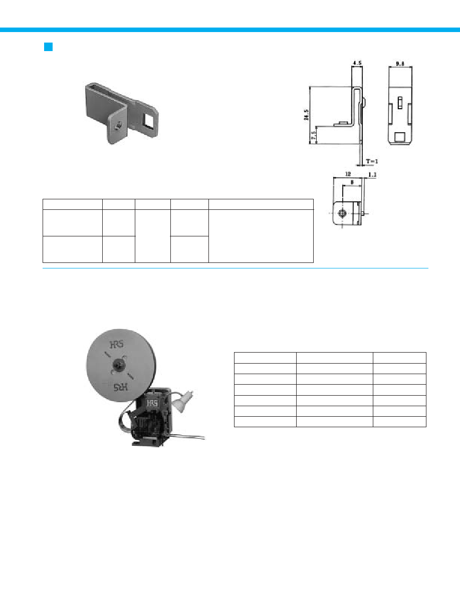
GT-BK
GT-BK (01)
Panel Mounting In-line Bracket
Item
Specification
Stroke length
Number of strokes
Weight
Motor
Crimping speed
Specification
1.5tons
30mm
200spm(50Hz)
75kg
0.2kW
2000 to 4000pcs. Per day
Remarks
200spm(60Hz)
AC100V
Specifications
Part Number
GT-BK
GT-BK(01)
CL No.
751-0039-6
751-0039-6-01
Material
Finish
Used with connectors
SPCC
Tin plating
Zinc plating
GT5-1PP-HU(A),GT5-1PP-HU(B),GT5-1PP-
HU(C),GT5-1PP-HU(D),GT5-1PP-HU(E),GT5-1PP-
HU(F),GT5-1PP-HU(G),GT5-1PP-HU(H),GT5-
2/1PP-HU,GT5-2/1PP-HU(A),GT5-2/1PP-HU(A)
Part Number CM-105
47