Interface Portions and In-line Portions of the Various Units and Devices
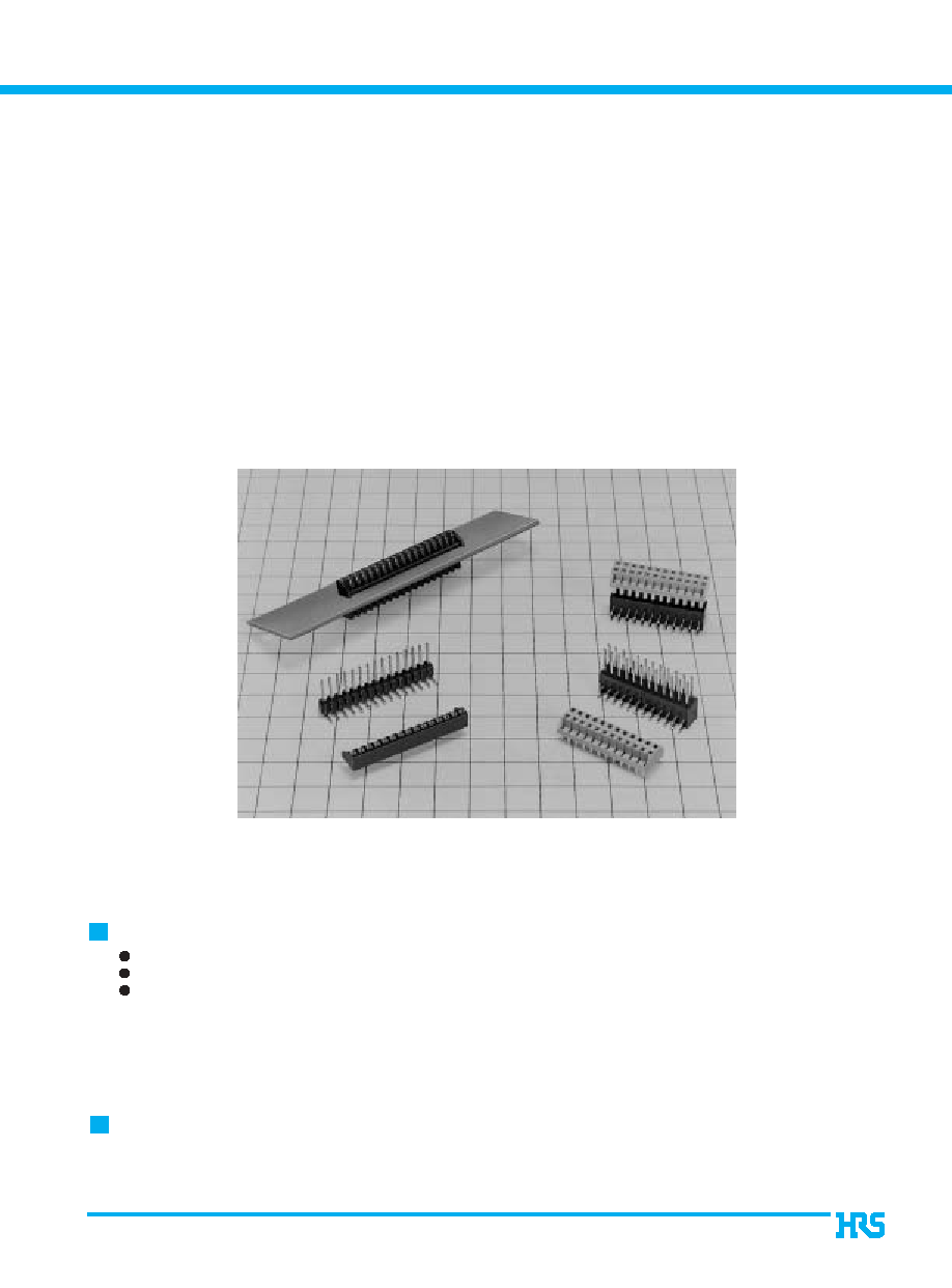
GT9 Series
Developed for Equipment
Exposed to Harsh Environmental Conditions
<
12 Pos., 15 Pos., 16 Pos., 18 Pos., 19 Pos., and 25 Pos.
>
2003.7
Features
Bottom entry type
High-pressure type with dimple processing at contact portion
Flux prevention processing specification also available.* (Specification 05)
* Flux prevention processing: The hole connector is immersed in a flux prevention processing liquid and the
surface is coated to prevent flux wicking.
Custom orders of other numbers of Pos. can be accommodated.
Applications
Automotive equipment, IPM, and IGBT.

Flux prevention processing
Flux prevention processing, with locator, cost effective item
Flux prevention processing, with locator
Flux prevention processing
Flux prevention processing, with locator, cost effective item
Flux prevention processing, with locator
Flux prevention processing
Flux prevention processing, with locator, cost effective item
Flux prevention processing, with locator
Flux prevention processing
Flux prevention processing, with locator, cost effective item
Flux prevention processing, with locator
GT9P-12P-2.54DSA
GT9P-12P-2.54DSA (05)
GT9P-12P-2.54DSA (12)
GT9P-12P-2.54DSA (13)
GT9P-16P-2.54DSA
GT9P-16P-2.54DSA (05)
GT9P-16P-2.54DSA (12)
GT9P-16P-2.54DSA (13)
GT9P-19P-2.54DSA
GT9P-19P-2.54DSA (05)
GT9P-19P-2.54DSA (12)
GT9P-19P-2.54DSA (13)
GT9P-25P-2.54DSA
GT9P-25P-2.54DSA (05)
GT9P-25P-2.54DSA (12)
GT9P-25P-2.54DSA (13)
Part Number
CL No.
Remarks
12
30.48
30.48
30.48
30.48
16
40.64
40.64
40.64
40.64
19
48.26
48.26
48.26
48.26
25
759-0014-6 00
759-0014-6 05
759-0014-6 12
759-0014-6 13
759-0015-9 00
759-0015-9 05
759-0015-9 12
759-0015-9 13
759-0016-1 00
759-0016-1 05
759-0016-1 12
759-0016-1 13
759-0010-5 00
759-0010-5 05
759-0010-5 12
759-0010-5 13
63.50
63.50
63.50
63.50
GT9-12P-2.54DS
GT9-12P-2.54DS (05)
GT9-15P-2.54DS
GT9-15P-2.54DS (05)
GT9-18P-2.54DS
GT9-18P-2.54DS (05)
GT9-25P-2.54DS
GT9-25P-2.54DS (05)
Part Number
CL No.
Remarks
12
30.48
15
38.1
0
18
45.72
25
63.5
0
Flux prevention finish
Flux prevention finish
Flux prevention finish
Flux prevention finish
759-0012-0
-05
759-0012-0-05
759-0004-2
-05
759-0004-2-05
759-0005-5
-05
759-0005-5-05
759-0007-0
-05
759-0007-0-05
Single-Row Type
Item
Material
Finish
Housing
PBT
Color: Black
Terminal
Brass
Tin plating
Item
Material
Finish
Housing
PBT
Color: Black
Terminal
Brass
Tin plating
Item
Material
Finish
Housing
PA (Note)
Color: Black
Terminal
Phosphor bronze
Tin plating
Note: The material is PBT for the 12-pos. type only.
GT9-12S-2.54DSA
GT9-12S-2.54DSA (05)
GT9-15S-2.54DSA
GT9-15S-2.54DSA (05)
GT9-16S-2.54DSA
GT9-16S-2.54DSA (05)
GT9-18S-2.54DSA
GT9-18S-2.54DSA (05)
GT9-19S-2.54DSA
GT9-19S-2.54DSA (05)
GT9-25S-2.54DSA
GT9-25S-2.54DSA (05)
12
15
16
18
19
25
30.48
38.1
0
40.64
45.72
48.26
63.5
0
Part Number
Number of
positions
A
dimension
Remarks
CL No.
759-0011-8
-05
759-0011-8-05
759-0001-4
-05
759-0001-4-05
759-0008-3
-05
759-0008-3-05
759-0002-7
-05
759-0002-7-05
759-0009-6
-05
759-0009-6-05
759-0006-8
-05
759-0006-8-05
Flux prevention finish
Flux prevention finish
Flux prevention finish
Flux prevention finish
Flux prevention finish
Flux prevention finish
B
Recommended PCB Mounting Pattern
2
F Connectors
M Connectors
Right-angle Type
Number of
positions
A
dimension
Straight Type
Number of
positions
A
dimension
Production
Lot No. Marking

5
2.8
0.74
10.16
7.16
7.16
7.16
53.74
5.2
P=
2.54
3
3
3
3
3
2.54
14.1
14.1
14.1
4.45
2.54 ±0.05
14.1 ±0.05
14.1 ±0.05
14.1 ±0.05
3 ±0.05
3 ±0.05
3 ±0.05
3 ±0.05
3 ±0.05
43.57 ±0.1
19-
1.2
+0.1
0
19-
0.9
+0.1
0
4-
3.2
+0.1
-0.07
2.54
±0.05
14.6
±0.1
5-Row Type
B
Recommended PCB Mounting Pattern
Part Number
CL No.
Item
Material
Finish
Housing
PBT
Color: Black
GT9H-19S-2.54DSA (01)
759-0023-7-01
DSA Terminal
Phosphor bronze
Contact area: Gold plating
Termination area: Tin plating
F Connectors

