27
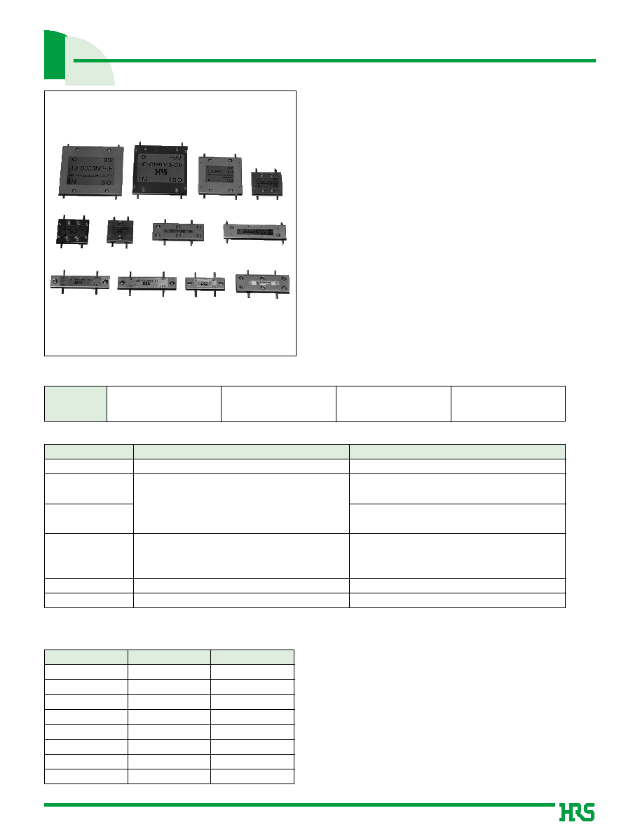
3 dB 90∞ Card Couplers
HD-M Series
s
Features
1.High Performance
The high frequency characteristics feature.
Extremely low loss and a high degree of matching.
2.Power Uniform Distribution and
90
∞
Phase Difference Type
This is a one input, two output (or two input, one
output) power uniform distribution type having a
90
∞
phase difference between the two outputs (or
two inputs).
3.Miniature and Lightweight
Corrosion-resistant aluminum is used for the cover
and the Hirose Electric original pattern design,
which uses a stripline triplate method, enables the
couplers to be extremely small and lightweight.
4.Equipped with Tabs
Tabs permit direct mounting to surface circuits.
5.High Power Type
This type can be used with up to 100 W of power.
s
Product Specifications
Note: The frequency range and the maximum input power will differ depending on the products.
q
The test method conforms to MIL-STD-202.
s
Materials
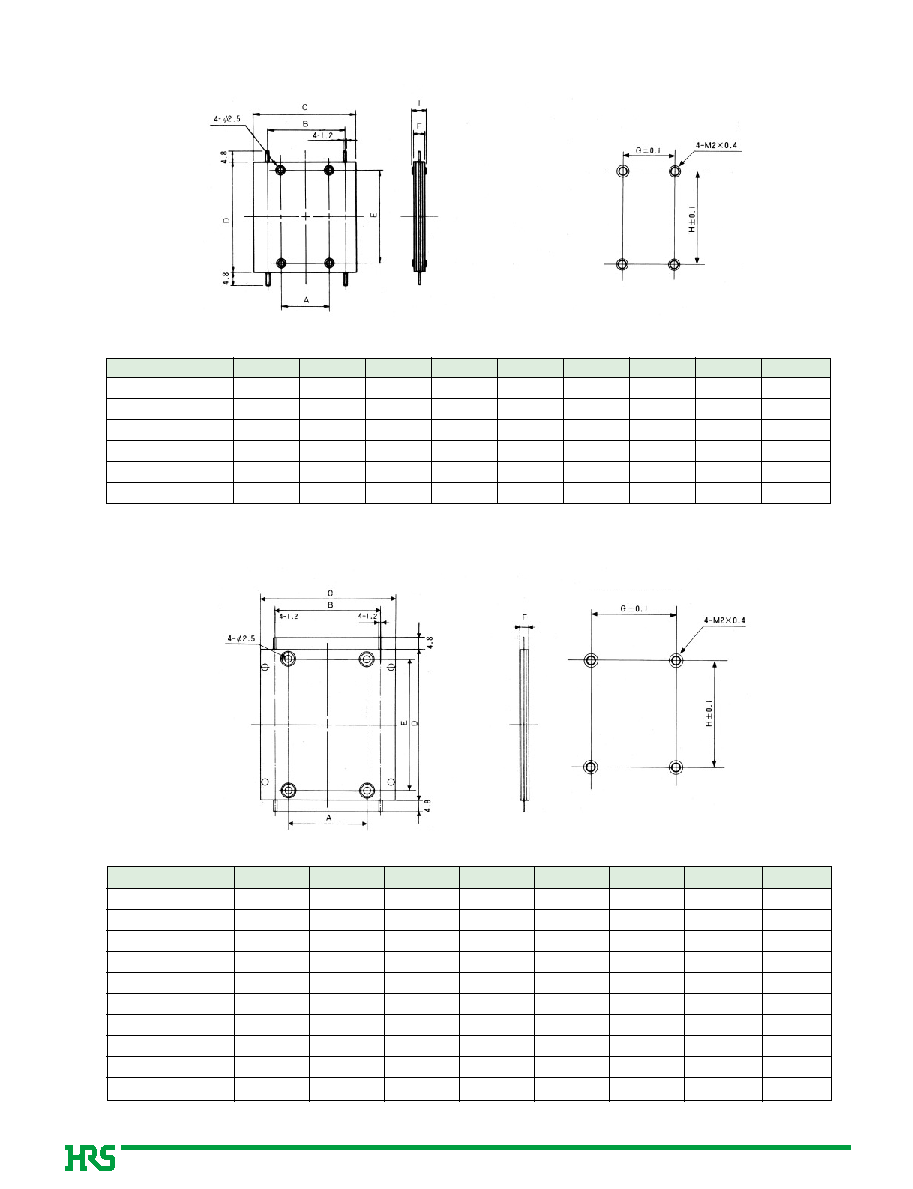
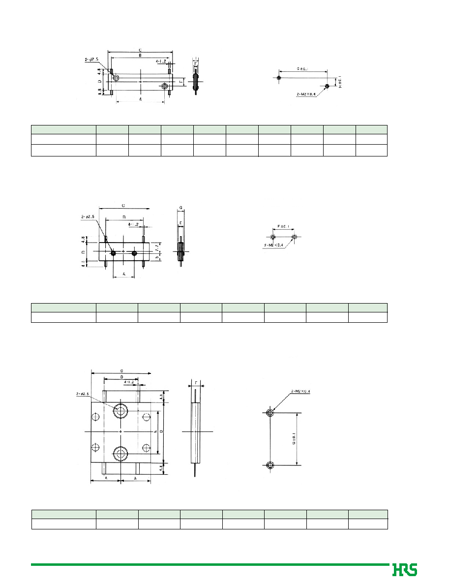
Ratings
Frequency range (Note)
Characteristic impedance
Maximum Input Power (Note)
30 to 6400 MHz
50
ohms
50 to 100 W
Operating temperature range
Operating relative humidity
-10
Á
to +65
Á
95
%
Max.
Item
Standard
Conditions
Part
Material
Finish
Cover (A)
Stainless steel
---------
Cover (B)
Aluminum
Conductive white Alumite
Board
Dielectric
Gold plating
Rivets
Aluminum
---------
Eyelet
Brass
Nickel plating
Tabs
Phosphor bronze
Gold plating
Cover (A)
Stainless steel
---------
Cover (B)
Stainless steel
---------
1.Insulation resistance 500M
ohms
min
100 V DC
2.Vibration
Frequency of 10 to 2000 Hz, overall amplitude of 1.52 mm,
acceleration of 98 m/s
2
for 2 hours in each of 3 directions
3.Shock
Acceleration of 980 m/s
2
, sine half-wave waveform,
3 cycles in each of the 3 axis
Temperature : -55
Á
°
+5
Á
to +35
Á
°
+85
Á
°
+5
Á
to +35
Á
4.Temperature cycle No damage, cracks, or parts dislocation
Time : 30
°
15 max.
°
30
°
15 max. (Minutes)
200 cycles
5.Corrosion resistance No serious corrosion
Exposed to 20% salt water solution for 48 hours
6.Hydrogen sulfide gas No damage, cracks, or parts dislocation
Exposed to 10% potassium sulfide solution for 100 hours
No electrical discontinuity of 1
µ
s or more
No damage, cracks, or parts dislocation
HD-0053M3-IH
HD-0195M3-DH
HD-0195M3-DH-1
HD-0900M3-CH-1
HD-0620M3-EH
HD-1700M3-FH
HD-3900M3-BH
HD-0313M3-FH
HD-2100M3-CH
HD-1800M3-CH
HD-3200M3-BH
HD-6150M3-AH