A56
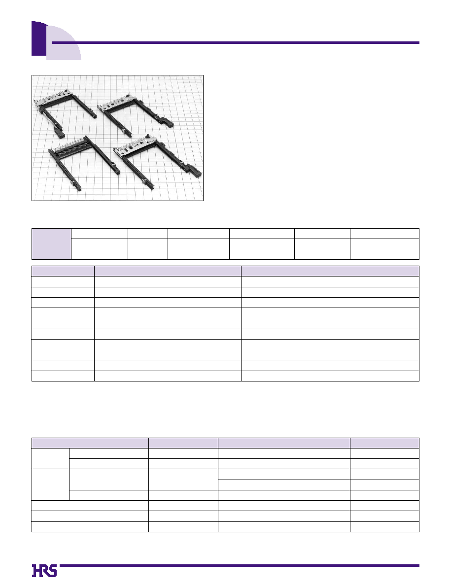
Single Slot Connector for PC Card Type III
IC7 Series
4.Vibration
5.Humidity (Steady state)
7.Durability (insertion/ withdrawal)
8.Resistance to soldering heat
6.Temperature cycle
s
Features
1. PC Card Standard compliant:
Type I, type II and type III cards are covered. Terminals for
grounding are provided.
2. Space saving and Lightweight
Connector height is minimized to 5.4mm, and weight is 12.5g.
3. Eject mechanism
Hirose's unique ejection mechanism provides an higher degree of
card ejection over existing products.
s
Product Specifications
500 V DC
500 V AC / 1 minute
1mA
Frequency: 10 to 2000 Hz, full amplitude of 1.52 mm or
acceleration of 147m/s
2
, 4 hours in each of the 3 directions
96 hours at temperature of 40
Á
and humidity of 90% to 95%
Temperature: -55
Á ©
+15
Á
to +35
Á ©
+85
Á ©
+15
Á
to +35
Á
Time: 30
©
5 max.
©
30
©
5 max. (Minutes) 5 cycles
10000 cycles at 400 to 600 cycles per hous
Manual soldering: 300
Á
for 3 seconds
1000 M ohms min.
No flashover or insulation breakdown
40 m ohms max. (Initial value)
No electrical discontinuity of 100ns or more
Insulation resistance: 100 M ohms min.
No damage, cracks, or parts looseness
Contact resistance: 20 m ohms max. from initial value
No deformation of the insulator parts affecting performance
1.Insulation resistance
2.Withstanding voltage
3.Contact resistance
Rating
Current rating
0.5 A
Voltage rating
125V AC
Operating temperature range -55
Á
to +85
Á
(Note 1)
Operating humidity range Relative humidity 95% max.
(No condensation)
Storage temperature range -40
Á
to +70
Á
(Note 2)
Storage humidity range Relative humidity 40% to 70%
Item
Specification
Conditions
Note 1: Includes temperature rise caused by current flow.
Note 2: The term "storage" refers to products stored for long period of time prior to mounting and use. Operating Temperature Range and Humidity
range covers non- conducting condition of installed connectors in storage, shipment or during transportation.
s
Material
Part
Insulator
Contact
Material
Connector
Eject Button
Connector
Eject metal fitting
Locking pins
Nuts
Terminals for grounding
Finish
PBT
PA
Brass
Phosphor bronze
Stainless steel
Phosphor bronze
Steel
Color: Black
Color: Black
Contact area: gold plating
Lead area: Solder plating
Gold plating
----------
Solder plating
Nickel plating
Remarks
UL94V-0
UL94V-0
----------
----------
----------
----------
----------
----------
A59
s
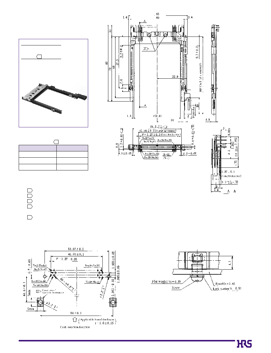
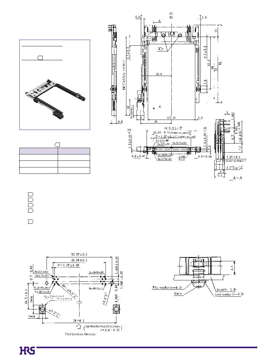
Single Slot Connector
q
Right Eject Button
q
Standard type, Reverse type
Standard
IC7-68PD-1.27DS-EJR
CL640-0401-0
Reverse
IC7-68PDR-1.27DS-EJR
CL640-0402-2
Contact Length
Contact No.
5.0
0
±
0.1
3.5
0
±
0.1
4.25
±
0.1
1, 17, 34, 35, 51, 68
36, 67
Other than above
Table 1
4
1
B
PCB mounting pattern
B
Example of Screw Fastening (Recommendation)
Note
The contacts length is indicated in Table 1.
The applicable range of indicated dimensions (54.2 , 3.5 ) are taken as 10mm from the bottom.
The terminal for grounding should be securely fasted from the bottom surface of the board using a screw (M2
0.4), flat washer and lock washer.
Pay attention to the Contact No. since the reverse type is marked "R". See the numbers in parentheses ( ) for the Contact No. of the
reverse type.
The guide groove dimensions of the reverse type are left-right reversed.
1
2
3
4
5
+0.1
- 0.05
+0.1
- 0.05
A60
s
Single Slot Connector
q
Left Eject Button
q
Standard type, Reverse type
Standard
IC7-68PD-1.27DS-EJL
CL640-0403-5
Reverse
IC7-68PDR-1.27DS-EJL
CL640-0404-8
Contact Length
Contact No.
5.0
0
±
0.1
3.5
0
±
0.1
4.25
±
0.1
1, 17, 34, 35, 51, 68
36, 67
Other than above
Table 1
4
1
B
PCB mounting pattern
B
Example of Screw Fastening (Recommendation)
Note
The contacts length is indicated in Table 1.
The applicable range of indicated dimensions (54.2 , 3.5 ) are taken as 10mm from the bottom.
The terminal for grounding should be securely fasted from the bottom surface of the board using a screw (M2
0.4), flat washer and lock washer.
Pay attention to the Contact No. since the reverse type is marked "R". See the numbers in parentheses ( ) for the Contact No. of the
reverse type.
The guide groove dimensions of the reverse type are left-right reversed.
1
2
3
4
5
+0.1
- 0.05
+0.1
- 0.05