C39
SIM Card Sockets
ID1A Series
Plecement surface
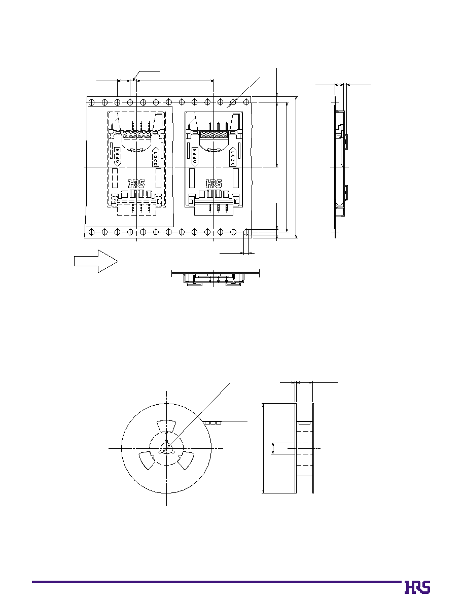
17.4
2.45
30.6
s
Features
1. Suited for Plug-in SIM Cards of the GSM Standard (11.11)
In Europe, SIM card Subscriber Identity Modules are used
for subscriber identification with portable telephone terminals
of the GSM system for which standards have been unified.
The ID1A Series of sockets are suited for use with GSM
standard (11.11) plug-in SIM cards.
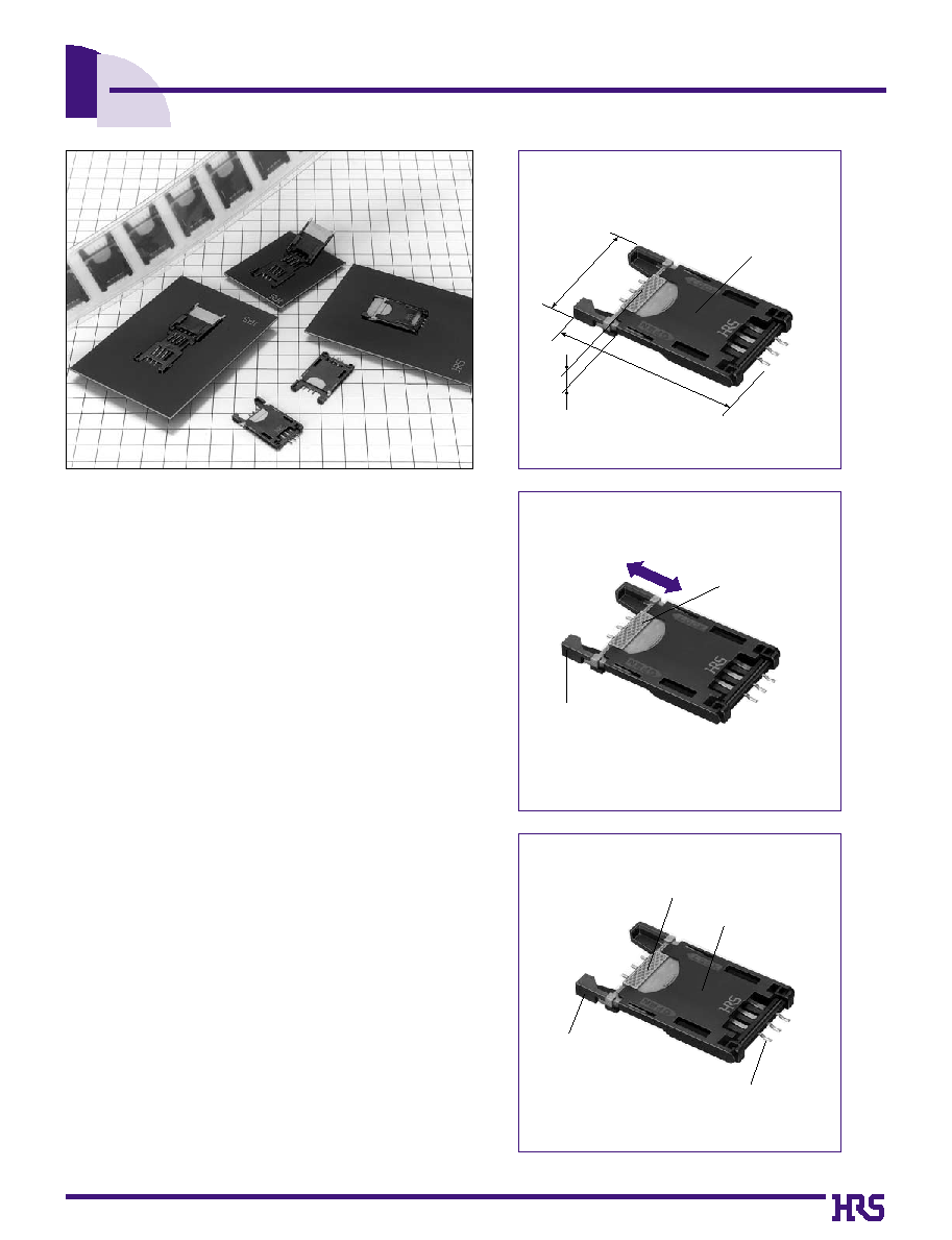
2. Miniature and Thin
These sockets are miniature and thin with a height of 2.45
mm, length of 30.6 mm, and width of 17.4 mm. The weight
has been reduced by 30% compared with our existing
products. (See Photograph (1).)
3. Suited to Automatic Mounting
The board mounting method is of the surface mount
type.In addition to the standard tray packaging
specification, an embossed tape specification suited to
automatic mounting is also available.
4. Prevention of Incorrect Insertion to the Board
A board-positioning boss prevents incorrect insertion to the
board by means of boss position and boss diameter.
5. Slide Lock System
An original lock structure securely holds the SIM card and easy
opening and closing of the card holder is another feature.
(See Photograph (2).)
s
Applications
Portable terminals and equipment that use GSM Standard
(11.11) plug-in SIM cards.
Miniature and Thin
Photograph (1)
Can be locked by
moving the slider.
Upside down insertion
of the SIM card is
prevented through
the establishment
of a polarity.
LOCK
OPEN
Slide Lock System
Photograph (2)
Slider
Card holder
Contacts
Housing
Structure and Names of the Parts
Photograph (3)
C40
s
Product Specifications
Rating
Current rating 1 A
Voltage rating 100 V AC
Operating temperature
-30
ç
to +80
ç
(NOTE 1)
Operating humidity range 40 to 80%
Storage temperature
-10
ç
to +60
ç
(NOTE 2)
Storage humidity 40 to 70% (NOTE 2)
Item
Specification
Conditions
1. Insulation resistance
1000M
ohms
min.
No flashover or insulation breakdown.
40 m
ohms
max.
No electrical discontinuity of 10 µs or
more
Contact resistance 60 m
ohms
max.
Insulation resistance 100 M
ohms
min.
Contact resistance 60 m ohms max.
Insulation resistance 100 M
ohms
min.
Contact resistance of 60 m
ohms
max.
No deformation of components affecting
performance.
100 V DC
500 V AC / 1 minute
100 mA
Frequency: 10 to 55 Hz, single amplitude of 0.75 mm,
2 hours in each of the 3 directions.
96 hours at temperature of 40ç and humidity of
90% to 95%
Temperature: -55
ç
: 30 min. --> 15 to 35
ç
: 5 min.
MAX --> 85
ç
: 30 min --> 15 to 35
ç
: 5 min. MAX) for 5 cycles
5000 cycles
Reflow: At the recommended temperature profile
Manual soldering: 300ç for 3 seconds
2. Withstanding voltage
3. Contact resistance
4. Vibration
5. Humidity (Steady state)
6. Temperature cycle
7. Durability (Insertion/withdrawal)
Insulator
Contacts
Card holder
Slider
Synthetic resin
Color : Black
UL94V-0
UL94V-0
UL94V-0
______
Contact portion: Gold plating
Lead portion: Solder plating
Color : Black
Color : Beige
Phosphor bronze
Synthetic resin
Synthetic resin
8.
Resistance to Soldering heat
Note 1: Includes temperature rise caused by current flow.
Note 2: The term "storage" refers to products stored for long period of time prior to mounting and use. Operating
Temperature Range and Humidity range covers non- conducting condition of installed connectors in storage,
shipment or during transportation.
Part
Material
Finish
Remarks
s
Materials
q
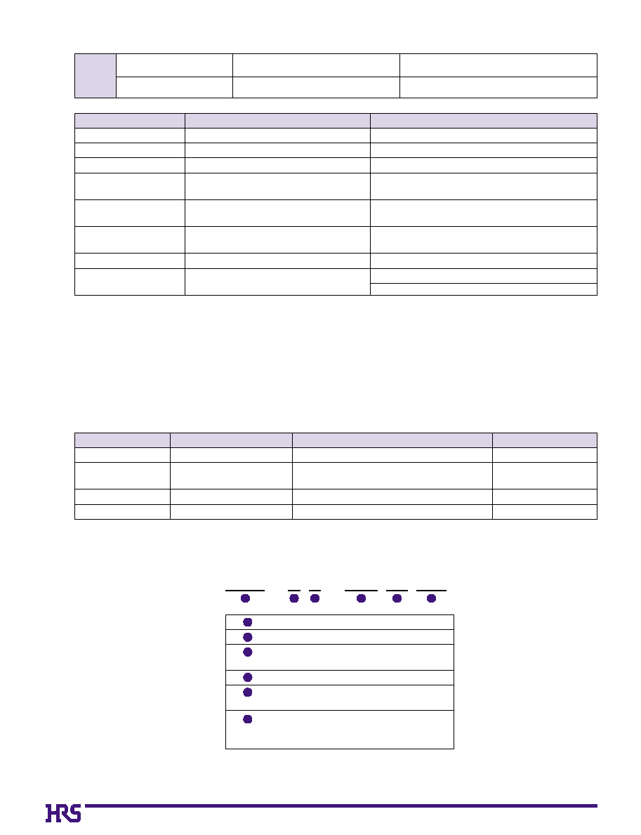
Ordering Information
ID1A - 6 S - 2.54 SF (21)
1
2
3
4
5
6
Series Name: ID1A
Number of contacts: 6
Contact type
S: Socket
Contact pitch: 2.54 mm
Terminal type
SF: SMT type
Packaging type
Blank: Tray packaging
(21): Embossed tape packaging
1
2
4
3
5
6
C41
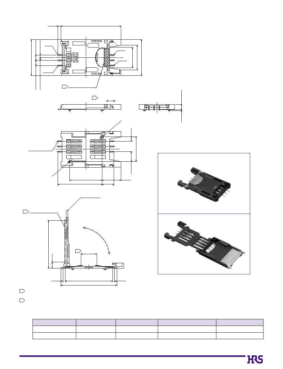
s
Sockets
Protruding portion
0°~180°
1
3
1.18±0.2
17.4±0.3
(0.65)
(2.1)
(4.82)
(9.09)
(5.7)
(21.5)
15.8±0.1
7.62±0.2
(23.15)
(2.9)
(1.1)
(23.02)
27.2±0.2
(1.1)
0.25t±0.05
0.5w±0.05
2.45±0.3
12±0.1
(12)
(10)
2.54±0.2
1.36±0.2
2.54±0.2
17.4±0.3
(1.39)
No.3
No.7
No.5
Contact
No.1
29.2±0.3
Protruding portion
Amount of sliding(1.5)
SIM CARD
(GSM 11.11)
OPEN
LOCK
1
OPEN
LOCK
1
(Ø1.5
)
(Ø1
)
C
L
C
L
C
L
C
L
With the card holder closed
With the card holder open
1
When locking, slide the protruding portion of the slider after the card holder has been closed.
2
The co-planarity at the SMT lead tip portion is 0.1 maximum.
3
indicates a 7.62 ±0.2 center line.
C
L
645-0003-9
645-0003-9-21
NOTE 1: Embossed tape packaged items are sold by the reel with 500 pieces per reel.
ID1A-6S-2.54SF
ID1A-6S-2.54SF(21)
6
6
Tray
Embossed tape (NOTE 1)
______
500 pieces per reel
CL No.
Part Number
Number of Contacts
Packaging type
Number of Pieces
C42
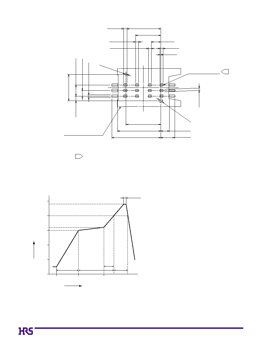
Applicable Conditions
Reflow system: IR reflow
Solder type: Cream type 63 Sn/37 Pb
(Flux component 9 wt%)
Test board: Glass epoxy 85 x 60 x 1 mm
Metal mask thickness: 0.15 mm
Conditions may change and are dependent on type
and thicness of solder.
B
PCB mounting pattern
B
Temperature Profile
15.4±0.1
1.5 Min.
1.3 Min.
1.3 Min.
22.2 Min.
11.5±0.1
15.8±0.05
19.7±0.05
3.9±0.05
6.4 Min.
4.3±0.1
1.1±0.1
2.45±0.05
5.08±0.05
12±0.05
2.1±0.05
1.5 Min.
1.1 Min.
Pattern prohibited area
Connector mounting position
Shaded portions [///] indicate pattern prohibited areas.
1
1
0.4±0.1
Ø1.6
+0.1
0
Ø1.1
+0.1
0
5 s max.
240ç
200ç
160ç
150ç
25ç(60 s)
60 to 90 s
(30 s)
(20 to 30 s)
Soldering time
Preheating time
Time (Seconds)
Start
60
0
50
100
150
200
250
Temperature
(ç)
120