MU
SC
FC
Harsh
Environment
Attenuators
Terminators
55
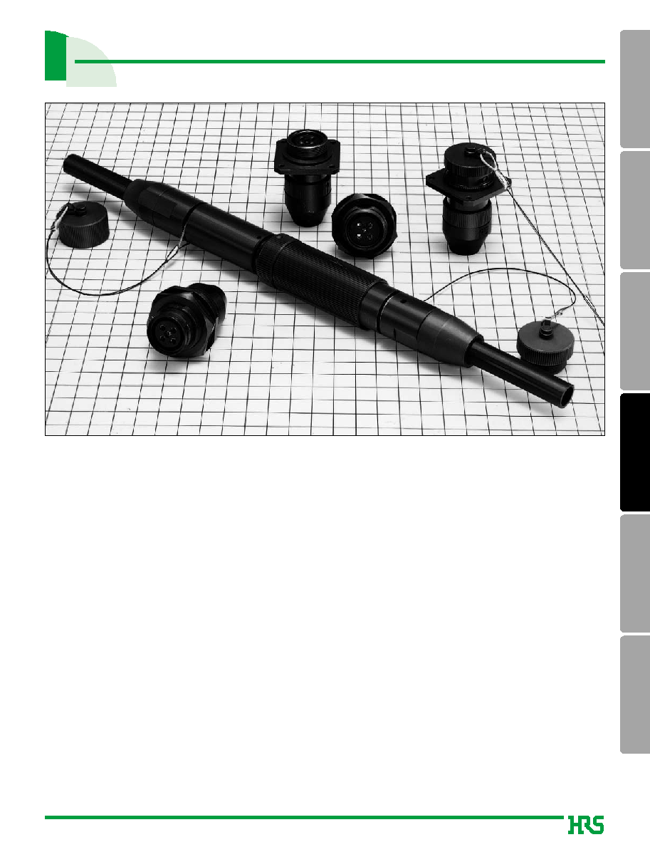
Harsh Environment Fiber Optic Connectors
MF 14 and MF 17 Series
s
Features
1. 2 Fibers (MF14 series), 4 Fibers (MF17 series), or Optical/Electrical Hybrids are available.
6 fibers (MF22 series) available.
2. Incorrect Insertion Prevention.
Guide key (plug) and key slot (receptacle) are designed for prevent incorrect insertion.
3. Plug, receptacle fully mated condition satisfy IP67 wateroof Performance.
4. For more than 10 years, MF series has been designed and installed in many harsh
environmental applications.
Please contact us if you have any requests.
HIROSE will offer excellent solutions to meet your requirements.
s
Applications
Outdoor optical transmission systems, LAN, CATV, ATM, Base station, industrial optical/electric lines.
56
MU
SC
FC
Harsh
Environment
Attenuators
Terminators
Optical
characteristics
Mechanical
characteristics
Environmental
characteristics
Part
Material
Plug and Receptacle Housing
Aluminum alloy
Ferrule case
Synthetic resin
Strain relief
Zinc alloy
Protective cap and clamp
Brass
Rubber boot and O-rings
Synthetic rubber
Screws, springs, and steel wire
Stainless steel
Washer
Brass
Split sleeve
Zirconia or Copper alloy
s
Product Specifications
Ratings
Operating temperature range
Note: Insertion loss herein means only connection loss.
-25°C to +70°C
Storage temperature range
-25°C to +70°C
s
Materials
Item Test
Method
Specifications
Insertion Loss
Wavelength 1310nm (LD)
1.0dB max. (Note)
Durability
100 times
(cycles, mating/un-mating)
Vibration
Shock
Humidity
-10°C to 65°C, humidity: 90% to 96% 10 cycles
(Temperature/ humidity- cycles)
Change of temperature
-40°C to +75°C 42 cycles
Dry heat
960 hours at 85°C
Cold
960 hours at -40°C
Salt Mist
1000 hours in a 5% concentration of salt mist
No visible corrosion.
Waterproof
Inside air pressure 4.90kPa for one minute
No air bubble leakege, IP67
Frequency: 10 to 55 Hz, single amplitude of 0.75 mm,
acceleration of 98.1m/s
2
, 2 hours in each of the 2 axis.
Acceleration of 981 m/s
2
, 6 ms duration, sine half-
wave waveform, 3 cycles in each of the 2 axis.
1) Insertion loss fluctuation after test: 0.3dB max.
2) No visible damage, dislocation of clamp or cable.
1) Insertion loss fluctuation after (test) : 0.3dB max.
2) No visible damage, dislocation of clamp or cable.
s
Important Notice
1. Please ask HIROSE when you assemble the MF connectors for special cables.
Some cables can not be used for the connectors.
2. MF series use SC/PC zirconia ferrules. Please see page 33.
57
MU
SC
FC
Harsh
Environment
Attenuators
Terminators
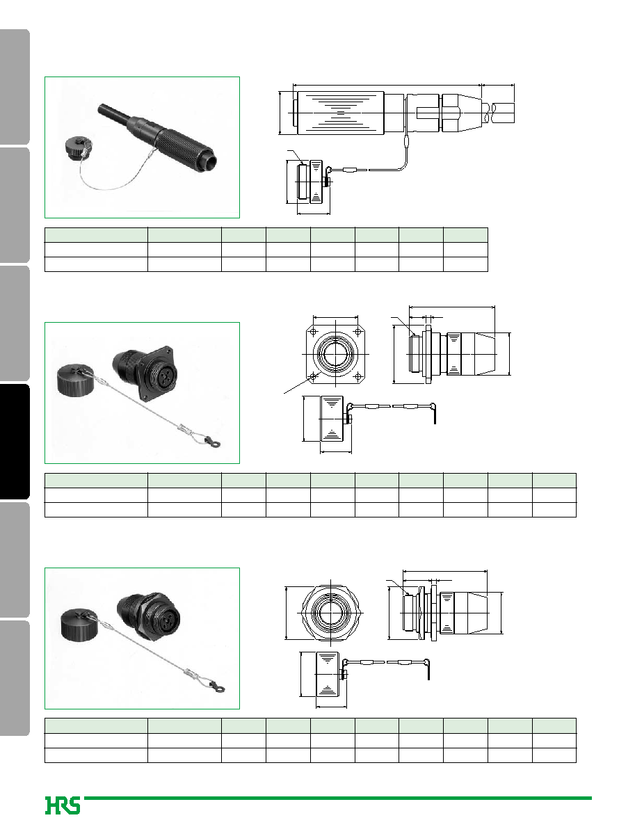
*
indicates cable diameter. 8, 9 and 10mm, diameter cables are appicable.
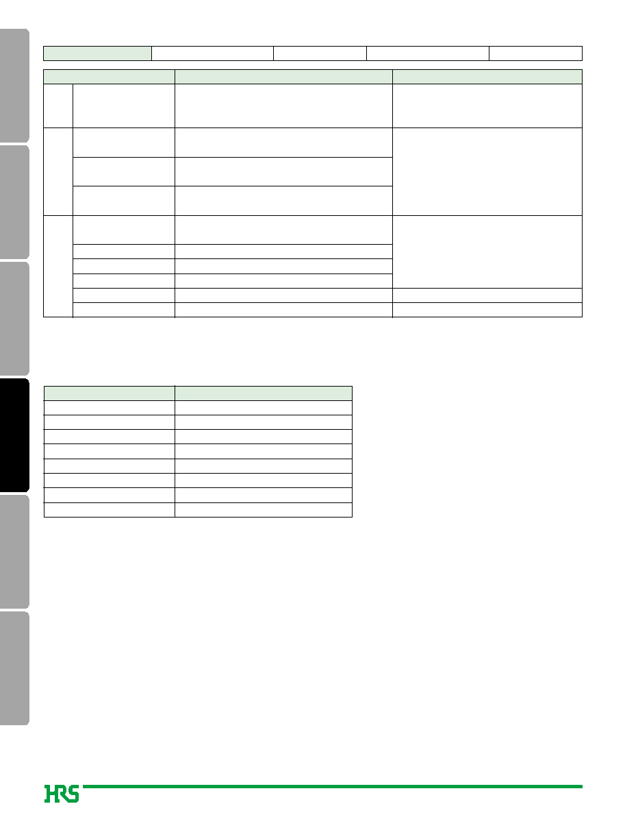
s
Bayonet lock
q
Plug Housing
ØA
ØD
E
B
C
Number of Fibers
Ø
A
B
C
Ø
D
E
2
4
24
27
1
84.7
116.5
69
52
24
27
21
21
Part Number
MF14B-WP
*
S01-0200
MF17B-WP
*
S01-0400
Note: Up to 3 mm cables are applicable.
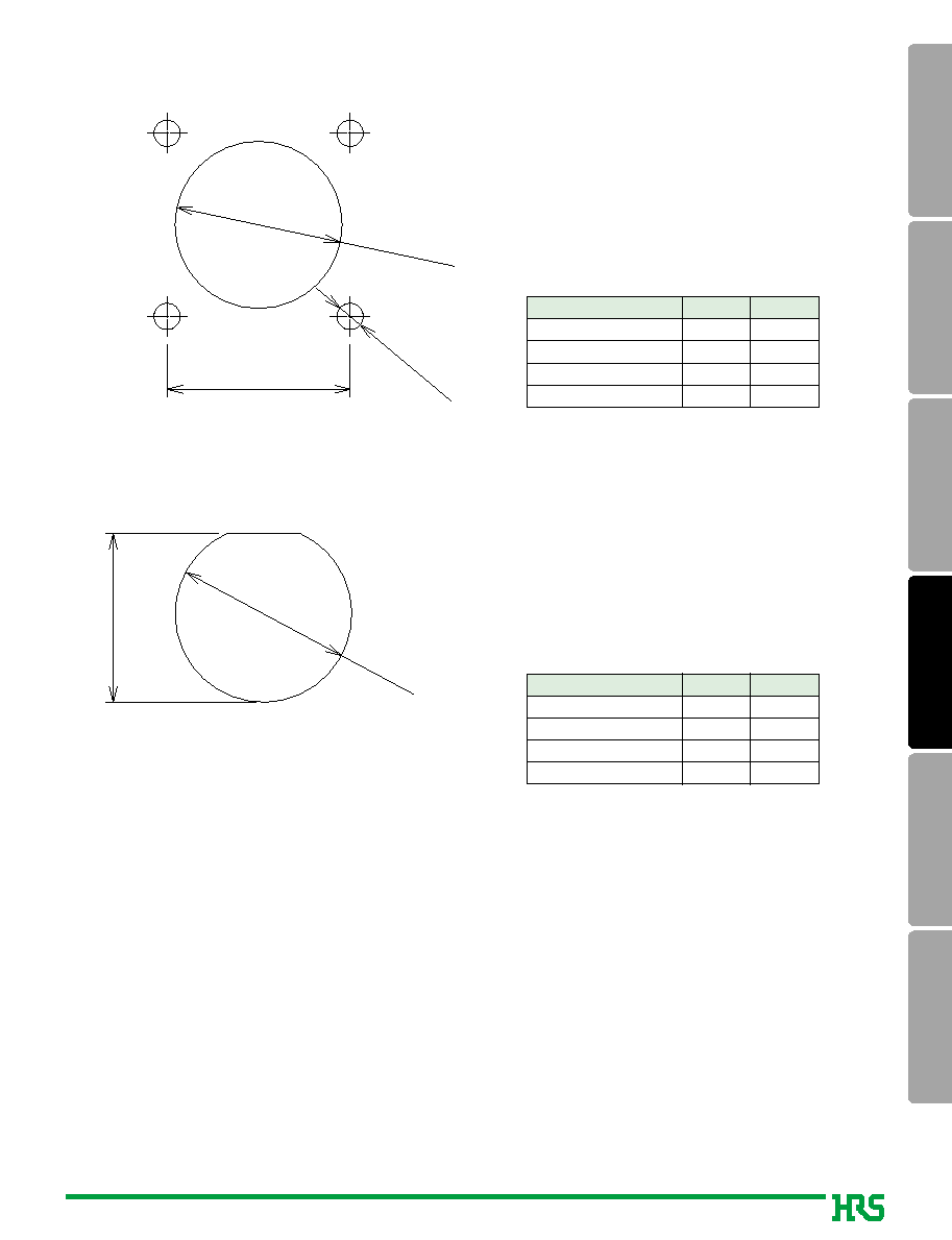
q
Square Flange Receptacle Housing
ØF
G
Ø D
4-
Ø3.3
M E
A
C
B
3
Number of Fibers
M
A
B
C
Ø
D
M
E
Ø
F
G
2
4
30
35
10
10
45.5
51.5
20.5
25.5
23
27
24
27
18.7
18.7
Part Number
MF14B-WRF01-0200
MF17B-WRF01-0400
Note: Up to 3 mm cables are applicable.
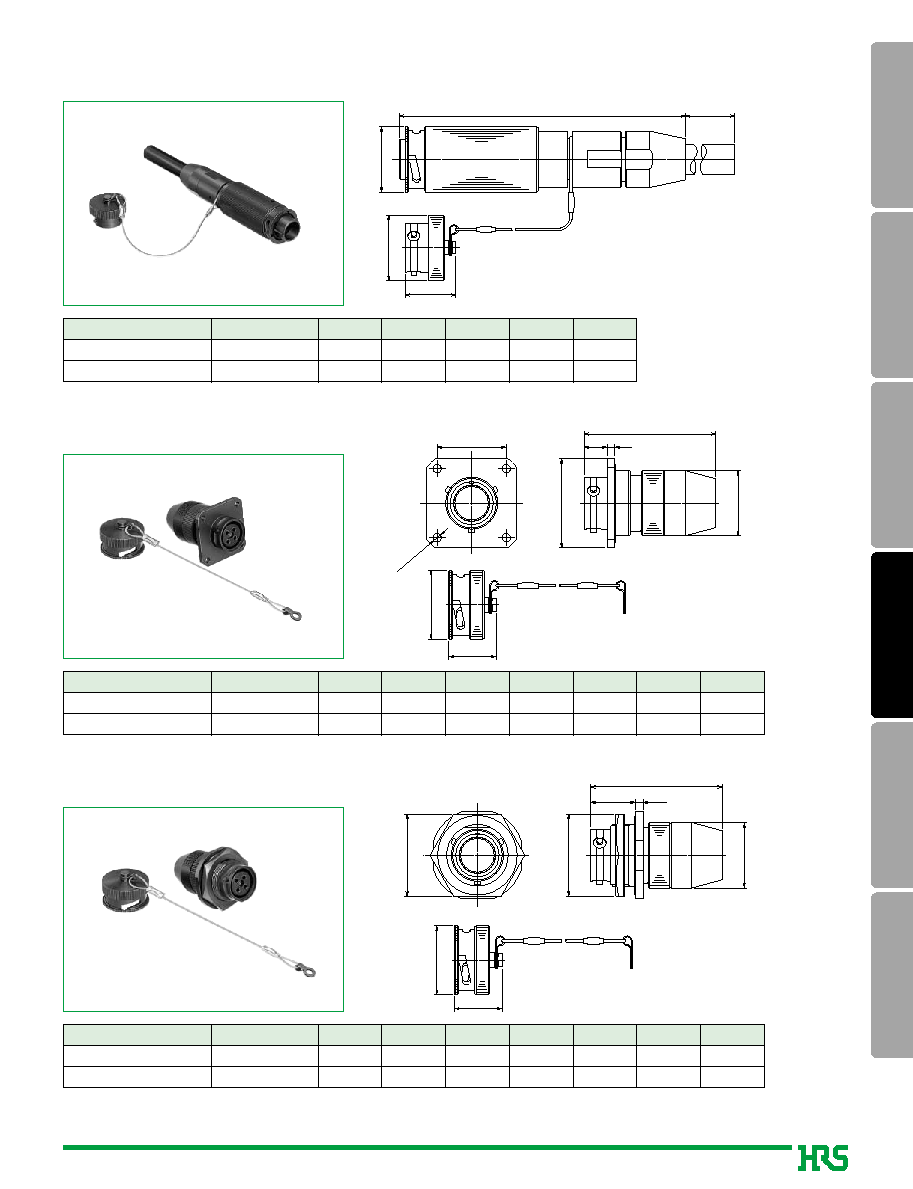
q
Bulk Head Receptacle Housing
ØD
ØF
G
A
C
B
3
E HEX
Number of Fibers
M
A
B
C
Ø
D
M
E
Ø
F
G
2
4
30
34
17.5
17.5
45.5
51.5
20.5
25.5
28
32
24
27
18.7
18.7
Part Number
MF14B-WRB01-0200
MF17B-WRB01-0400
58
MU
SC
FC
Harsh
Environment
Attenuators
Terminators
s
Threaded lock
q
Plug housing
ØD
E
ØA
B
C
F
Note: Up to 3 mm cables are applicable.
q
Square Flange Receptacle Housing
H
ØD
ØG±0.3
4-
Ø3.3
E
MF
M
A
B
3
C
Part Number
M
A
B
C
Ø
D
E
M
F
Ø
G
H
2
4
30
35
10
10
45.5
51.5
20.5
25.5
M20
1
M22
1
23
27
24
27
18.5
18.5
Part Number
MF14S-WRF01-0200
MF17S-WRF01-0400
Note: Up to 3 mm cables are applicable.
q
Bulk Head Receptacle Housing
H
ØD
ØG
E
A
C
B
3
F HEX
Part Number
M
A
B
C
Ø
D
E
M
F
Ø
G
H
2
4
31
34
17.5
17.5
45.5
51.5
20.5
25.5
M20
1
M22
1
30
32
24
27
18.5
18.5
Part Number
MF14S-WRB01-0200
MF17S-WRB01-0400
*
indicates the cable diameter. 8, 9 and 10mm, diameter cables are applicable.
Number of Fibers
Ø
A
B
C
Ø
D
E
F
2
4
24
27
1
84.7
116.5
69
52
24
27
20.8
20.8
M20
1
M22
1
Part Number
MF14S-WP
*
S01-0200
MF17S-WP
*
S01-0400