B2
Simple Assembly Type PC Card Frame Kits
NX1 Series
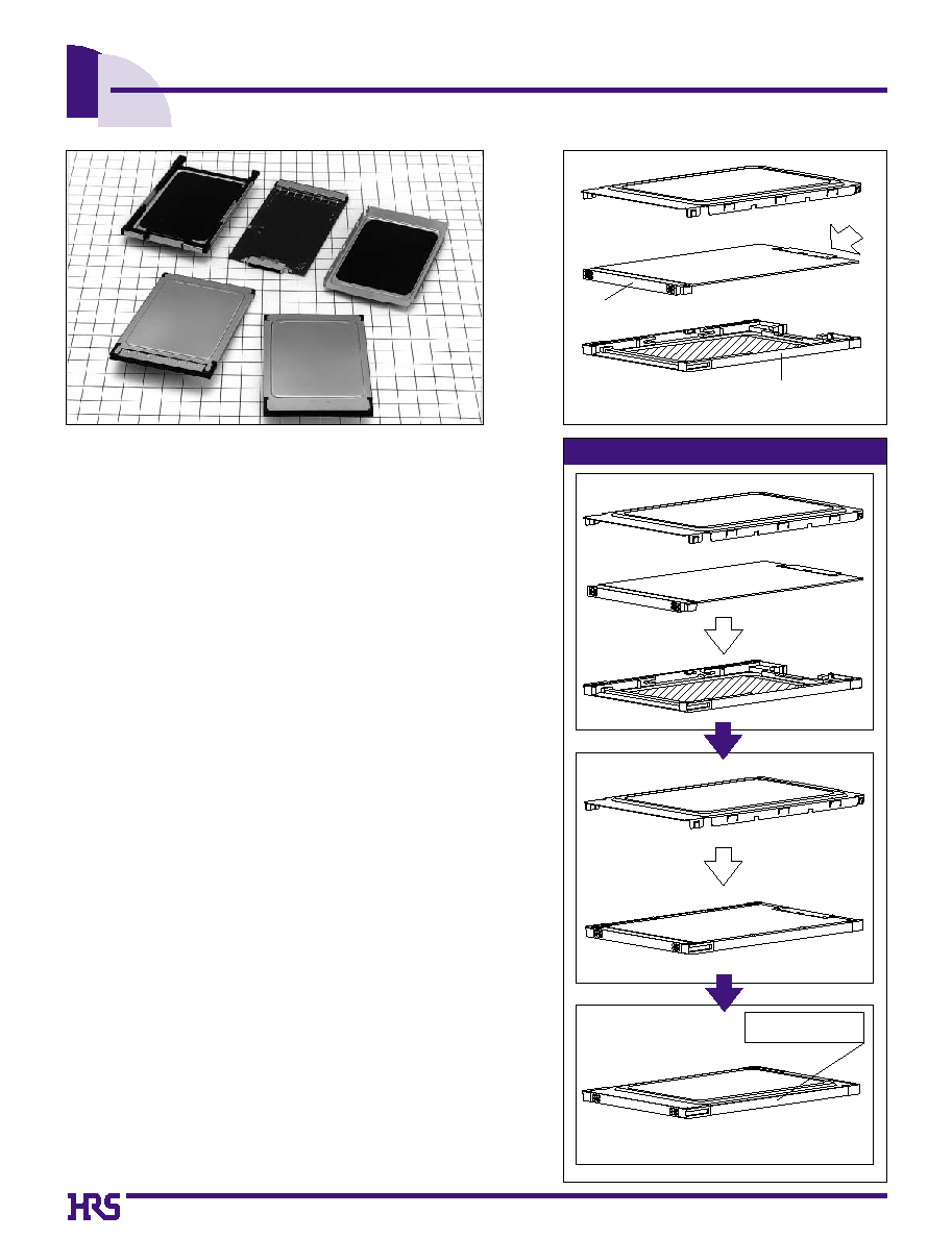
Simple Assembly Method
s
Features
1. Great reduction of the number of frame kit
assembly steps
Use of this simple assembly method has greatly reduced the
number of assembly steps. Processes such heat fusion and
cooling of the covers are no longer required. Assembly of the
frame kit is possible using simple jig tools. (See the Simple
Assembly Method insert to the right.).
2. Excellent Shielding Qualities
The covered construction using a metal panel out to the sides of
the card provide excellent shielding qualities. (See Figure 4.)
3. Board Offset
Available in types with board offsets of 0.3mm and 0.9mm.
4. Back connectors
Back Connectors available with 15,25, and 32 contacts.
5. Can Be Used With CardBus Types
6. Stable Conduction Maintained Between Panels
The spring quality of the metal ensures stable conduction to be
maintained between the panels at the panel lock portion.
7. Conduction Maintained Between Panel and Board
The cunduction between panel and board is maintained by
contact between the panel and a one-body ground spring.
s
Applications
A wide variety of PC cards including LAN, FAX modem, and
SCSI.
Figure 1
Figure 4
Figure 3
Figure 2
Frame+Metal panel
68-contact socket
Back connector
Metal panel covers all the
way to the card sides
(For details, see the frame Kit assembly procedure on page 6)
B3
NX1B L - 32 T - KT 3 B (05)
q
w
e r
t y u i
s
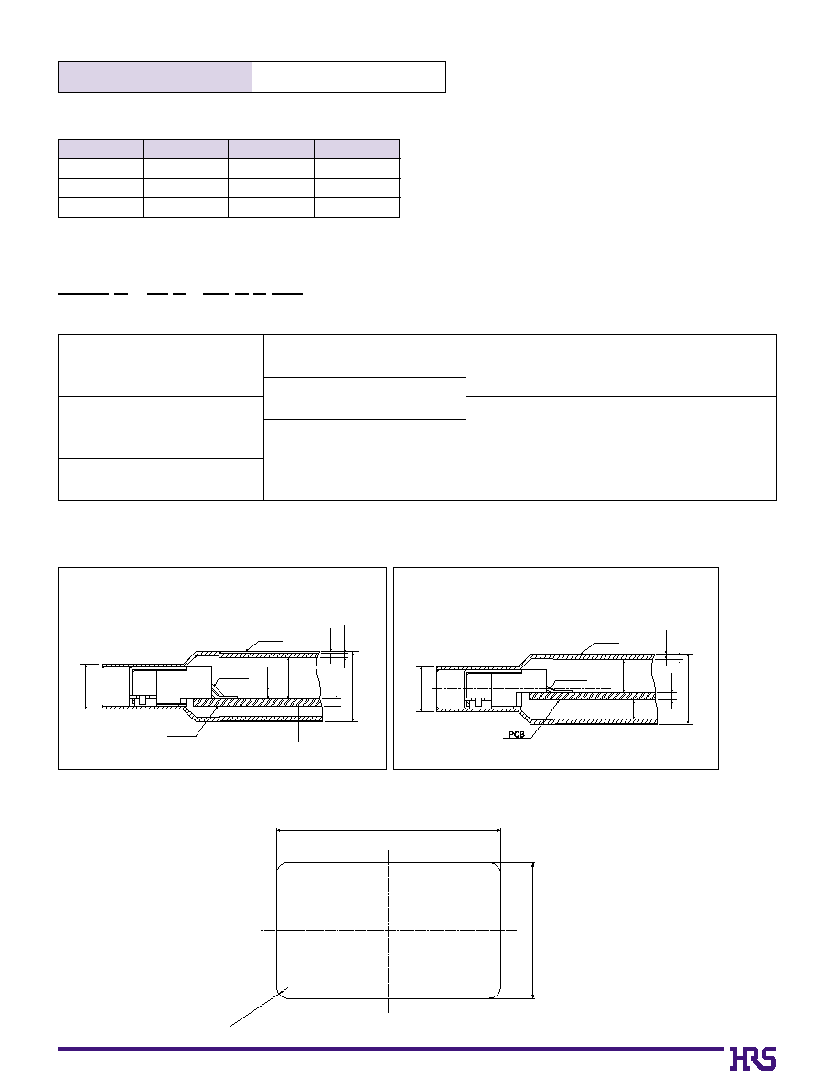
Ordering Information
s
Materials
s
Product Rating
q
Series name
NX1 : General type
NX1B : Card bus type
r
Suitable back connectors
T: NX Series
u
Type of suitable 68-contact connectors
K: General type (IC1K Series)
B: Card Bus type (IC9 Series)
i
Presence of insulation tape
05 : With insulation tape
06 : Without insulation tape
t
Connector type
KT: Frame kit
y
Offset
3: 0.3mm
9: 0.9mm
w
Card key type
None : 5 V type
L
: 3.3 V type
e
Number of back connector
15, 25, or 32
s
Connector Mounting Condition
q
0.9mm Offset Type
q
0.3mm Offset Type
(Panel thickness
+ Insulation tape thickness)
0.25
5 MAX
0.5 MAX
3.1
0.8
0.9
3.3
Panel
SMT
contacts
Connector
portion
PCB
0.05
3.3
(Panel thickness
+ Insulation tape thickness)
0.25
5 MAX
0.5 MAX
2.5
1.4
0.3
Panel
SMT
contacts
Connector
portion
0.05
s
Label Dimensions(Recommended Label Thickness: 50�m)
38�0.2
63�0.2
4-R3.5�0.2
Operating temperature range
Part
Material
Color
Remarks
UL94V-0
-------
510-FR
Black
Dull Finish
Black
PBT
Stainless steel
Polyester
Frame
Panel
Insulation tape
-
30
�
to
+
70
�
B4
Suitable 68-Contact Socket Connectors
Suitable Back Connectors
Part Number
NX60TB-15SAA9-SP
NX60TB-15SAA3-SP
NX60TA-25SAA9-SP
NX60TA-25SAA3-SP
NX60T
B
-32SAA9-SP
NX60TA-32SAA3-SP
Part Number
IC1K-68RD-1.27SFA
IC1K-68RD-1.27SF
IC1K-68RD-1.27SFA
IC1K-68RD-1.27SF
IC1K-68RD-1.27SFA
IC1K-68RD-1.27SF
CL No.
640-0047-2
640-0046-0
640-0047-2
640-0046-0
640-0047-2
640-0046-0
s
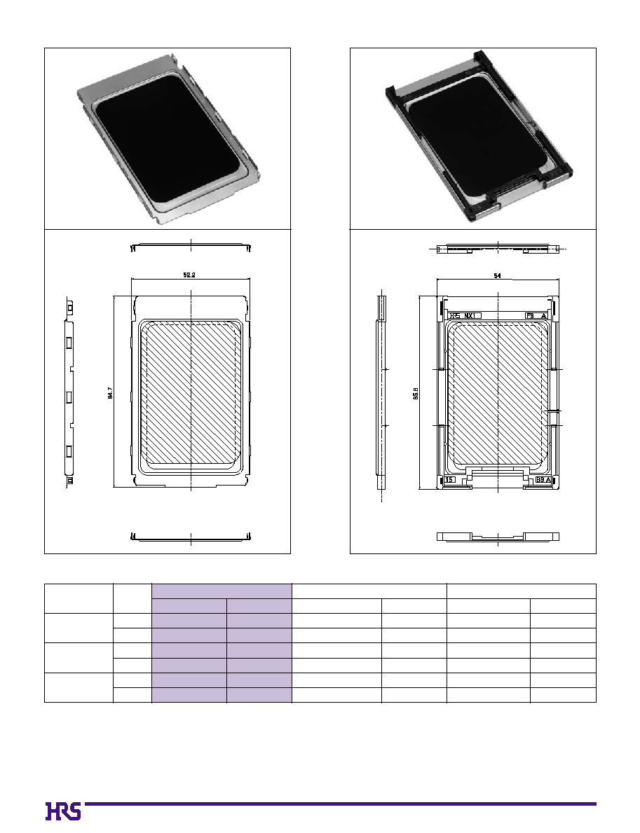
NX1 Series (General Type Frame Kit)
Panel A
Panel B
Number of
Contacts
15
25
32
Offset
(mm)
0.9
0.3
0.9
0.3
0.9
0.3
Frame Kit
Part Number
NX1-15T-KT9K(
**
)
NX1-15T-KT3K(
**
)
NX1-25T-KT9K(
**
)
NX1-25T-KT3K(
**
)
NX1-32T-KT9K(
**
)
NX1-32T-KT3K(
**
)
CL No.
234-2102-5-
**
234-2103-8-
**
234-2104-0-
**
234-2105-3-
**
234-2106-6-
**
234-2107-9-
**
CL No.
234-0097-6
234-0098-9
234-0107-8
234-0033-3
234-0023-0
234-0053-0
(
**
) : (05) : With Insulation type
(
**
) :
(06) : Without Insulation type

B5
s
NX1B Series (Card Bus Type Frame Kit)
Panel A
Panel
B
Suitable 68-Contact Socket Connectors
Suitable Back Connectors
Part Number
NX60TB-15SAA9-SP
NX60TB-15SAA3-SP
NX60TA-25SAA9-SP
NX60TA-25SAA3-SP
NX60T
B
-32SAA9-SP
NX60TA-32SAA3-SP
Part Number
IC9-68RD-0.635SFA
IC9-68RD-0.635SF
IC9-68RD-0.635SFA
IC9-68RD-0.635SF
IC9-68RD-0.635SFA
IC9-68RD-0.635SF
CL No.
640-0902-5
640-0901-2
640-0902-5
640-0901-2
640-0902-5
640-0901-2
Number of
Contacts
15
25
32
Offset
(mm)
0.9
0.3
0.9
0.3
0.9
0.3
Frame Kit
Part Number
NX1BL-15T-KT9B
(
**
)
NX1BL-15T-KT3B
(
**
)
NX1BL-25T-KT9B
(
**
)
NX1BL-25T-KT3B
(
**
)
NX1BL-32T-KT9B
(
**
)
NX1BL-32T-KT3B
(
**
)
CL No.
234-2153-6
-
**
234-2154-9
-
**
234-2157-7
-
**
_______
234-2155-1
-
**
234-2156-4
-
**
CL No.
234-0097-6
234-0098-9
234-0107-8
234-0033-3
234-0023-0
234-0053-0
(
**
) : (05) : With Insulation type
(
**
) :
(06) : Without Insulation type
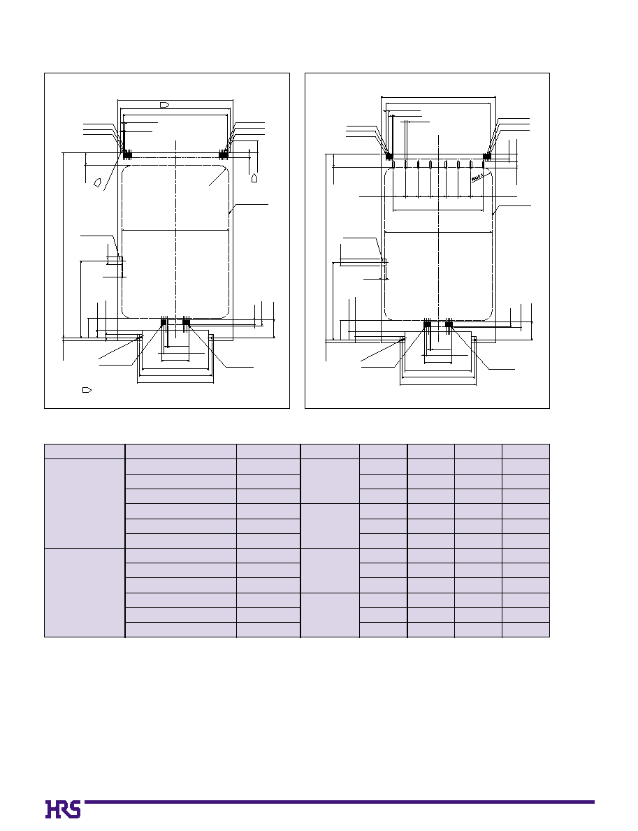
B6
NOTE
Connector mounting side
The dimensions portion of the diagram(i.e.,the dotted
line portion) is not required when a positioning jig or
another aid is used to mount the connectors.
Contact No.2
Contact No.67
Contact No.34
Contact No.68
P=0.635�0.03
68-0.4�0.02
0.63567=42.545�0.05
Contact No.35
Contact No.1
47
0
-0.1
45
+
0.1
+
0
1
4.6�0.1
2�0.1
5.4�0.1
76�0.1
31.65�0.1
Last contact No.
1.5�0.1
7.4�0.1
Contact No.1
P=0.8�0.05
B�0.1
A�0.1
D�0.1
1.1�0.1
8�0.1
Ground clip pad
3�0.1
2�0.1
44�0.2
R4�0.1
R0.5 MAX
1
1
Valied parts
mounting area
3.3
+
0.1
+
0
f 0.6
+
0.1
+
0
2
0 -0.05
2.4
0 -0.05
0.5
0
-0.05
C
+
0.1
+
0
1
Connector mounting side
Contact No.2
Contact No.67
Contact No.34
Contact No.68
P=0.635�0.03
68-0.4�0.02
8-0.8�0.1
0.63567=42.545�0.05
Contact No.35
Contact No.1
47
0
-0.2
2�0.1
3�0.1
2.5�0.1
76�0.1
3�0.1
Last contact No.
Contact No.1
P=0.8�0.05
B�0.1
A�0.1
D�0.1
Ground clip pad
Valied parts
mounting area
5.08�0.1
44�0.2
5.08�0.1
36.83�0.15
6.35�0.1
5.08�0.1
5.08�0.1
5.08�0.1
f 0.6
+
0.1
+
0
0.5
0
-0.05
C
+
0.1
+
0
5.08�0.1
5.4�0.1
7.4�0.1
2
0 -0.05
2.4
0 -0.05
3.3
+
0.1
+
0
1.1�0.1
8�0.1
31.65�0.1
1.5�0.1
2�0.1
B
Board Dimensions (Applicable Board Thickness: 0.5 mm Max.)
q
NX1 Series (General Type)
q
NX1B Series (CardBus Type)
A
B
C
D
31.2
39.2
44.8
31.2
39.2
44.8
31.2
39.2
44.8
31.2
39.2
44.8
29.8
37.8
43.4
29.8
37.8
43.4
29.8
37.8
43.4
29.8
37.8
43.4
27.2
35.2
40.8
27.2
35.2
40.8
27.2
35.2
40.8
27.2
35.2
40.8
11.2
19.2
24.8
11.2
19.2
24.8
11.2
19.2
24.8
11.2
19.2
24.8
Offset
0.9
0.3
0.9
0.3
Number of Contacts
15
25
32
15
25
32
15
25
32
15
25
32
Part Number
NX1-15T-KT9K(
**
)
NX1-25T-KT9K(
**
)
NX1-32T-KT9K(
**
)
NX1-15T-KT3K(
**
)
NX1-25T-KT3K(
**
)
NX1-32T-KT3K(
**
)
NX1BL-15T-KT9B(
**
)
NX1BL-25T-KT9B(
**
)
NX1BL-32T-KT9B(
**
)
NX1BL-15T-KT3B(
**
)
NX1BL-25T-KT3B(
**
)
NX1BL-32T-KT3B(
**
)
Type
NX 1Series
(General Type)
NX1B Series
(Card Bus Type
Frame Kit)
Please use "NX Series Flame Kit (Not N X 1) "when print processing the panel.
(
**
) : (05) : With Insulation type
(
**
) :
(06) : Without Insulation type
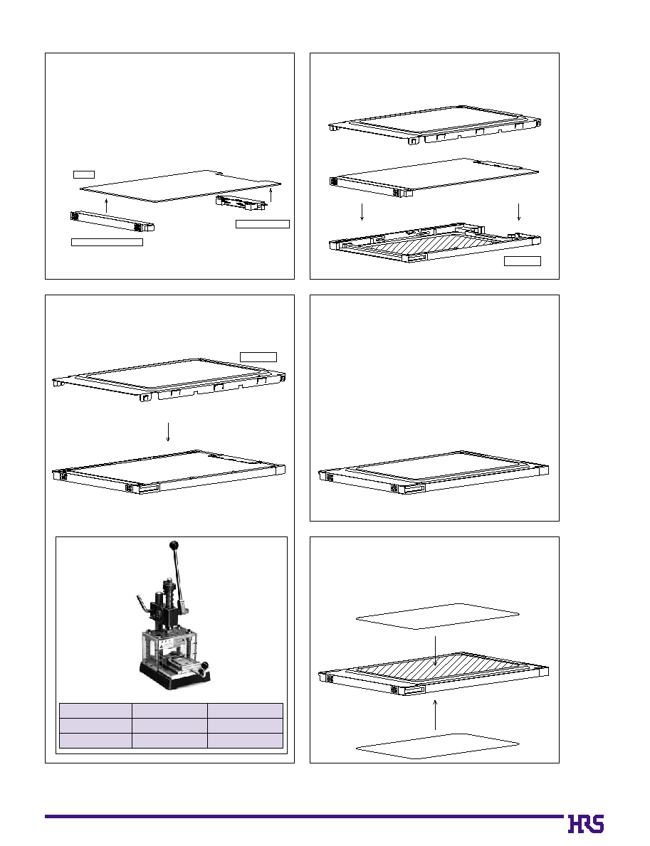
B7
B
Frame Kit Assembly Process
Assembly Process Figure 1
Mount the connectors(68-contact connectors,
back connectors) and other parts to the
printed circuit board (PCB).
NOTE :The procedure for the IC9 Series (suited to the
68-contact connectors and card bus) is to mount
the connector body, then insert the ground plate
and fasten the lead portion by hand.
Assembly Process Figure 2
Insert the PCB mounting part to panel B
(frame press fitting item).
Assembly Process Figure 3
Use the assembly jig (described below) to
insert panel A. (Press fit + lock)
Assembly Process Figure 4
Assembled item
Assembly Process Figure 5
Affix the label to the indented portion of the panel.
NOTE :Hirose Electric Co. Ltd. will not provide label services.
(Please refer to the Recommended Label Dimensions
Diagram of Page 2.)
Assembly Jig
(The photograph shows the hand press model.)
Panel B
Panel A
Part Number
NX1-/CVCK-MP
NX1-/CVCK-MP(01)
CL No.
902-3530-7
902-3530-7(01)
Classification
Without hand press
With hand press
PCB
68-Contact connector
Back connector