
A27
Product Compliant to DIN41612/IEC603-2 Standard
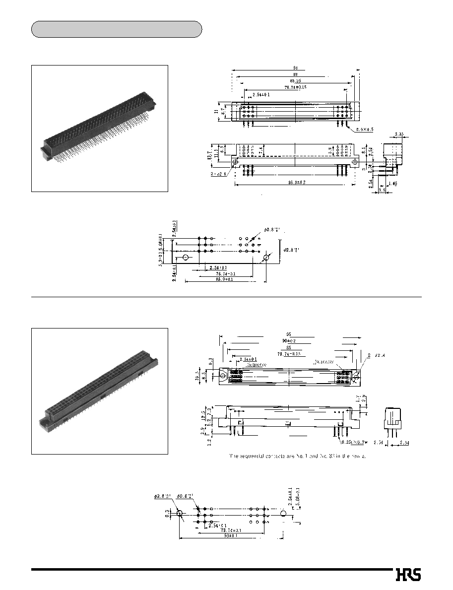
PCN Series
Pin Header Side
q
Straight through hole type
Receptacle Side
q
Straight through hole
PCN10
EA
-
* *
S-2.54DSA
PCN10C
A
-
* *
S-2.54DSA
PCN10EA-
* *
S-2.54DSA
PCN10D
A
-
* *
S-2.54DSA
PCN12
EA
-
* *
S-2.54DSA
PCN12E
A
-
* *
S-2.54DSA
PCN13
EA
-
* *
S-2.54DSA
q
Stacking through hole type
q
Right angle through hole type (mounted on the board edge)
q
Right angle through hole type (mounted on the board)
q
Press fit type
q
Wrapping type
PCN10
EA
-
* *
S-2.54W
*
q
Right angle through hole type (mounted on the board edge)
PCN10B
A
-
* *
S-2.54DS
q
Right angle through hole type (mounted on the board)
PCN10A
E
-
* *
S-2.54DS
PCN10C
A
-
* *
S-2.54DS
PCN13
EA
-
* *
S-2.54DS
q
Press fit short pin type
PCN11-
* *
S-2.54PFB-2
q
Press fit long pin type
PCN11-
* *
S-2.54WB-2
q
Cable type
PCN10-
* *
S-2.54C
+
PCN10-
* * * *
SC
*
PCN10-
* *
S-2.54R
PCN10
EA
-
* *
P-2.54DSA
PCN10H
*
-
* *
P-2.54DSA
PCN10
EA
-
* *
P-2.54DS
PCN12
EA
-
* *
P-2.54DS
PCN12E
A
-
* *
P-2.54DS
PCN10A
E
-
* *
P-2.54DS
PCN10EA-
* *
P-2.54DS
PCN12A
E
-
* *
P-2.54DS
PCN12EA-
* *
P-2.54DS
PCN11-
* *
P-2.54W
*
-2
+
PCN11-
* *
P-2.54H-2

A70
B
Application Pattern
s
Circuit Protection Function Type
q
2-row type
q
3-row type
'
: Mounting hole center
C.L. :Center line
s
Stacking Connector
*
G : 35, 30, 25, 45, 40
'
: Mounting hole center
C.L. :Center line
64 contacts :
The sequential contacts
are indicated at 22
points to contact No.1 to
4 and 26 to 32 in both
rows a and b.
100 contacts :
The sequential contact
is indicated at 22 points
to contact No.1 to 4 and
44 to 50 in both rows a
and b.
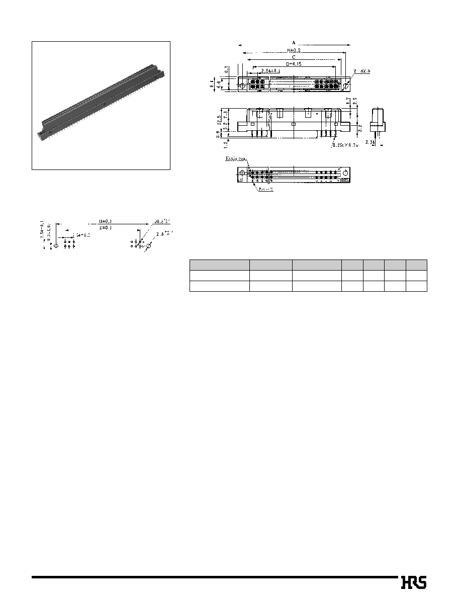
The sequential contacts are
located at 22 points to a1
and a32.

A28
Pin Header Side
q
Right angle through hole type (mounted on the board edge)
Receptacle Side
q
Straight through hole type
PCN10F
A
-
* *
S-2.54DSA
s
Coaxial Connector and High Current Contact Composite Type
q
Right angle through hole type (mounted on the board)
q
Wrapping type
PCN10F
A
-
* *
S-2.54W
*
q
Right angle through hole type (mounted on the board edge)
PCN10FB-
* *
S-2.54DS
q
Right angle through hole type (mounted on the board)
PCN10FA-
* *
S-2.54DS
q
Press fit short pin type
PCN11F-
* *
S-2.54PFB-2
q
Press fit long pin type
PCN11F-
* *
S-2.54WB-2
Circuit Protection Function Type
Pin Header Side
q
Right angle through hole type
Receptacle Side
PCN10MC
*
-
* *
P-2.54DS
q
Straight through hole type
PCN10MC
*
-
* *
S-2.54DSA
q
Wrapping type
PCN10MC
*
-
* *
S-2.54W
*
PCN10F-
* *
P-2.54DS
PCN10FA-
* *
P-2.54DS

A29
s
Features
1. Compliant with DIN Standard
Comply with IEC603-2/DIN41612 standard.
2. Variation in number of contacts
10, 16, 20, 24, 28, 30, 32, 44, 48, 50, 64, 90, 96, 100, 128, and
144 contacts are available.
3. Two point contact construction
PCN10 and 12 series are constructed with high reliable double-
sided two point contacts.
PCN13 series pursues after cost performance, and constructed
with single sided two point contacts.
4. Broad applications
DIN standard types of B, C, R, and Q are available. The flux tight
product is available. The easy lock pin type to prefix the board is
available.
5. Stacking height variation
PCN10H series contains 25, 30, 35, 40 and 45mm stacking
height.
6. Circuit protection function available
PCN10MC series utilizes a sequence structure for circuit
protection function.
7. Cable connector
ID connector for ribbon cable is available.
The connector is prepared for crimping connection for AWC#26
to
30 cables.
s
Application
Control equipment, exchange, measuring instruments etc.
Single-sided two point Contact System
Stacking Connector
Double-sided two point Contact System
PCN10, 12, 13 Series (Product Compliant to DIN Standard: through hole,Wrapping Type)
PCN Series

A30
s
Product Specifications
s
Ordering Information
PCN10 A �
*
P � 2.54 DS
s
Material
1
2
4
3
5
6
100V DC
1000V AC (insulation displacement, crimping type: 650V AC) /1 minute.
0.1A
Frequency: 10 to 55 Hz, single amplitude of 0.75 mm, 2 hours in each of the 3 directions.
96 hours at temperature of 40� and humidity of 90% to 95%
500 cycles
Manual soldering: 300� for 3 seconds
10
6
M
ohms
No flashover or insulation breakdown.
20m ohms max.
No electrical discontinuity of 10�s or more
Insulation resistance : 10
6
M
ohms
min.
Contact resistance : 20m
ohms
max.
No deformation of components affecting performance.
No damage, cracks, or parts looseness.
(-65
�
: 30 minutes
�
15 to 35
�
: 5 minutes max.
�
125
�
: 30 minutes
�
15 to 35
�
: 5 minutes max.) 5 cycles
1.Insulation Resistance
2.Withstanding Voltage
3.Contact Resistance
4.Vibration
5.
Humidity(Steady state)
6.Temperature Cycle
7.Durability (Mating/un-mating)
8.Resistance to Soldering heat
Item
Specification
Condition
Note 1: Includes temperature rise caused by current flow.
Note 2: The term "storage" refers to products stored for long period of time prior to mounting and use. Operating Temperature Range and
Humidity range covers non conducting condition of installed connectors in storage, shipment or during transportation.
Parts
Material
Finish
Remarks
Contact
Insulator
Pin header
Receptacle
PBT
Brass
Copper alloy
Gray
Contact area: Gold plated
Remainer: Tin-lead plated
UL94V-0
---------------
---------------
Rating
Current rating: 2A
Voltage rating: 300V AC
Operating Temperature Range:
-
55
to
+85
� (Note 1)
Operating Humidity Range: 85
% max
Storage Temperature Range:
-
10
to
+60
� (Note 2)
Storage Humidity Range: 40
to
70
% (Note 2)
q
PCN 10 Series
Series Name
: PCN10
Blank
A
mold type (as listed below)
B
C : Flux prevention type (DSA only)
D : Rack installation type
EA : With Board prefixed lock pin
H : Stacking height 35mm type
HA : Stacking height 30mm type
HB : Stacking height 25mm type
HC : Stacking height 45mm type
HD : Stacking height 40mm type
MC : Circuit Protection function type
Connector type
: P
: Pin header
: S
: Receptacle
Contact pitch
: 2.54mm
Contact type
DS
: Right angle through hole type
DSA : Straight through hole type
WA : Wrapping type (0.5tx0.7W)
WB : Wrapping type (0.5tx0.5W)
R
: Insulation displacement type
C
: Crimping type
Number of contacts: 2-row : 16, 20, 24, 32, 44, 50, 64, 90, 100
3-row : 48, 96, 144
4-row : 128
1
2
3
4
5
6
}
*
*

A31
PCN12 A -
*
P - 2.54 DS
1
2
4
3
5
6
PCN12 E -
*
S - 2.54 DSA
1
2
4
3
5
6
PCN13 E -
*
S - 2.54 DSA
1
2
4
3
5
6
*
PCN13 series are only socket type.
PCN10 and 12 series are mating connectors.
q
PCN 12 Series (Plug)
q
PCN 12E-
*
S-2.54 DSA(Socket)
r
S
: Socket
t
Contact pitch
: 2.54mm
y
Contact type
: DSA: Straight through hole type
q
Series name
: PCN12
w
No symbol
: Standard type
E
: With board prefixed lock pin type
e
Number of contacts : 2-row: 10, 16, 20, 28, 32, 44, 50,
64, 90, 100
3-row: 96
q
PCN 13E-
*
S-2.54 DSA (Socket)
e
Number of contacts : 2-row: 10, 16, 20, 24, 28, 32, 44,
50, 64, 90, 100
3-row: 96
r
P
: Plug
t
Contact pitch
: 2.54mm
y
Contact type
: DS: Right angle through hole type
q
Series name
: PCN12
w
No symbol
: DIN standard type C (96 Contacts)
A
: Original type
E-EA
: With board prefixed lock pin type
r
S
: Socket
t
Contact pitch
: 2.54mm
y
Contact style
: DS: Right angle through hole type
: DSA: Straight through hole type
q
Series name : PCN13
w
No symbol
: Standard type
E
: With board prefixed easy pin type
e
Number of contacts : 2-row: 10, 16, 20, 30, 32, 44, 50,
64, 90, 100
3-row: 48, 96

A32
B
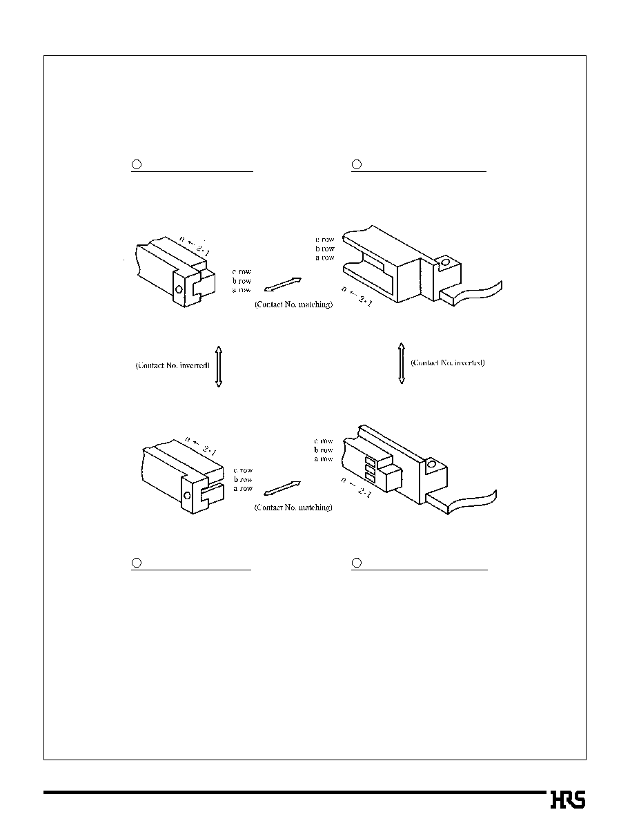
DIN Connector Mating Condition
DIN connectors of Hirose should be used under conditions as illustrated below.
A33
B
Contact numbers
Receptacle straight type
Type C (Type B)
According to the inter-combination with DIN standard type C (type B) and type R (type Q), the contact numbers
and row numbers represent contact No. (No.1 to 32) and row No. (a, b, c).
q
DIN standard type C and type R represent the 3-row 96 contacts type, including 32 contacts in single-row.
q
DIN standard type B and type Q represent the 2-row 64 contacts type, including 32 contacts in single-row.
Note: The DIN connector is basically standardized in combination with straight and right angle types. As shown
above in illustrationss;
The contact numbers is matched in combination with (1)-(2) and (3)-(4), while the contact numbers are
inverted in combination with (1)-(2) and (3)-(4).
Pin header right angle type
Type C (Type B)
Pin header straight type
Type R (Type Q)
Receptacle right angle type
Type R (Type Q)
1
2
3
4

A34
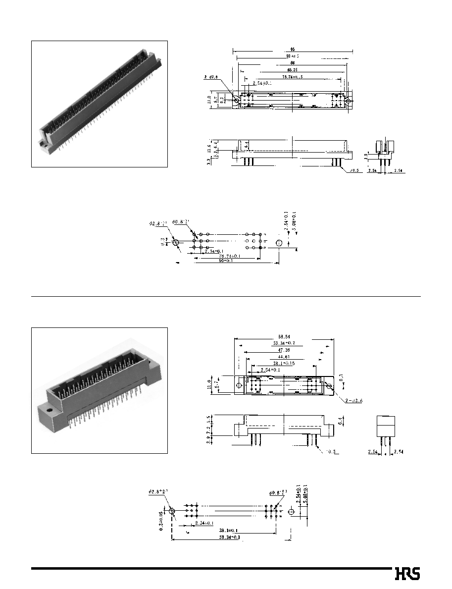
PCN10 Series
s
Pin Header: 2-row Right Angle Type (DIN standard type B)
PCN10-
*
P-2.54DS
PCN10A-
*
P-2.54DS
CL No.
Part Number
Unit:mm
583-0231-1
583-0078-6
583-0011-5
583-0039-4
583-0012-8
583-0013-0
583-0014-3
583-0114-8
PCN10A-
0
16P-2.54DS
PCN10A-
0
20P-2.54DS
PCN10A-
0
32P-2.54DS
PCN10A-
0
44P-2.54DS
PCN10A-
0
50P-2.54DS
PCN10A-
0
64P-2.54DS
PCN10A-
0
90P-2.54DS
PCN10A-100P-2.54DS
Number of Contacts
16
20
32
44
50
64
90
100
A
B
33.04
38.12
53.36
68.6
0
76.22
94
.00
127.02
139.72
24.39
29.47
44.71
59.95
67.57
85.35
118.37
131.07
C
D
17.78
22.86
38.1
0
53.34
60.96
78.74
111.76
124.46
27.94
33.02
48.26
63.5
0
71.12
88.9
0
121.92
134.62
Unit:mm
CL No.
Part Number
583-0230-9
583-0077-3
583-0015-6
583-0038-1
583-0016-9
583-0017-1
583-0018-4
583-0113-5
PCN10- 16P-2.54DS
PCN10- 20P-2.54DS
PCN10- 32P-2.54DS
PCN10- 44P-2.54DS
PCN10- 50P-2.54DS
PCN10- 64P-2.54DS
PCN10- 90P-2.54DS
PCN10-100P-2.54DS
Number of Contacts
16
20
32
44
50
64
90
100
A
B
33.04
38.12
53.36
68.6
0
76.22
94
.00
127.02
139.72
24.39
29.47
44.71
59.95
67.57
85.35
118.37
131.07
C
D
27.94
33.02
48.26
63.5
0
71.12
88.9
0
121.92
134.62
B
PCB mounting pattern
B
PCB mounting pattern
s
Pin Header: 2-row Right Angle Type
17.78
22.86
38.1
0
53.34
60.96
78.74
111.76
124.46

A35
PCN10EA
*
P-2.54DS
PCN10-
*
P-2.54DSA
Unit:mm
CL No.
Part Number
583-0256-2
583-0181-5
583-0182-8
583-0183-0
583-0184-3
583-0185-6
583-0186-9
583-0187-1
PCN10EA-
0
16P-2.54DS
PCN10EA-
0
20P-2.54DS
PCN10EA-
0
32P-2.54DS
PCN10EA-
0
44P-2.54DS
PCN10EA-
0
50P-2.54DS
PCN10EA-
0
64P-2.54DS
PCN10EA-
0
90P-2.54DS
PCN10EA-100P-2.54DS
Number of Contacts
16
20
32
44
50
64
90
100
A
B
33.04
38.12
53.36
68.6
0
76.22
94
.00
127.02
139.72
24.39
29.47
44.71
59.95
67.57
85.35
118.37
131.07
C
D
27.94
33.02
48.26
63.5
0
71.12
88.9
0
121.92
134.62
B
PCB mounting pattern
17.78
22.86
38.1
0
53.34
60.96
78.74
111.76
124.46
q
The PCB mounting pattern is
equivalent to PCN10A-
*
P-2.54DS.
(Refer to page A34.)
Note: DIN standard type Q (Reverse type of type B) indicates PCN10Q-64P-2.54DSA.
*
Type Q differs in the outer dimensions and PCB mounting pattern.
s
Pin Header: 2-row Straight Type
s
Pin Header: 2-row Right Angle Type
q
With Board prefixed lock pin
CL No.
Part Number
Unit:mm
583-0139-9
583-0007-8
583-0488-8
583-0008-0
583-0009-3
583-0010-2
583-0251-9
PCN10-
0
20P-2.54DSA
PCN10-
0
32P-2.54DSA
PCN10-
0
44P-2.54DSA
PCN10-
0
50P-2.54DSA
PCN10-
0
64P-2.54DSA
PCN10-
0
90P-2.54DSA
PCN10-100P-2.54DSA
Number of Contacts
20
32
44
50
64
90
100
A
B
43.3
0
58.54
73.78
81.4
0
99.18
132.2
0
144.9
0
38.1
0
53.34
68.58
76.2
0
93.98
127
.00
139.7
0
C
D
29.47
44.71
59.95
67.57
85.35
118.37
131.07
22.86
38.1
0
53.54
60.96
78.74
111.76
124.46
Note

A36
PCN10-
*
S-2.54DSA
B
PCB mounting pattern
s
Receptacle: 2-row Straight Type (DIN standard type B)
PCN10C-
*
S-2.54DS
B
PCB mounting pattern
s
Receptacle: 2-row Right Angle Type
Note
Note: DIN standard type Q (Reverse type of type B) indicates PCN10B-64S-2.54DS.
*
Type Q differs in the external size and PCB mounting pattern.
CL No.
Part Number
Unit:mm
583-0019-7
583-0020-6
583-0021-9
583-0022-1
PCN10-32S-2.54DSA
PCN10-50S-2.54DSA
PCN10-64S-2.54DSA
PCN10-90S-2.54DSA
Number of Contacts
32
50
64
90
A
B
54.36
77.22
95
.00
128.02
49.36
72.22
90
.00
123.02
C
D
44.36
67.22
85
.00
118.02
38.1
0
60.96
78.74
111.76
Unit:mm
CL No.
Part Number
583-0201-0
583-0202-3
583-0052-2
583-0168-7
583-0174-0
583-0203-6
583-0204-9
583-0178-0
PCN10C-20S-2.54DS
PCN10C-32S-2.54DS
PCN10C-44S-2.54DS
PCN10C-50S-2.54DS
PCN10C-60S-2.54DS
PCN10C-64S-2.54DS
PCN10C-90S-2.54DS
PCN10C-100S-2.54DS
Number of Contacts
20
32
44
50
60
64
90
100
A
B
43.1
0
58.34
73.58
81.2
0
93.9
0
98.98
132
.00
144.7
0
29.12
44.36
59.6
0
67.22
79.92
85
.00
118.02
130.72
C
D
38.1
0
53.34
68.58
76.2
0
88.9
0
93.98
127
.00
139.7
0
22.86
38.1
0
53.34
60.96
73.66
78.74
111.76
124.46

A37
B
PCB mounting pattern
s
Flux Prevention Type (DIN standard type B)
PCN10-
*
S-2.54
WA
WB
B
PCB mounting pattern
s
Receptacle: 2-row Wrapping Type (DIN standard type B)
Unit:mm
CL No.
Part Number
583-0226-1
583-0079-9
583-0033-8
583-0034-0
583-0035-3
583-0036-6
583-0037-9
583-0112-2
PCN10C-
0
16S-2.54DSA
PCN10C-
0
20S-2.54DSA
PCN10C-
0
32S-2.54DSA
PCN10C-
0
44S-2.54DSA
PCN10C-
0
50S-2.54DSA
PCN10C-
0
64S-2.54DSA
PCN10C-
0
90S-2.54DSA
PCN10C-100S-2.54DSA
Number of Contacts
16
20
32
44
50
64
90
100
A
B
34.04
39.12
54.36
69.6
0
77.22
95
.00
128.02
140.72
29.04
34.12
49.36
64.6
0
72.22
90
.00
123.02
135.72
C
D
24.04
29.12
44.36
59.6
0
67.22
85
.00
118.02
130.72
0
17.78
0
22.86
0
38.1
0
0
53.34
0
60.96
0
78.74
111.76
124.46
PCN10C-
*
S-2.54DSA
Unit:mm
CL No.
Part Number
583-0107-2
583-0067-0
583-0068-2
583-0109-8
583-0069-5
583-0110-7
583-0070-4
PCN10-32S-2.54WA
PCN10-32S-2.54WB
PCN10-50S-2.54WB
PCN10-64S-2.54WA
PCN10-64S-2.54WB
PCN10-90S-2.54WA
PCN10-90S-2.54WB
Number of Contacts
32
32
50
64
64
90
90
A
B
54.36
54.36
77.22
95
.00
95
.00
128.02
128.02
49.36
49.36
72.22
90
.00
90
.00
123.02
123.02
C
D
0
38.1
0
0
38.1
0
0
60.96
0
78.74
0
78.74
111.76
111.76
44.36
44.36
67.22
85
.00
85
.00
118.02
118.02
*

A38
A38
PCN10EA
*
S-2.54DSA
q
The PCB mounting pattern is equivalent to
PCN10-
*
P-2.54DSA and PCN10C-
*
P-2.54DSA.
(Refer to catalog page A36 and A37.)
s
Board Prefixed Lock Pin Type (DIN standard type B)
q
Flux prevention type
PCN10D
*
S-2.54DSA
s
Receptacle: 2-row Straight Type (Rack installation type)
B
PCB mounting pattern
Unit:mm
CL No.
Part Number
583-0055-0
583-0056-3
583-0057-6
PCN10D-50S-2.54DSA
PCN10D-64S-2.54DSA
PCN10D-90S-2.54DSA
Number of Contacts
50
64
90
A
B
77.22
95
.00
128.02
72.22
90
.00
123.02
C
D
60.96
78.74
111.76
67.22
85
.00
118.02
Unit:mm
CL No.
Part Number
583-0188-4
583-0189-7
583-0190-6
583-0191-9
583-0192-1
583-0193-4
583-0194-7
PCN10EA-
0
20S-2.54DSA
PCN10EA-
0
32S-2.54DSA
PCN10EA-
0
44S-2.54DSA
PCN10EA-
0
50S-2.54DSA
PCN10EA-
0
64S-2.54DSA
PCN10EA-
0
90S-2.54DSA
PCN10EA-100S-2.54DSA
Number of Contacts
20
32
44
50
64
90
100
A
B
39.12
54.36
69.6
0
77.22
95
.00
128.02
140.72
34.12
49.36
64.6
0
72.22
90
.00
123.02
135.72
C
D
22.86
38.1
0
53.34
60.96
78.74
111.76
124.46
29.12
44.36
59.6
0
67.22
85
.00
118.02
130.72

A39
B
PCB mounting pattern
s
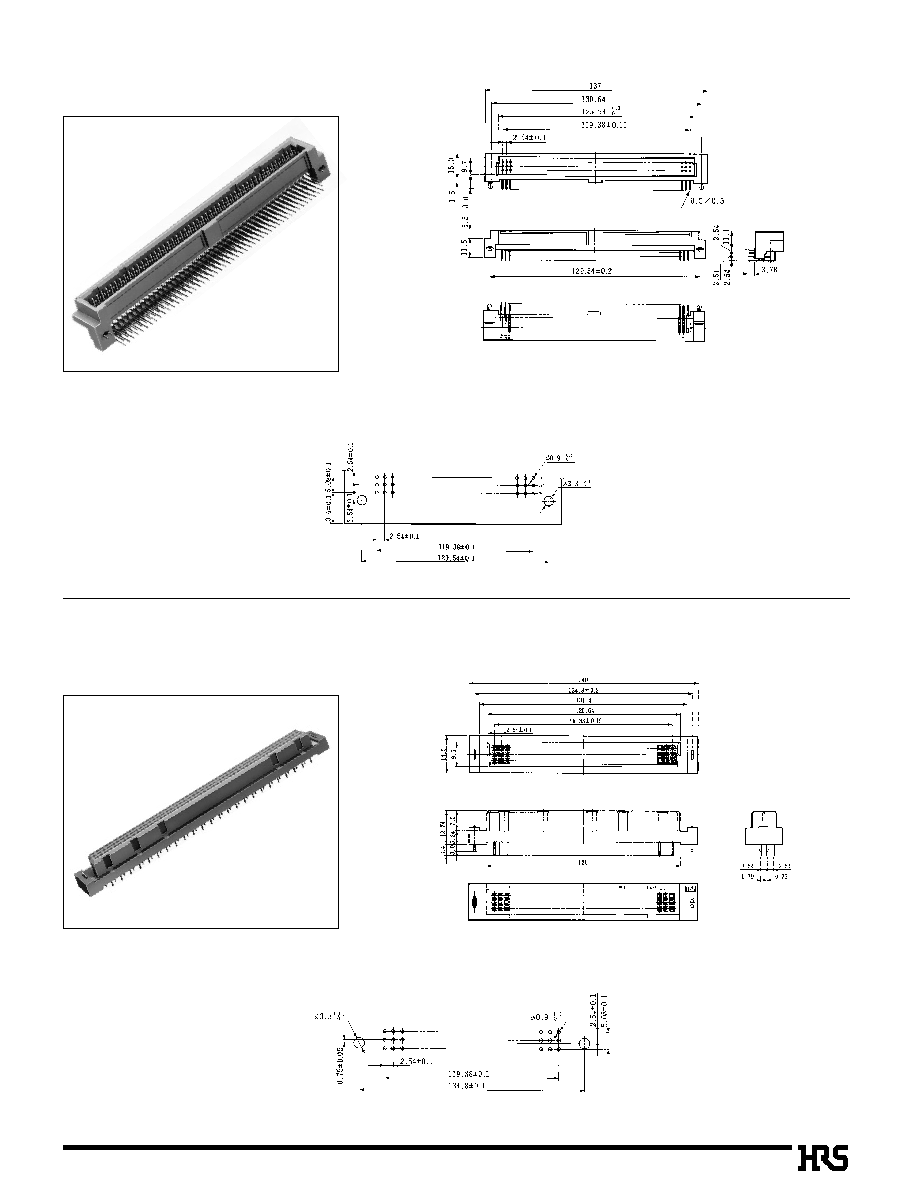
Pin Header: 3-row Right Angle Type
B
PCB mounting pattern
s
Pin Header: 3-row Right Angle Type (DIN standard type C)
The 48 contact type contains guide key grooves at 8 points.
PCN10A-
*
P-2.54DS
PCN10-
*
P-2.54DS
Unit:mm
CL No.
Part Number
583-0063-9
583-0001-1
PCN10-48P-2.54DS
PCN10-96P-2.54DS
Number of Contacts
48
96
A
B
53.36
94
.00
47.36
88
.00
C
D
38.1
0
78.74
E
48.26
88.9
0
44.61
85.25
The 48 contact type contains guide key grooves at 8 points.
Unit:mm
CL No.
Part Number
583-0064-1
583-0006-5
PCN10A-48P-2.54DS
PCN10A-96P-2.54DS
Number of Contacts
48
96
A
B
53.36
94
.00
47.36
88
.00
C
D
38.1
0
78.74
E
48.26
88.9
0
44.61
85.25

A40
B
PCB mounting pattern
s
Pin Header: Right Angle Type
B
PCB mounting pattern
s
Pin Header: Right Angle Type
PCN10A-64ACP-2.54DS
CL583-0032-5
PCN10-64ACP-2.54DS
CL583-0046-0
A41
B
PCB mounting pattern
s
Pin Header: 3-row Straight Type
B
PCB mounting pattern
s
Pin Header: 3-row Straight Type (DIN standard type R)
PCN10-48P-2.54DSA
CL583-0104-4
PCN10-96P-2.54DSA
CL583-0002-4

A42
B
PCB mounting pattern
s
Receptacle: 3-row Right Angle Type(DIN standard type R)
B
PCB mounting pattern
s
Receptacle: 3-row Right Angle Type
PCN10B-96S-2.54DS
CL583-0004-0
PCN10A-96S-2.54DS
CL583-0027-5

A43
PCN10
*
S-2.54DSA
s
Receptacle: 3-row Straight Type(DIN standard type C)
B
PCB mounting pattern
Unit:mm
CL No.
Part Number
583-0065-4
583-0003-7
583-0085-1
583-0071-7
PCN10-48S-2.54DSA
PCN10-96S-2.54DSA
PCN10-96S-2.54WA
PCN10-96S-2.54WB
Number of Contacts
48
96
96
96
A
B
54.36
95
.00
95
.00
95
.00
50
.0
90
.0
90
.0
90
.0
C
D
38.1
0
78.74
78.74
78.74
44.36
85
.00
85
.00
85
.00
B
PCB mounting pattern
s
Receptacle: 3-row Right Angle Type
PCN10B-64ACS-2.54DS
CL583-0045-7
The 48 contact type contains guide key grooves at 8 points.
*

A44
PCN10EA
*
S-2.54DSA
Note: The PCB mounting pattern is equivalent to
PCN10-
*
S-2.54DSA.
(Refer to catalog page A36.)
s
Receptacle: 3-row Straight Type(DIN standard type C)
q
With Board prefixed lock pin
B
PCB mounting pattern
s
Receptacle: Straight Type
PCN10-64ACS-2.54DSA
CL583-0044-4
Unit:mm
CL No.
Part Number
583-0195-0
583-0180-2
PCN10EA-48S-2.54DSA
PCN10EA-96S-2.54DSA
Number of Contacts
48
96
A
B
54.36
95
.00
50
.0
90
.0
C
D
38.1
0
78.74
44.36
85
.00
Note
Note: Flux prevention type
A45
s
Receptacle: 3-row Straight Type
B
PCB mounting pattern
s
Pin Header: 3-row Right Angle Type
PCN10MA-144P-2.54DS
CL583-0131-7
PCN10MA-144S-2.54DSA
CL583-0130-4
q
With Board prefixed lock pin
q
Board prefixed lock pin attached
B
PCB mounting pattern
Sequential contacts are located at 27 points up to contact
No.30~38 in both rows b and c.

A46
B
PCB mounting pattern
B
PCB mounting pattern
s
Pin Header: 4-row Right Angle Type
PCN10A-128P-2.54DS
CL583-0088-0
PCN10-128P-2.54DS
CL583-0087-7
s
Pin Header: 4-row Right Angle Type

A47
PCN10-128S-2.54DSA
s
Receptacle: 4-row Straight Type
B
PCB mounting pattern
Unit:mm
CL No.
Part Number
583-0089-2
583-0090-1
583-0091-4
PCN10-128S-2.54DSA
PCN10-128S-2.54WA
PCN10-128S-2.54WB
Number of Contacts
128
128
128
B
PCB mounting pattern
s
Pin Header: 4-row Straight Type
PCN10-128P-2.54DSA
CL583-0215-5
*

A48
B
PCB mounting pattern
s
Receptacle: 4-row Right Angle Type
PCN10B-128S-2.54DS
CL583-0333-1

A49
s
Polarizing Key
CL No.
583-0269-4
Part Number
PCN10-GK(A)
Material
PBT, black
Note: Using the polarizing key prevents connector mis-insertion in the board.
Insert the polarizing key in both connectors on the receptacle side and header side.
Insert the polarizing key so as to hit the mold bottom.

A50
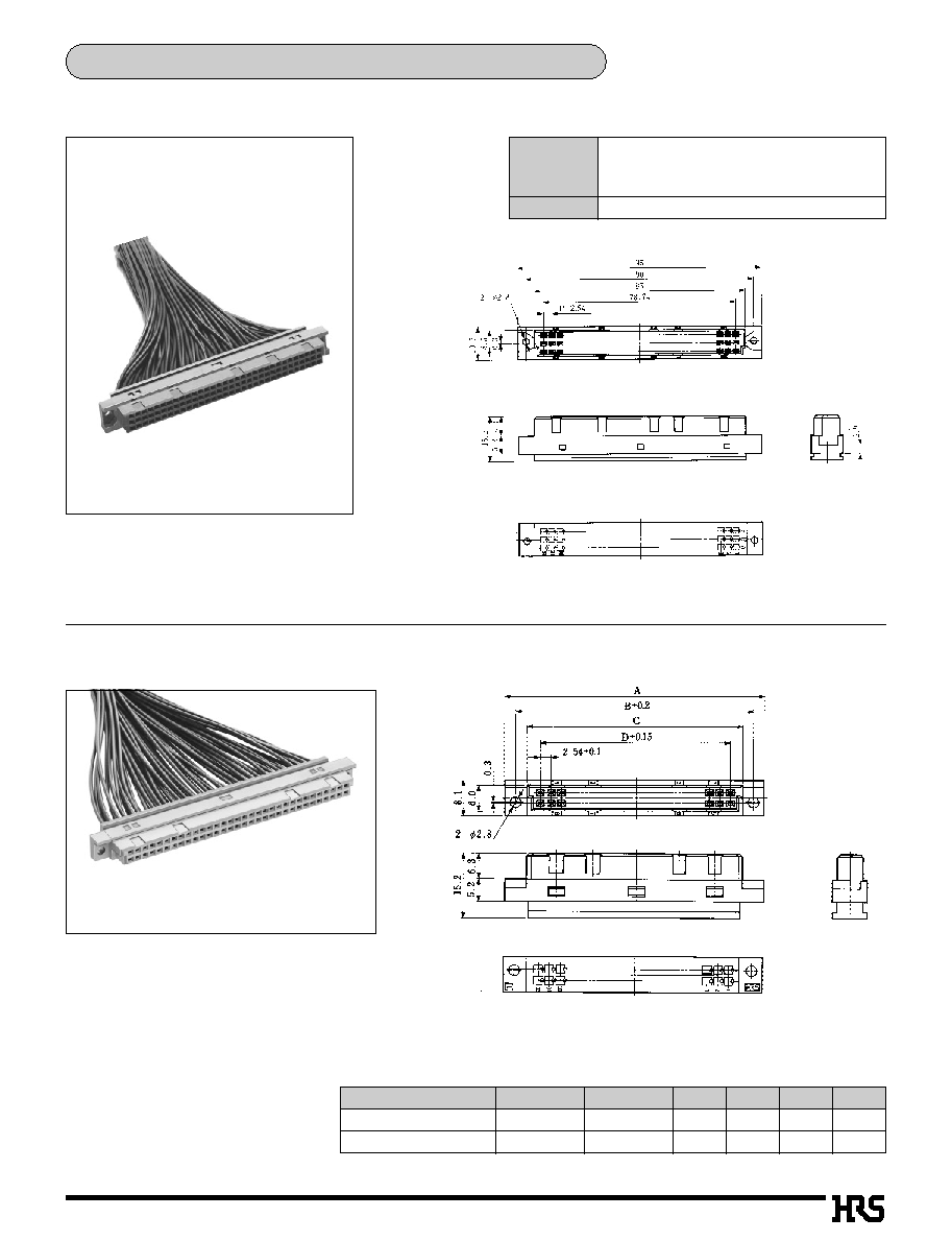
Ribbon Cable Connector Compliant with DIN Standard
s
Cable Insulation displacement Connector
PCN10-64S-2.54R
CL583-0030-0
PCN10-GPB64
CL550-0168-6
s
Insulation displacement Tool
q
Guide plate for insulation
displacement + pressing block
q
Hi-Flex connection press
CL No.
550-0082-2
Part Number
Hi-Flex connection press HHP502
Height
440mm
Width
160mm
Depth
350mm
Weight
13kg
A51
Crimping Connector Compliant with DIN Standard
s
3-row Type
PCN10-96S-2.54C
CL583-0100-3
s
2-row Type
CL No.
583-0241-5
583-0243-0
Part Number
PCN10-20S-2.54C
PCN10-64S-2.54C
Number of Contacts
20
64
A
39.12
95
.00
B
34.12
90
.00
C
D
29.12
85
.00
22.86
78.74
Unit: mm
Current rated
Voltage rated
ID type
1A
2A
Crimping type AWG#26
2A
AWG#28
�
30
1A
300V AC
(Crimping type 200V AC)
(
)
PCN10-
*
S-2.54C

A52
s
Manual Crimping Tool
q
Crimping Contact
q
PCN10-2630SC (Full Gold plated)
CL583-0102-9
q
PCN10-2226SC (Selective Gold plated)
CL583-0216-8
q
Crimping tool
q
PCN10-TA2630HC (PCN10-2230SC)
CL550-0163-2
q
PCN10-TA2226HC (PCN10-2226SC)
CL550-0218-2
q
PCN10-2630SC: AWG#26 to #30
100pcs per bag
q
PCN10-2226SC: AWG#22 to #26
100pcs per bag
s
Automatic Crimping Tool
Item
Part Number
CL No.
Applicable Contact
Crimping tool unit
Applicator
CM-105
AP105-PCN10-2226S
AP105-PCN10-2630S
901-0005-4
901-3506-6
901-3508-1
------------------
PCN10-2226SCF
PCN10-2630SCF
s
Contact Extraction Tool
Applicable Cable
CL No.
550-0282-1
Part Number
PCN10-PO
A53
B
PCB mounting pattern
s
Receptacle: 3-row Straight Type
B
PCB mounting pattern
s
Pin Header: 3-row Right Angle Type
PCN10MC-96S-2.54DSA
CL583-0169-0
PCN10MC-96P-2.54DS
CL583-0120-0
Circuit Protection Function Type

A54
PCN10MC-
*
h-2.54DS
PCN10MC-
*
P-2.54DS
s
Pin Header: 2-row Right Angle Type
B
PCB mounting pattern
Unit:mm
B
PCB mounting pattern
s
Receptacle: 3-row Wrapping Type
PCN10MC-96S-2.54WB
CL583-0119-1
CL No.
Part Number
583-0211-4
583-0212-7
PCN10MC-
0
64P-2.54DS
PCN10MC-100P-2.54DS
Number of Contacts
A
64
100
94
.0
139.72
B
85.35
131.07
C
78.74
124.46
D
88.9
134.62
A55
PCN10MC-
*
S-2.54DSA
s
Receptacle: 2-row Straight Type
B
PCB mounting pattern
Unit:mm
CL No.
Part Number
583-0213-0
583-0214-2
PCN10MC-
0
64S-2.54DSA
PCN10MC-100S-2.54DSA
Number of Contacts
A
64
100
95
.0
140.72
B
90
.0
135.72
C
85
.0
130.72
D
78.74
124.46
Note 2:
(64 contacts): The sequential contacts are located at 27 points
of 1 to 4 and 26 to 32 in both rows a and b.
(100 contacts): The sequential contacts are located at 22 points
of 1 to 4 and 44 to 50 in both rows a and b.

A56
B
PCB mounting pattern
B
Application Pattern
s
Stacking Plug
Stacking Connector
Unit: mm
C
Part Number
CL No.
B
D
E
A
Number of Contacts
16
20
24
32
44
50
16
20
24
32
44
50
16
20
24
32
44
50
16
44
50
16
24
44
50
37.92
43
.00
48.08
58.24
73.48
81.1
0
37.92
43
.00
48.08
58.24
73.48
81.1
0
37.92
43
.00
48.08
58.24
73.48
81.1
0
37.92
73.48
81.1
0
37.92
48.08
73.48
81.1
0
33.02
38.1
0
43.18
53.34
68.58
76.2
0
33.02
38.1
0
43.18
53.34
68.58
76.2
0
33.02
38.1
0
43.18
53.34
68.58
76.2
0
33.02
68.58
76.2
0
33.02
43.18
68.58
76.2
0
24.39
29.47
34.55
44.71
59.95
67.57
24.39
29.47
34.55
44.71
59.95
67.57
24.39
29.47
34.55
44.71
59.95
67.57
24.39
59.95
67.57
24.39
34.55
59.95
67.57
17.78
22.86
27.94
38.1
0
53.34
60.96
17.78
22.86
27.94
38.1
0
53.34
60.96
17.78
22.86
27.94
38.1
0
53.34
60.96
17.78
53.34
60.96
17.78
27.94
53.34
60.96
29.8
24.8
19.8
39.8
34.8
4.42
40
F
3.44
3.36
3.28
3.30
G
35
30
25
45
PCN10H-16P-2.54DSA
PCN10H-20P-2.54DSA
PCN10H-24P-2.54DSA
PCN10H-32P-2.54DSA
PCN10H-44P-2.54DSA
PCN10H-50P-2.54DSA
PCN10HA-16P-2.54DSA
PCN10HA-20P-2.54DSA
PCN10HA-24P-2.54DSA
PCN10HA-32P-2.54DSA
PCN10HA-44P-2.54DSA
PCN10HA-50P-2.54DSA
PCN10HB-16P-2.54DSA
PCN10HB-20P-2.54DSA
PCN10HB-24P-2.54DSA
PCN10HB-32P-2.54DSA
PCN10HB-44P-2.54DSA
PCN10HB-50P-2.54DSA
PCN10HC-16P-2.54DSA
PCN10HC-44P-2.54DSA
PCN10HC-50P-2.54DSA
PCN10HD-16P-2.54DSA
PCN10HD-24P-2.54DSA
PCN10HD-44P-2.54DSA
PCN10HD-50P-2.54DSA
583-0227-4
583-0157-0
583-0425-8
583-0161-8
583-0164-6
583-0401-0
583-0228-7
583-0158-3
583-0426-0
583-0162-0
583-0165-9
583-0402-2
583-0229-0
583-0159-6
583-0427-3
583-0163-3
583-0166-1
583-0403-5
583-0397-4
583-0399-0
583-0404-8
583-0398-7
583-0429-9
583-0400-7
583-0405-0
Note: Please note that the above series can not mate with PCN10EA series.
*
*
*

A64
B
Application Pattern
q
Vertical Connection
q
2-row type
'
: Mounting hole center
C.L. :Center line

A65
q
3-row type
'
: Mounting hole center
C.L. :Center line
48
contacts:
17.9
48
contacts:
1
9.09
48
contacts:
1
9.09

A66
q
3-row 144 Contact type
q
4-row type
48
contacts:
1
9.09
'
: Mounting hole center
C.L. :Center line

A67
B
Application Pattern
q
Horizontal Connection
q
2-row type
'
: Mounting hole center
C.L. :Center line
q
4-row type

A68
q
3-row type
'
: Mounting hole center
C.L. :Center line
48
contacts:
19.09

A69
B
Application Pattern
q
Horizontal Connection
q
2-row type
q
4-row type
q
3-row type
48
contacts:
1
7.9
48
contacts:
1
7.9
'
: Mounting hole center
C.L. :Center line