
1
2mm Hard Metric Connector
PCN21 Series
IEC 61076-4-101-compliant
NEW
2002.11
Style A
Style C
Compact PCI P2/J2, P3/J3 equivalent
Style B
s
Applications
Switchboards, transmission systems, Celluler base
stations, industrial computer boards, measuring
instruments, control equipment
s
Product varieties
(see page 2 for details)
s
Features
1. IEC compliant
This 2 mm Hard Metric (HM) Connector complies with
IEC 61076-4-101. As specified by IEC Standards, 3
types are available: Style A (110 contacts), Style B (125
contacts), Style C (55 contacts) and Style M.
2. Many Variations
Products equivalent to Compact PCI standard P2/J2 (110
contacts), P3/J3 (95 contacts) and AB Type (125
contacts) are available.
3. Press-fit connection
Connectors of this series, headers and receptacles, are
designed for press fit connection.
4. Both-side, two-point contact
Receptacles feature two-point contact design for high reliability.
5. Ground Connection Supported
Contacts are lined up in rows z a b c d e f. Five rows (a
b c d e) are used for signals and two rows (z f) can be
added at both sides for use as ground.
6. 3-Stage Sequence Supported
There are 3 types of coupling portion contact lengths for
the header which permits a 3-stage sequence.
7. Coding Keys Can Be Mounted
Coding keys can be attached to style A for the purpose
of preventing incorrect insertion of the connector.
8. Two different platings are available on PCB
leads
Gold plating and Tin plating are available on PCB leads.

2
s
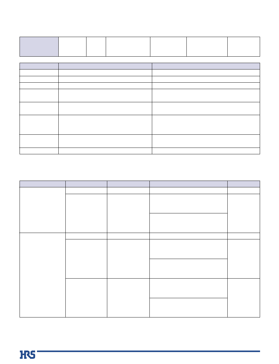
PCN21 Series Seletion Chart
Header
c
onnector
(
Back
Wiring
Board
s
ide
(
BWB)
male
connector)
Receptacle
connector
(
Package
side
female
connector)
Without
g
round
p
late
Style A
Style B
Compact PCI
P2/J2 equivalent
Compact PCI
P3/J3 equivalent
Style C
IEC 61076-4-101 compliant
Short
p
in
type
With
ground
p
late
Without
g
round
terminal
With
ground
terminal
Long
p
in
type
Without
g
round
terminal
With
ground
terminal
With
top
ground
plate
Bottom
g
round
p
late
PCN21
*
-110PA-2PF-G PCN21
*
-125PB-2PF-G PCN21
*
-55PC-2PF-G PCN21
*
-110PB-2PF-G PCN21
*
-95PB-2PF-G
PCN21
*
-110PA-2PF PCN21
*
-125PB-2PF
PCN21
*
-55PC-2PF
PCN21
*
-110PB-2PF
PCN21
*
-95PB-2PF
PCN21
*
-110PA-2W
PCN21
*
-95PB-2W
PCN21
*
-110PB-2W
PCN21
*
-55PC-2W
PCN21
*
-125PB-2W
PCN21
*
-95PB-2W-G
PCN21
*
-110PB-2W-G
PCN21
*
-55PC-2W-G
PCN21
*
-125PB-2W-G
PCN21
*
-110PA-2W-G
PCN21
*
-95SB-2PF
PCN21
*
-110SB-2PF
PCN21
*
-55SC-2PF
PCN21
*
-125SB-2PF
PCN21
*
-110SA-2PF
PCN21
*
-110SA-2PF-G PCN21
*
-125SB-2PF-G PCN21
*
-55SC-2PF-G PCN21
*
-110SB-2PF-G PCN21
*
-95SB-2PF-G
PCN21
*
-SB2-G
PCN21
*
-SB1-G
PCN21
*
-SC-G
PCN21
*
-SB-G
PCN21
*
-SA-G
P5
P6
P7
P6
P6
P6
P6
P7
P6
P5
P5
P6
P7
P6
P6
P6
P6
P7
P6
P5
P10
P11
P12
P11
P11
P10
P11
P12
P11
P11
P15
P15
P15
P15
P15
*
A∑∑∑PCB leads : Gold plating
*
B∑∑∑PCB leads : Tin plating
0
Standards
Item

3
Series name: PCN21
B
Product construction
Bottom ground plate for receptacle
s
Ordering information
3
3.7
13
14.5
16
5.3
6.8
8.3
Row f: Top ground plate
Row z: Bottom ground plate
PKG
BWB
PCN21*-S*-G
Row
f
e
d
c
b
a
z
Row
a b c d e f
A ground plate is joined with the f row.
Connector
Positioning peg (Applicable to receptacle styles A and C only)
Nil : With peg
A
: Without peg
2
3
7
9
PCN 2 1
*
-
*
P A
*
- 2 PF - G (01)
1
4
6
7
2
3
5
8
10
9
8
Series name
: PCN 21
A∑∑∑PCB leads
: Gold plating
B∑∑∑PCB leads
: Tin plating
No. of contacts : 55, 95, 110, 125
1
Terminal shape
PF : Press-fit short pin
W
: Press-fit back plane
Ground
Nil : Without ground terminal
G
: With ground terminal
Contact area gold plating thickness
Nil : 0.8
µ
m
(01) : 0.2
µ
m
Contact pitch: 2 mm
6
Connector classification
P: Pin header
S: Receptacle
IEC type
A : IEC 61076-4-101 Style A
B : IEC 61076-4-101 Style B
C : IEC 61076-4-101 Style C
M : IEC 61076-4-101 Style M
AB : Compact PCI AB type equivalent
For Compact PCI P2/J2, P3/J3 equivalent,
the IEC type should be style B.
PCN 2 1
*
- S A - G
1
4
2
3
5
A∑∑∑PCB leads : Gold plating
B∑∑∑PCB leads : Tin plating
Connector classification: for receptacle use
1
Applicable connectors
A : for PCN21
*
-110SA-2PF-G
B : for PCN21
*
-125SB-2PF-G
C : for PCN21
*
-55SC-2PF-G
B1: for PCN21
*
-110SB-2PF-G
B2: for PCN21
*
-
0
95SB-2PF-G
Ground
2
3
5
q
Header
q
Receptacle
Rows f and z are ground terminals.
PCN21
*
-
*
P
*
-2PF (W) has no ground terminal
PCN21
*
-
*
P
*
-2PF (W)-G has ground terminal
PCN21
*
-
*
S
*
-2PF has no top ground plate
PCN21
*
-
*
S
*
-2PF-G has top ground plate
PCN21
*
-S
*
-G has bottom ground plate only
10
3
4
5
4
)
(
4
s
Product Specifications
s
Materials
Rating
1.5A
AC 300V
Current rating
Voltage rating
≠55
Á
to +85
Á
95% RH max.
(No condensation)
Operating temperature
Operating humidity
≠10
Á
to +60
Á
40% to 70% RH
Storage temperature
Storage humidity
100 V DC
750 V rms AC for 1 min
0.1 A
40
±
2
Á
, 90 to 95% RH, duration 96 h
Frequency 10 to 500 Hz, amplitude of 0.35 mm in 3
directions, 50m/s
2
acceleration, 10 cycles each
5 cycles
( -55
Á
for 30 min, 15 to 30
Á
for 5 min max, +125
Á
for
30 min, 15 to 30
Á
for 5 min max. )
Ambient temperature + 125
Á
, 16 h
500 cycles
PCN21A
Contact area : Nickel base, gold plating
Mounted area: Nickel base, solder plating
PCN21B
Contact area: Nickel base, gold plating
PCB leads
: Nickel base, tin plating
10
4
M ohms
No flashover or breakdown
30 m ohms max.
Contact resistance:40 m ohms max.
Insulation resistance: 10
3
M ohms min.
No damage, cracks or parts looseness
Contact resistance:40 m ohms max.
Insulation resistance: 10
3
M ohms min.
Contact resistance:40 m ohms max.
Contact resistance: 40 m ohms max.
Insulation resistance: 10
3
M ohms min.
No electrical discontinuity for 1
µ
s min.
1.Insulation resistance
2.Withstanding voltage
3.Contact resistance
4.Vibration
5.Damp heat
6.Rapid change of
temperature
7.Heat resistance
8.Operation life
Item
Requirements
Test Conditions
Remarks
UL94V-0
≠≠≠≠≠≠≠
UL94V-0
≠≠≠≠≠≠≠
≠≠≠≠≠≠≠
Part
Material
Finish
PBT
Phosphor bronze
PBT
Phosphor bronze
Insulator
Terminal
Insulator
Terminal
Shield
Phosphor bronze
Product
Header
Receptacle
Gray
PCN21A
Contact area: Nickel base, gold plating
PCB leads
: Nickel base, gold plating
PCN21B
Contact area: Nickel base, gold plating
PCB leads
: Nickel base, tin plating
Gray
PCN21A
Contact area: Nickel base, gold plating
PCB leads
: Nickel base, gold plating
PCN21B
Contact area: Nickel base, gold plating
PCB leads
: Nickel base, tin plating

5
s
Header (Style A) [BWB-side male connector]
B
Recommended PCB mounting pattern
Product No.
PCN21
*
-110PA-2PF
PCN21
*
-110PA-2PF-G
PCN21
*
-110PA-2W
PCN21
*
-110PA-2W-G
A
110
154
110
154
No. of contacts
5
7
5
7
Mounted area
Short pin
Long pin
ÿ2
+0.1
0
A- ÿ0.6 ±0.05
48 ±0.1
20 ±0.1
20 ±0.1
2±0.05
12
±0.05
2
±0.05
Row No.
Contact No.
1
11
15
25
..........................
...........................
f
e
d
c
b
a
z
1
15.4
...............................
..............................
1
A
5
2
>
P B T
<
2
12
Row No.
Contact No.
25
15
11
20
2
20
48
ÿ1.9
3.7
49.95
( 0.55 )
( 0.4 )
2
1
f
e
d
c
b
a
z
< Short pin >
< Long pin >
16
13
13.45
3.5
5.3
8.3
3
1
Through hole
Drilling diameter
:
ÿ
0.7
±
0.02
Finishing diameter
:
ÿ
0.6
±
0.05
Plating
: Cu 25
µ
min.
2
For 5-row type, row f and z are unnecessary.
3
Board thickness
: 1.6 to 5.6 mm
*
A∑∑∑PCB leads : Gold plating
*
B∑∑∑PCB leads : Tin plating
0