D31
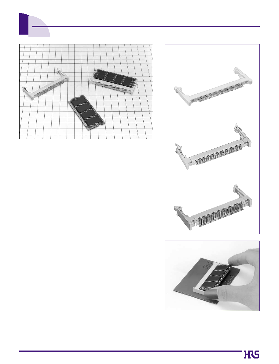
0.635mm Pitch S.O. DIMM Socket
SX1 Series
s
Features
1. 72pos. Small Outline DIMM Socket
SX1 series is a 0.635mm pitch horizontal SMT type socket
applicable to
Small Outline DIMM standardized in JEDEC.
The size is about half as large as the conventional 72 contacts
DRAM SIMM socket.
Corresponding to double density (both surfaces), this socket realizes
high functionality and density of the module board.
2. Variation in Mounting Height
Three grades of variation are available for the mounting height.
3. Easy Insertion and Extraction of Module Board
One-touch operation to insert the module board slantly and push it
downward.
Widen latches right and left, and the module board will be
automatically raised.
This mechanism allows easy automatic insertion and extraction.
4. Achieve High Performance
This socket achieves high performance by the wiping effect in the
insertion and the unique press-fit face contact.
5. Insertion and Extraction Operation with Click
Sensibility
The unique mold twin-latch allows excellent insertion and extraction
operation with a sensible click.
s
Applications
Personal computers, business equipment, Measuring instrument,
telecommunication equipment, FA, game, etc.
q
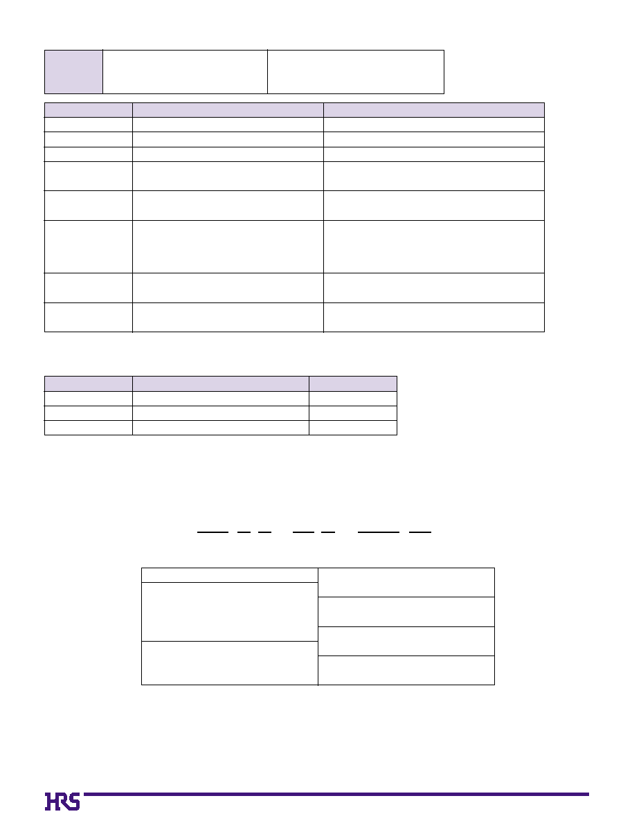
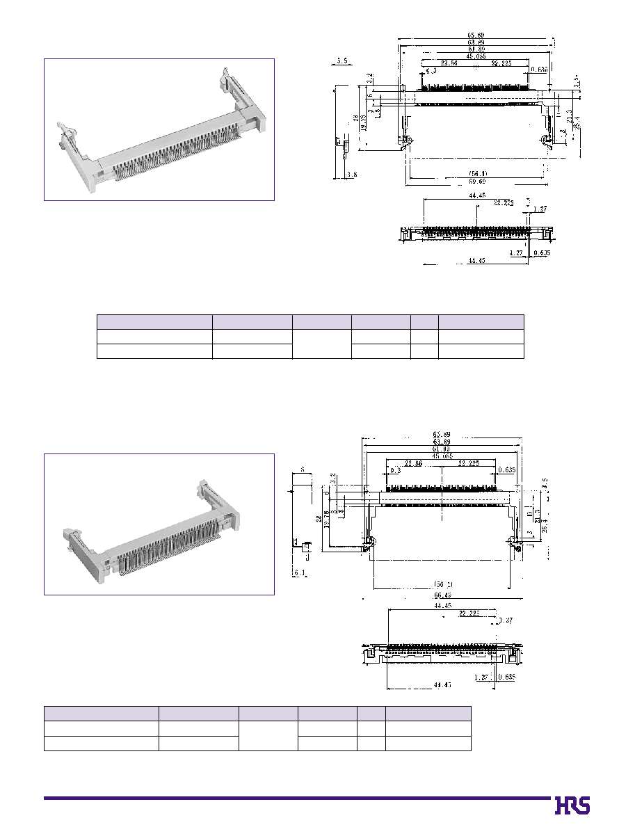
Standard Type (Mounting Height: 5.5mm)
q
Low Profile Type (Mounting Height: 4.0mm)
Variation in Mounting Height
q
High Profile Type (Mounting Height: 8.0mm)
Easy Insertion and Extraction Operation of
Module Board
D32
Part
Material
Finish
Contact
Phosphor copper
Selictive Gold plating
Insulator PA(UL94V-0)
----------
Metal Fitting
Phosphor copper
Solder plating
s
Product Specifications
s
Material
Rating
Current rating
Voltage rating
Operating Temperature Range
-55
�
+85
�
125V AC
0.5A
Operating Humidity Range -55
�
to +85
�
Item
1. Contact Resistance
2. Insulation Resistance
3.
Withstanding voltage
4. Vibration
5.
Humidity
(Steady state)
6. Temperature
Cycle
7.
Durability
(Insertion/withdrawal)
8. Salt spray
35m
ohms
min.
100mA
1000M
ohms
min.
250V DC
No flashover or insulation breakdown.
250V AC / 1 minute
No electrical discontinuity of 1�s or more
Frequency: 10 to 55 Hz, single amplitude of 0.75 mm,
50 minutes in each of the 3 directions.
Contact resistance: 55m
ohms
max.
Insulation Resistance: 1000M
ohms
min
96 hours at temperature of 40�
and humidity of 90% to 95%
Contact resistance: 55m
ohms
max.
Insulation Resistance: 1000M
ohms
min:
5 cycles under following condition;
Temperature
: -55
+5 to 35
+85
+5 to 35
�
Time
:
-
30
10 to 15
+
30
10 to 15
Contact resistance: 55m
ohms
max.
Contact resistance: 55m
ohms
max.
30 cycles
Exposed to density 5% salt water for 48 hours
Specification
Condition
SX1 C A - 72 S - 0.635 SH
q
r
u
e
w
t
y
q
Series Name
: SX1
w
Mounting Height
B : Standard type (Height: 5.5mm)
C : High profile type (Height: 8.0mm)
E : Low profile type (Height: 4.0mm)
e
DIMM Key
None : 3.3V type
A
: 5V type
r
Number of Contacts
: 72
t
Contact Type
: Female contact
y
Contact Pitch
: 0.635mm
u
Contact type
SH : SMT type
s
Ordering Information
D33
s
Standard Type
s
High Profile Type
CL No.
Number of Contacts
Part Number
Remarks
Key
D
530-0018-9
72
SX1B-72S-0.635SH
Selective gold plating
3.3V Type
3.1
530-0019-1
SX1BA-72S-0.635SH
Selective gold plating
5V Type
5.4
Note 1: The tube packaging product is provided for products marked with *. In order to designate the
tube package product, add (20) to the tail of the Part Number (Delivery unit: 20 pcs per set)
Note 2: The 3.3V and 5V keys correspond to the Small Outline DIMM key.
CL No.
Number of Contacts
Part Number
Remarks
Key
D
530-0003-1
72
SX1C-72S-0.635SH
Selective gold plating
3.3V Type
3.1
530-0004-4
SX1CA-72S-0.635SH
Selective gold plating
5V Type
5.4
Note 2: The 3.3V and 5V keys correspond to the Small Outline DIMM key.

D34
s
Low Profile Type
B
Recommended Temperature Profile
q
IR Reflow: Recommended Temperature Profile (Up to second reflow)
q
Manual Soldering
Soldering iron temperature: 300
�
10
�
Manual soldering time: 3 seconds max.
This temperature profile is recommended.
The temperature may be slightly changed according to solder
paste types and amount.
q
Applicable Conditions
Reflow system : IR reflow
Solder
: Paste type 63 Sn/37 Pb
(Flux content 11 wt%)
Test board Glass epoxy 110mm x 85mm x 1.6 mm
Metal mask thickness: 0.15 mm
Recommended temperature profile.
The temperature may be slightly changed according to the solder paste type and amount.
5 seconds max.
Preheating time,
80 seconds
Soldering time,
30 seconds
Naturally
exposed
(Time)
250
240
235
220
200
180
150
140
Temperature
(�)
CL No.
Number of Contacts
Part Number
Remarks
Key
D
530-0006-0
72
SX1E-72S-0.635SH
Selective gold plating
3.3V Type
3.1
530-0007-2
SX1EA-72S-0.635SH
Selective gold plating
5V Type
5.4
Note 2: The 3.3V and 5V keys correspond to the Small Outline DIMM key.
D35
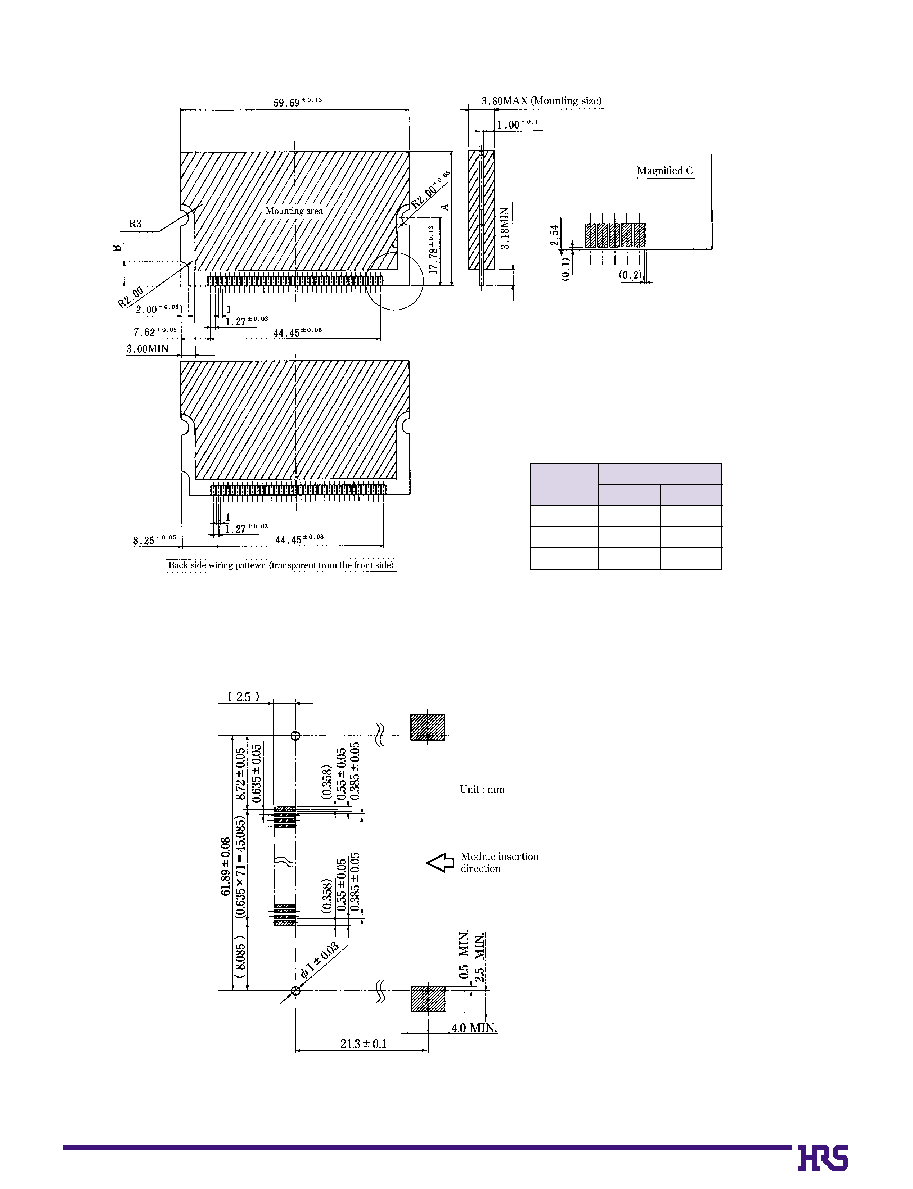
5V
3.3V
B
A
25.40
31.75
38.10
3.18
3.18
3.18
6.35
6.35
6.35
B
Recommended Module Board Dimensions
B
PCB mounting pattern
Unit: mm
D36
B
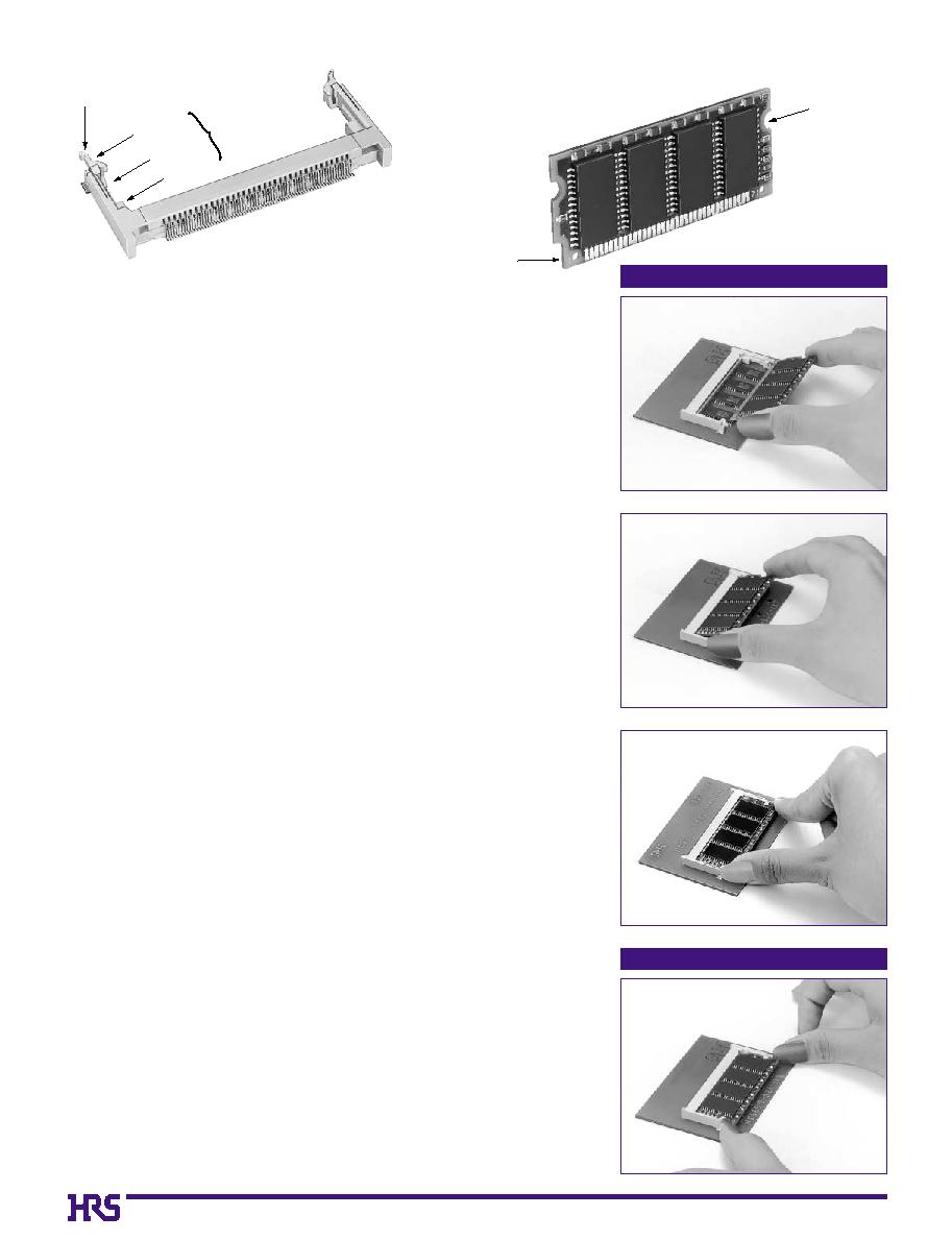
Precautions for use
Procedures for Board Extraction
e
w
Procedures for Board Insertion
q
Procedures for Board Insertion
1. Adjust the socket polarizing key and the board key to the same direction.
2. Insert the board obliquely. Moreover, lay the board in parallel to the opening at
angle of 20� to 30� , and softly insert the board so as to hit the socket bottom.
Stopping insertion halfway will result in improper insertion.
3. Applying the board side notch in parallel to the socket bottom so that the board
position cannot be displaced, press the board side notch up, and fix it to the latch
portion at both socket edges. Press the board side notch, and release the notch
with a snap "click" tone, if the printed board exceeds the latch claw head.
3.
With this action, the board has been completely installed in the socket. At this
time, pressing force is equivalent to the extent to turn on the electric product
switch. If the stronger pressing force is needed, check whether the direction and
depth to insert the board is adequate or not, and then re-push the board.
Procedures for Board Extraction
Standard type and high profile type
Apply the thumb nail to the latch knob at both socket edges. Forcibly widen
the latch knobs to right and left ways, and release the latch. Then, draw
the board out along an angle where the board is raised.
Low profile type
Press the top of the latch unit down with fingers to release the latch, and
directly draw the board out.
Cautions
1. The latch has strength enough to endure. However, if force is applied according
to other operation methods instead of the Procedures for Handling Sockets, or if
further force is given in the state where the module board is raised, products
could be damaged. Be sure to observe the Procedures for Handling Sockets.
2. The board is designed in compliance with JEDEC "Small Outline DIMM (Dual
Inline Memory Module". However, if the board is used instead of the
recommended module board, or if the mounting product is used for other devices
than DRAM memory IC, troubles due to vibration or other failures could occur. If
needed, consult the HRS company.
3. The above illustration shows SX1B.
4. The recommended module board pad or sharp angle edges could cause failure
in contacts. Therefore, it is recommended to offset the tie-bar from the center
line, set the internal pad (0.1mm), or remove sharp corners or burrs according to
the recommended sizes.
5. Don't provide the external contact surface of the module board with the
convex/concave and chamfer areas at both edges. Comply with the
recommended sizes.
6. When the board is mounted or housing is installed, if warpage or flexure has
occurred, an excessive load could cause changes in the solder bonding area
and the strength. Check individual conditions.
Side notch
Key
Latch knob
Latch claw
Latch section
Latch arm
Polarizing key