D6
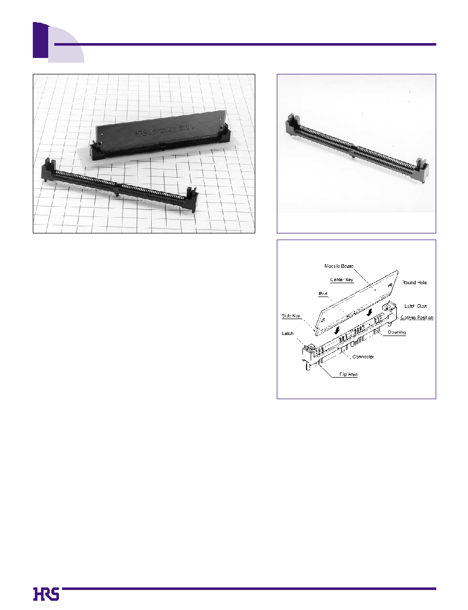
1.27mm Pitch SIMM Socket
SX3 Series
s
Features
1. JEDEC Standard MO-116
This socket is suitable to JEDEC standard 1.27mm pitch 72pos.
memory module PC board.
2. Achieves High Reliability
New concept "mold latch system" achieves high reliability for safe
handling.
3. Greatly Improves Operation Durability
The mold latch system has greatly improved the operation durability
using the FEM analysis.
4. Achieves High Performance
Contacts achieves high reliability in contact with smooth rolling
areas.
5. Secures Stable Contact Areas
The contact floating mechanism and structure to reduce the board
warpage secures stable contact areas.
SX3LE-72S-1.27DSA
s
Applications
Note PC, workstations, business machines, measuring instruments, etc.
D7
s
Product Specifications
Rating
Operating Temperature Range
Voltage rating
Current rating
-55
Á
to 85
Á
100V AC
1A
Storage Temperature Range
-55
Á
to +85
Á
Item
1. Contact Resistance
2. Insulation Resistance
3. Withstanding voltage
4.Vibration
5. Humidity
(Steady state)
6. Temperature
Cycle
7. Durability
(Insertion/withdrawal)
8. Salt spray
20m
ohms
min.
100mA DC
1000M
ohms
min.
500V DC
No flashover or insulation breakdown.
500V AC / 1 minute
No electrical discontinuity of 1µs or more
Frequency: 10 to 55 Hz, single amplitude of 0.75 mm,
50 minutes in each of the 3 directions.
Contact resistance: 40m
ohms
max.
Insulation Resistance: 1000M
ohms
min.
96 hours at temperature of 40Á and humidity of 90% to 95%
Contact resistance: 40m
ohms
max.
Insulation Resistance: 1000M
ohms
min.
Tested for 5 cycles under following condition;
Temperature : -55
°
+5 to 35
°
+85
°
+5 to 35
Á
Time
:
-
30
°
10 to 15
°
+
30
°
10 to 15 minutes
Contact resistance: 40m
ohms
max.
25 cycles
Contact resistance: 40m
ohms
max.
Exposed to density 5% salt water for 48 hours
Specification
Condition
s
Material
Part
Contact
Insulator
Phosphor copper
PBT
UL94V-0
Selective gold plating
Material
Finish
s
Ordering Information
SX3 LE - 72 S - 1.27 DSA
1
2
3
4
5
6
Series Name: SX3
1
Contact Pitch: 1.27mm
5
6
Contact type (row space x lead length)
DSA: 2.54mm x 3.1mm
Polarizing Key: LE: Left key
2
Number of Contacts: 72
3
Contact Type: Female contact
4
D8
s
Left Key Type
B
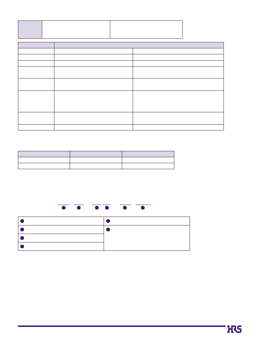
Recommended Module Board Dimensions
CL No.
Part Number
Contact Plating Spec.
Key
Number of Contacts
530-0210-6
SX3LE-72S-1.27DSA
Contact: Gold flash
Left
72
Note 1. The key corresponds to the JEDEC MO-116 polarizing key.
Note 2. When the 25.4mm height module board is used, the module board mounting height is 28mm.
B
PCB mounting pattern
q
The module board is based on the JEDEC (MO-116) standard board.
D9
s
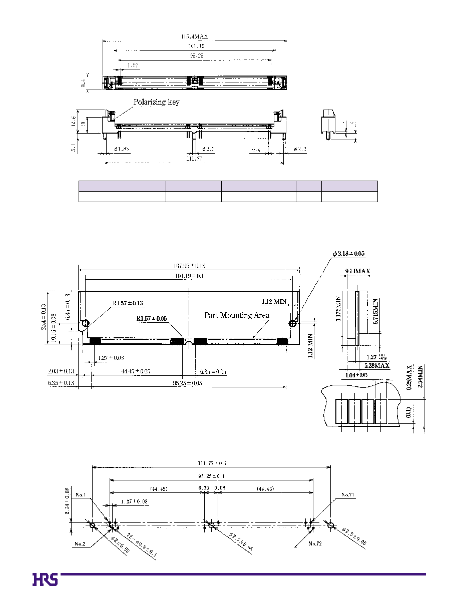
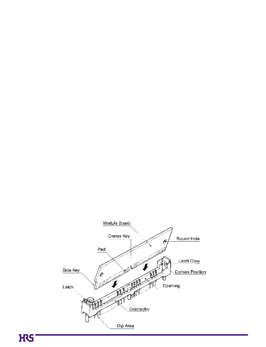
Operating Instruction
[Procedures for Board Insertion]
1. Adjust the socket polarizing key and the board key to the same direction.
2. Insert the board slantly. Moreover, lay the board at about 45
∞ a
angle, and softly
insert the board so as to hit the socket bottom. Stopping insertion halfway will
resultin improper insertion.
3. Raise the board, which has been inserted, and fix it to the latch position at both
ends of the socket.
3.
As soon as the board has passed through the latch claw head, a "click" tone is
heard. With such a click, release hands. With this procedure, the board has
been completely installed in the socket. At this time, the pressing force is
equivalent to the extent of turning on an electric product switch. If the more force
is needed, check whether the direction and depth to insert the board is adequate
or not, and then re-push the board.
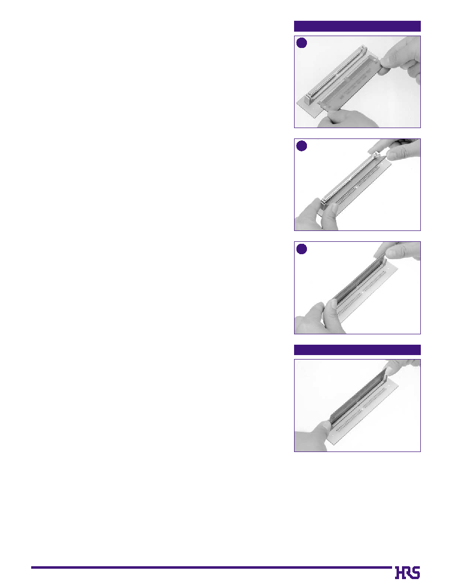
[Procedures for Board Extraction]
3.
Apply the thumb nails to the latch knobs at both socket ends. Forcibly widen the
latch knob to right and left ways and release the latch. Then, draw the board out
along the angle where the board is raised.
Cautions
1. The latch has strength enough to endure. However, if force is applied according
to other operation methods instead of the Procedures for Handling Sockets,
products could be damaged.
2. The board is designed in compliance with JEDEC 72 SIMM . However, if other
boards (specific board style, weight) are used instead of the recommended
module board or if the mounting devices are used the other than memory IC,
troubles due to vibration or other failures could occur. Confirm individual
conditions.
3. Acute angles at pad edges of recommended module boards could cause failure
in contacts. Therefore, it is recommended to offset the tie-bar (0.1mm) from the
center line, set the internal pad, or remove sharp corners or burrs according to
the recommended size ranges.
4. Stand-off is provided for measures to prevent flux rise, but resin sealing is not
done. Confirm individual conditions.
5. If strong heat is concentrated on the product, the product will be deformed due
to strength. If required, consult HRS company.
6. Use alcohol-based flux solvent, which is not affected by subject chemical
reaction.
7. For sharp temperature variation or other reasons, if dews occur on the products,
the product quality will be degraded. Take care of storage and applications.
8. Don't provide convex or concave portion at external edges of the module board,
or and chamfer areas at both edges. Comply with the recommended sizes.
9. When two or more products are arranged for use, engage the module board in
the manner to set the insertion side toward yourself and mount it sequentially
from the depth.
Procedures for Board Insertion
1
Procedures for Board Extraction
2
3
D10
10. It is recommended to specify an eccentricity between external edge (107.95) center and key (R1.57) center on the
recommended module board to 0.1 maximum.
11. Insert the module board in parallel to the connector opening. If a strong resistance is perceived, re-insert the board. Note: the
forced insertion could cause failure in the products.
12. If the connector is mounted horizontal to the direction, it is recommended to turn up the side to install the module board.
13. When two or more boards are arranged for use, it is recommended to specify the mounting pitch to 10.16mm or more. If the
less than 10.16mm pitch is used, confirm individual conditions.
14. The dip portion tip is considered for safety, the tip is slimmed for enhancement of mountability. Be careful for handling dip
portions.
15. Check the matching with individual module board, and confirm no problem.
16. The mounting height will increase under conditions of flow solder, board warpage, etc. Referring to the described values, check
and use this product according to actual equipment.
17. Since this product does not correspond to reflow, check individual conditions for application.
18. Since this product is not specified for active cable insertion and extraction, be sure to insert or extract the memory module in the
condition where unit power is turned off.
19. When the module board is engaged, check that the both board edges hook in the latch claws on the both sides, while left and
right convex portions of the connector are firmly inserted in the round holes of module on both sides. Inadequate engagement
(engagement as not described precedingly) could cause fuming, breakage, damage or contact failure in products. Take
particular care for the insertion.
20. In order to install the module board, avoid the insertion to hold and rotate either board end only. For the board won't hook in the
latches on the both side, or excessive force is applied to the connector or module board, which could cause failure or breakage
of the product. Push the upper sides at both board edges at a time, and rotate the board so as to uniformly apply force to the
latches.
21. If the memory module is not engaged in the board and exposed, dust will adhere to the opening area, which could cause
malfunction, contact failure or damage to the product. Before the memory module engagement, be sure to thoroughly remove
dusts on the connector.
22. Insert the module board along the guide (about 30 to 40
∞
). If the module board is forcibly inserted in different directions, any
trouble could occur.
23. For module board installation, if board corners hit the connector, the product could be deformed or damaged.
24. If this product is used for personal computers, peripheral equipment (printer, etc.), check individual conditions.