1
Modular Jack Connectors for High-Speed LAN Transmission
TM21R Series
NEW
2002.11
s
Features
1. Supports High-Speed LAN Transmission
Meets requirements of TIA/EIA-568-B data wiring
standard. Single port configuration meeting CAT5e and
multiple port configuration meeting CAT5 transmission
performance.
As such, these products fully support Gigabit Ethernet
(1000BASE-T) and Fast Ethernet (100BASE-TX) high-
speed LAN transmission.
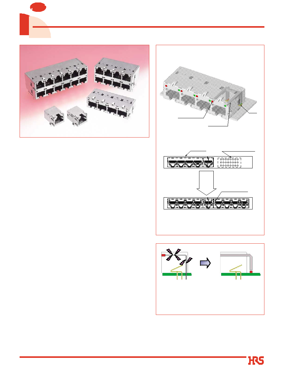
2. Built-in Optical Indicators
Optical indicators are integral part of the connectors
saving space on customer's board.
Compared with LED type indicators, they do not emit any
electrical noise.
3. EMI protection
Metal shield covers the outer surfaces of the connectors
assuring complete protection against electromagnetic
interference.
Built-in multiple shield and ground contacts assure
reliable connection with the mounting panel as well as
with the mating connector.
4. FCC Standards
Meets requirements of FCC Title 47, Part 68, Subpart F.
s
Applications
Telecom Hubs, Routers, Bridges and ATM Transmission
Equipment, Ethernet Switches and Networking Equipment,
Test and Measurement Equipment, Medical Diagnostic
Equipment.
Optical indicator
LED
Optical pipe
Housing
Optical indicator
Optical indicator area
Space
saving
One additional TM21 multi-port jack can be mounted
in the space previously occupied by LEDs.
Built-in Optical Indicators
Built-in LED type
(Possibility of
electromagnetic noise
emission and
interference.)
Built-in Optical pipe
type
(No electromagnetic
noise emission.)

2
s
Ordering information
s
Product Specifications
Ratings
Current rating
1A
Voltage rating
125 V AC
Operating temperature range-25
Á
to +80
Á
(Note)
s
Materials
Insulator
Contact
Optical pipe
Shield
PBT
Copper alloy
Poly carbonate
Copper alloy
Color: Black
Contact area: Gold plating
Termination area: Solder plating
Color: Clear
Tin plating
UL94V-0
-------
-------
-------
Part
Material
Finish
Remarks
Note :Includes temperature rise caused by current flow.
100 V DC
500 V AC / one minute
1500 V AC / one minute
100mA DC
200 cycles
Exposed to density 5% salt water for 48 hours
100 M ohms min
No flashover or insulation breakdown
No flashover or insulation breakdown
230 m ohms max.
Contact resistance: 250m ohms max.
Contact resistance: 250 m ohms max.
(Temperature: -55
Á/
+5
Á
to +35
Á/
+85
Á/
+5
Á
to +35
Á
Duration: 30
/
5
/
30
/
5 (Minutes)
5 cycles
0
1.Insulation resistance
0
2.Dielectric Withstanding Voltage
(between adjacent contacts)
0
3.Withstanding voltage
(between contact and shield)
0
4.Contact resistance
0
5.Vibration
0
6.Shock
0
7.Durability
(mating/unmating)
0
8.Temperature cycle
0
9.Humidity
10.Salt Spray
Item
Specification
Conditions
No electrical discontinuity of 5
ms
or more
Contact resistance: 250m ohms max.
Acceleration of 490 m/s
2
, 11 ms duration, sine half-wave
waveform, 3 cycles in each of the 3 axis
Contact resistance: 250 m ohms max.
Insulation resistance: 100 M ohms min.
Contact resistance: 250 m ohms max.
Insulation resistance: 1 M ohms min. (High humidity)
Insulation resistance: 10 M ohms min. (Dry state)
500 hours at temperature of 40
Á
and humidity of 90% to 95%
No electrical discontinuity of 5 ms or more
Contact resistance: 250m ohms max.
Frequency: 10 to 55 Hz, single amplitude of 0.75 mm,
2 hours / 3 axis
q
Series Name
TM21
w
Connector type
R : Jack
e
Jack type number
5 : PCB Right-angle through hole type
r
Jack performance level code A : CAT5 (Single row, multi-port)
B : CAT5 (Double row, multi port)
C : Supports CAT5e (Single port)
t
Jack opening code
8 : 8 contacts
32 : 8 contacts /4 ports
48 : 8 contact/6 ports
y
Number of inserted contacts 8 : 8 contact
32 : 8 contact inserted in 4 ports=32 contacts
48 : 8 contact inserted in 6 ports=48 contacts
u
Number of rows
Blank: Single row
D: Double row
i
Optical pipe
LP: With optical pipe inserted
Blank: Without optical pipe
TM21 R - 5 A - 32 32 D - LP
1
2
3
4
6
7
5
8
q
Jacks

3
s
Modular Jack Connectors Supporting CAT5e
q
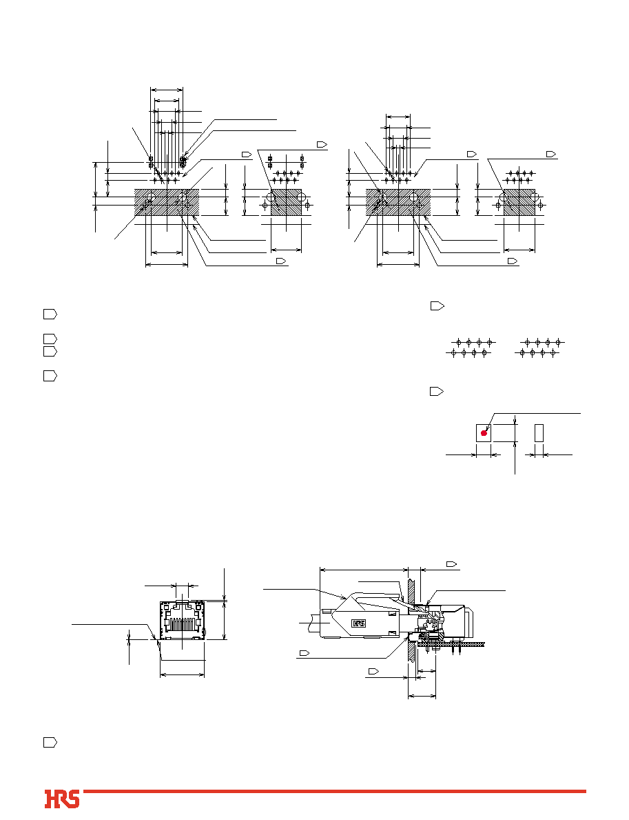
Single Port With Built-in Optical Pipe
TM21R-5C 1 PC
(5.5)
(2.8)
(5.5)
(5.5)
16
11.43
15.75
0.25
0.8
0.8
Contact No.1
Contact No.8
Contact No.2
Contact No.1
Contact No.7
Contact No.8
0.8
13.4
0.8
10.25
3.05
1
6.35
2.54
13.75
3
3.6
0.35
0.45
11.9
13.05
24
21
1.7
TM21R-5C 1 PC
(5.5)
(2.8)
(5.5)
(5.5)
16
11.43
15.75
0.25
0.8
0.8
Contact No.1
Contact No.8
Contact No.2
Contact No.1
Contact No.7
Contact No.8
0.8
13.4
0.8
10.25
3.05
1
6.35
2.54
13.75
3
3.6
0.35
0.45
11.9
13.05
24
21
1.7
CL No.
Part Number
222-2892-0
TM21R-5C-88-LP
q
Single Port Without Optical Pipe
CL No.
Part Number
222-2893-2
TM21R-5C-88
4
B
Recommended PCB mounting patterns
B
Panel Cutout
Other Series
8
7
6
5
4
3
2
1
TM21R Series
7
8
6
5
4
3
1
2
3.2MAX
2.7MAX
1.5MAX
LED light emitting center
PCB mounting pattern
Suggested LEDs
1
5
7
8
6
5
4
3
1
2
7
8
6
5
4
3
1
2
11.43
15.75
6.35
2.54
3.05
2-ÿ3.2
2-ÿ1.6
1.27
3.81
6.35
8.89
8-ÿ1
Contact No.
6.75
3MIN
No conductive traces
Printed board edge
Connector front edge
3MIN
6.75
11.43MIN
No ground traces
LED location area
11.43
15.75
6.35
2.54
3.05
2-ÿ1.6
1.27
3.81
6.35
8.89
8-ÿ1
Contact No.
6.75
3MIN
No conductive traces
Printed board edge
Connector front edge
11.9
13.05
LED light emission area
3MIN
6.75
11.43MIN
No ground traces
2-ÿ3.2
3
1
3
2
2
1
The contact arrangement differs between the contact area side and Printed board side.
(1,2,3,4,5,6,7,8 on the contact are side
/
2,1,3,4,5,6,8,7 on the printed board side)
Areas indicated should be free of conductive traces.
Area indicated should be free of ground traces.
Recommended board thickness: 1.6mm.
To assure that the indicator light pipes operates correctly the LED's must be
installed directly on the PCB, within recommended dimensions and with light
emitting center in upward direction.
Contact applicable manufacturer for LED specification.
1
2
3
4
5
q
With Built-in Optical Pipe
*
Recommendations for PCB Design
q
For Both Types, With and Without Built-in Optical Pipe
The shield contacts should connect with the panel cut-out on all sides.
1
*
Recommendations for Panel Design
q
Without Optical Pipe
10.25
Lock lever
6.75
2.8
0
-0.8
(33)
TM21P--88P
Connector front surface
4.5
+1
-2
14.1
0.6MIN
16.4
4.5MIN
0.15
PCB mounting surface
Panel side
TM21R--5C--88--LP
1
1
1
5
Manufacturer
Series Name
Citizen Electronics Co., Ltd.
Rohm Co., LTD
Rohm Co., LTD
CL-220
SML-010
SML-020
B
Recommended PCB mounting patterns
4
3MIN
LED location area
4-ÿ2
4-ÿ2
32-ÿ1
Contact No.
2 3 5 8
1 4 6 7
2-ÿ3.2
2.5
5.8
13.97
41.91
58.93
8.34
6MAX
12.7
8.34
LED
light emission area
53.81
Printed board edge
Connector front edge
15.525
1.27
3.81
6.35
8.89
No conductive traces
4
1
2
4
SML-010 Series
12.7
10.9
1.5
1.45
1.6
SML-020 Series
12.7
10.4
0.6
1
4.4
2.7
11.9
CL-220 Series
12.7
1.4
1.3
1.2
1
3
5
7
2
4
6
8
2
3
5
8
1
4
6
7
Suggested LEDs
1 PCB mounting pattern
LED Mount Area Dimensions
s
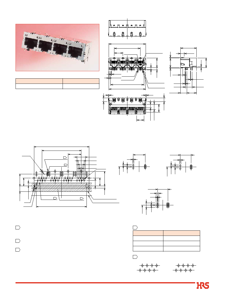
Modular Receptacles Supporting CAT5
1
15.3
15.4
2.5
8.34
15.525
5.8
0.45
8.34
0.25
0.35
12.7
11.9
1.4
3
1
1
59.18
13.97
41.91
15.4
58.93
53.81
Contact No.1
Contact No.8
Contact No.2
Contact No.1
Contact No.8
Contact No.7
3.6
0.75
1
25.9
1.7
10.25
(6)
(6)
(6)
(3.5)
CL No.
Part Number
222-2873-5
TM21R-5A-3232-LP
The contact arrangement differs between the contact area side and
Printed board side. (1,2,3,4,5,6,7,8 on the contact are side
/
2,1,3,4,5,6,8,7 on the printed board side)
Areas indicated should be free of conductive traces.
Recommended board thickness: 1.6mm.
To assure that the indicator light pipes operates correctly the LED's must
be installed directly on the PCB, within recommended dimensions and
with light emitting center in upward direction.
Contact applicable manufacturer for LED specification.
1
2
3
4
*
Recommendations for PCB Design
q
Single row/ multiple ports, with Built-in Optical Pipe

6
B
Recommended Panel Cutout
59.6
13.97
41.91
0.15
0.4MIN
PCB mounting surface
4.5MIN
15.8
Panels Side
Shield spring contact
1
Connector front surface
Lock lever
(34)
TM21P-- 88P
10.25
6 MAX
5
+1
- 2.5
3.5
0
-1
1
The shield contacts should connect with the panel cut-out on all sides.
1
*
Recommendations for Panel Design
7
1
3
5
7
2
4
6
8
8
6
4
2
7
5
3
1
Other Series
TM21R Series
2
3
5
8
1
4
6
7
7
6
4
1
8
5
3
2
PBT
1
2
1
3
4
5
6
8
7
2
1
3
4
5
6
8
7
22.125
0.45
Lower row connectors
contacts
Upper row connectors contacts
A
B
13.97
C
D
0.25
28
3
3.6
1
1
7.7
5.8
8.34
12.4
14.94
19.3
27.9
1
0.75
10.25
1.4
2.5
14.94
0.35
32.5
28
1.7
Contact No.8
Contact No.1
Lower row
Upper row
Contact No.1
Contact No.8
(6)
(3.5)
(6)
(6)
11.9
B
Recommended PCB mounting pattern
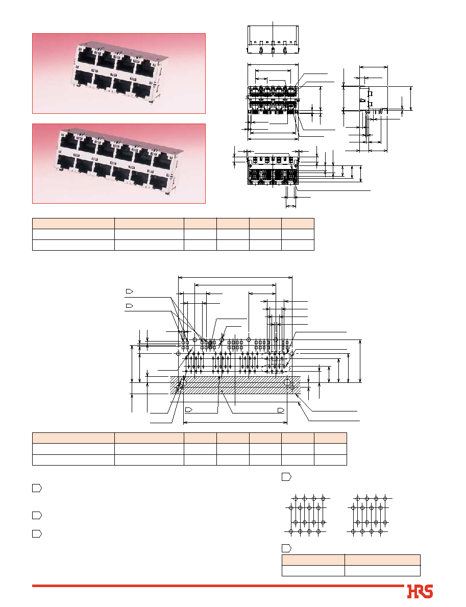
Part Number
CL No.
TM21R-5B-3232D-LP
TM21R-5B-4848D-LP
A
B
C
D
59.18
87.12
41.91
69.85
53.81
81.75
58.93
86.87
222-2879-1
222-2885-4
Part Number
CL No.
TM21R-5B-3232D-LP
TM21R-5B-4848D-LP
A
B
C
D
E
58.93
86.87
41.91
69.85
53.81
81.75
64
96
4
6
222-2879-1
222-2885-4
TM21R-5B-3232D-LP
TM21R-5B-4848D-LP
2 3 5 8
1 4 6 7
7 6 4 1
8 5 3 2
No conductive traces
Printed board edge
Connector front edge
C
4- ÿ2
2- ÿ3.2
3
M
I
N
14.94
D- ÿ1
11.9
7.7
2.5
5.8
8.34
12.4
14.94
B
13.97
1.27
3.81
6.35
8.89
Contact No.
Upper row contact hole
Lower row contact hole
LED light
emission area
22.125
A
Upper row LED
mount position
Lower row LED
mount position
E- ÿ2
1.2
1.4
1.3
2
1
4
4
MAX
19.3
6
The contact arrangement differs between the contact area side and
Printed board side. (1,2,3,4,5,6,7,8 on the contact are side
/
2,1,3,4,5,6,8,7 on the printed board side)
Areas indicated should be free of conductive traces.
Recommended board thickness: 1.6mm.
To assure that the indicator light pipes operates correctly the LED's
must be installed directly on the PCB, within recommended dimensions
and with light emitting center in upward direction.
Contact applicable manufacturer for LED specification.
1
2
3
4
*
Recommendations for PCB Design
q
Double row / multiple port, with Built-in Optical Pipe
Manufacturer
Series Name
Citizen Electronics Co., Ltd.
CL-220
4 Suggested LEDs
1 PCB mounting pattern

8
B
Panes Cutout
1
28.4
0.4 MIN
B
A
13.97
4.5MIN
PCB mounting surface
0.15
Panel Side
Shield spring
contact spring
1
1
1
(34)
TM21R -- 5B -- * * * * D -- LP
TM21P -- 88P
6 MAX
Connector front surface
5
+1
-2.5
3.5
0
-1
10.25
Lock lever
The shield contacts should connect with the panel cut-out on all sides.
1
*
Recommendations for Panel Design
Part Number
CL No.
TM21R-5B-3232D-LP
TM21R-5B-4848D-LP
A
B
41.91
69.85
59.6
0
87.54
222-2879-1
222-2885-4
9
B
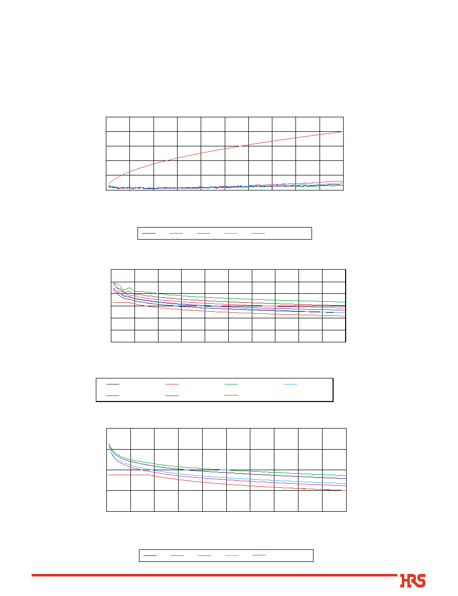
Technical Documentation CAT5e Transmission Characteristics Data
Representative values of the various transmission characteristics data for fully mated receptacle (TM21R-5C-88-LP)
and plug (TM21P-88P).
All plugs in the TM21R-5C Series that were manufactured based on the De-embedded method of the TIA/EIA-568-B.2
standard and meet performance requirements of CAT5e single transmission.
Note:These data are for the listed connector combination. Inquire with your Hirose Electric account representative about other
combinations.
q
Signal Attenuation
0
0.1
0.2
0.3
0.4
0.5
0 10203040506070809010
0
Frequency(MHz)
Attenuation(dB)
1,2
3,6
4,5
7,8
CAT5e Spec
0
20
40
60
80
100
120
0 10203040506070809010
0
Frequency(MHz)
NEXT(dB)
1,2-3,6
1,2-4,5
1,2-7,8
3,6-4,5
3,6-7,8
4,5-7,8
CAT5e Spec
q
Near-End Crosstalk (NEXT) Data
0
20
40
60
80
0 10203040506070809010
0
Frequency(MHz)
Return Loss(dB)
1,2
3,6
4,5
7,8
CAT5e Spec
q
Return Loss

10
0
0.2
0.4
0.6
0.8
1
1.2
1.4
0 10203040506070809010
0
Frequency(MHz)
Delay Skew(ns)
Measurement Value
CAT5e Spec
q
Far-End Crosstalk (FEXT)
0
20
40
60
80
100
120
0 10203040506070809010
0
Frequency(MHz)
FEXT(dB)
1,2-3,6
1,2-4,5
1,2-7,8
3,6-1,2
3,6-4,5
3,6-7,8
4,5-1,2
4,5-3,6
4,5-7,8
7,8-1,2
7,8-3,6
7,8-4,5
CAT5e Spec
q
Propagation Delay
0
0.5
1
1.5
2
2.5
3
0 10203040506070809010
0
Frequency(MHz)
Delay(ns)
1,2
3,6
4,5
7,8
CAT5e Spec
q
Propagation Delay (Delay Skew)

11
B
Reference Documentation
q
CAT6 Certification Received
Only the high quality plugs in the TM21R-5C Series (based on the De-embedded method of the TIA/EIA-568-B.2
standard) clear CAT6 single transmission performance. A certificate was issued by the GHMT, independent
European testing company.
Return Loss
NEXT
Certificate of Acceptance

12
The contents of this catalog are current as of date of publication. Contents are subject to change without notice for the purpose of product improvements.
USA:
HIROSE ELECTRIC U.S.A., INC.
2688 Westhills Court, Simi Valley, CA 93065-6235
Phone : 1 805 522 7958
Fax : 1 805 522 3217
http://www.hirose.com
UNITED KINGDOM:
HIROSE ELECTRIC UK LTD.
Crownhill Business Centre 22 Vincent Avenue
Crownhill, Milton Keynes MK8 OAB
Phone : 44 1908 305400
Fax : 44 1908 305401
http://www.hirose.co.uk
HONG KONG:
HIROSE ELECTRIC CO., LTD.
Unit 506, Energy Plaza. 92 Granville Road, Tsim Sha
Tsui East, Kowloon
Phone : 852 2803 5338
Fax : 852 2591 6560
EUROPE BRANCH:
HIROSE ELECTRIC CO., LTD.
First Class Building 4F, Beechavenue 46.1119PV
Schiphol-Rijk, The Netherlands
Phone : 31 20 6557 460
Fax : 31 20 6557 469
http://hiroseeurope.com
KOREA:
HIROSE KOREA CO., LTD.
(#2NA311,Shihwa Industrial Complex),
1261-10, Jeoungwhang-Dong, Shihung-City, Kyunggi-Do
Phone : 82 31 496 7000,7124
Fax : 82 31 496 7101
http://www.hirose.co.kr
TAIWAN:
HIROSE ELECTRIC CO., LTD.
No.28 Lane 247 Sec. 2 Yen Ping N,Rd.Taipei
Phone : 886 2 2557 7351,7352
Fax : 886 2 2552 9851
GERMANY:
HIROSE ELECTRIC GmbH
Zeppelinstrasse 42 D-73760 Ostfildern Kemnat
Phone : 49 711 4560021
Fax : 49 711 4560729
http://www.hirose.de
CHINA:
HIROSE ELECTRIC CO., LTD.
10F,No.06, Shanghai Times Square office Tower,
93. Huai Hai Zhong Road, Luwan Shanghai
Phone : 86 21 6391 0011
Fax : 86 21 6391 0101
SINGAPORE:
HIROSE ELECTRIC CO., LTD.
10 Anson Road
#34-13 International Plaza 079903
Phone : 65 6324 6113
Fax : 65 6324 6123
5-23,OSAKI 5-CHOME,SHINAGAWA-KU,TOKYO 141-8587,JAPAN
PHONE: 81-3-3491-9741, FAX: 81-3-3493-2933
HIROSE ELECTRIC CO., LTD.
C
re
at
iv
e
Lin
ks to World Ele
ctr
on
ic
s
Æ