3SK322
Silicon N-Channel Dual Gate MOS FET
ADE-208-712A (Z)
2nd. Edition
Dec. 1998
Application
UHF / VHF RF amplifier
Features
∑
Low noise figure.
NF = 1.0 dB typ. at f = 200 MHz
∑
Capable of low voltage operation
∑
Provide mini mold packages; MPAK-4R(SOT-143 var.)
Outline

3SK322
2
Absolute Maximum Ratings (Ta = 25∞C)
Item
Symbol
Ratings
Unit
Drain to source voltage
V
DS
12
V
Gate 1 to source voltage
V
G1S
±8
V
Gate 2 to source voltage
V
G2S
±8
V
Drain current
I
D
25
mA
Channel power dissipation
Pch
150
mW
Channel temperature
Tch
150
∞C
Storage temperature
Tstg
≠55 to +150
∞C
Attention: This device is very sensitive to electro static discharge.
It is recommended to adopt appropriate cautions when handling this transistor.

3SK322
3
Electrical Characteristics (Ta = 25∞C)
Item
Symbol
Min
Typ
Max
Unit
Test conditions
Drain to source breakdown voltage V
(BR)DSX
12
--
--
V
I
D
= 200 µA , V
G1S
= ≠3 V,
V
G2S
= ≠3 V
Gate 1 to source breakdown
voltage
V
(BR)G1SS
±8
--
--
V
I
G1
= ±10 µA, V
G2S
= V
DS
= 0
Gate 2 to source breakdown
voltage
V
(BR) G2SS
±8
--
--
V
I
G2
= ±10 µA, V
G1S
= V
DS
= 0
Gate 1 cutoff current
I
G1SS
--
--
±100
nA
V
G1S
= ±6 V, V
G2S
= V
DS
= 0
Gate 2 cutoff current
I
G2SS
--
--
±100
nA
V
G2S
= ±6 V, V
G1S
= V
DS
= 0
Drain current
I
DS(on)
0.5
--
10
mA
V
DS
= 6 V, V
G1S
= 0.75V,
V
G2S
= 3 V
Gate 1 to source cutoff voltage
V
G1S(off)
0
--
+1.0
V
V
DS
= 10 V, V
G2S
= 3V,
I
D
= 100 µA
Gate 2 to source cutoff voltage
V
G2S(off)
0
--
+1.0
V
V
DS
= 10 V, V
G1S
= 3V,
I
D
= 100 µA
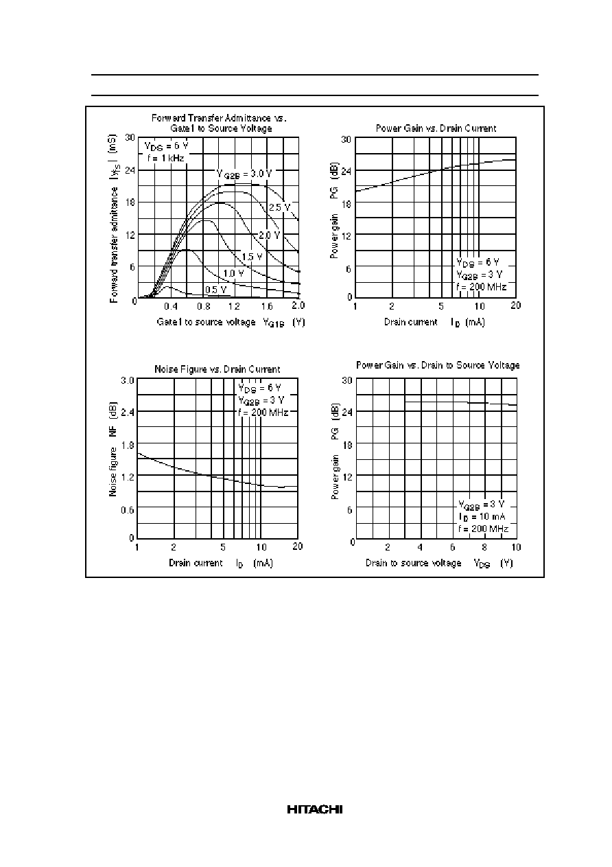
Forward transfer admittance
|y
fs
|
16
20
--
mS
V
DS
= 6 V, V
G2S
= 3V,
I
D
= 10 mA, f = 1 kHz
Input capacitance
Ciss
2.4
2.9
3.4
pF
V
DS
= 6 V, V
G2S
= 3V,
I
D
= 10 mA, f = 1 MHz
Output capacitance
Coss
0.8
1.0
1.4
pF
Reverse transfer capacitance
Crss
--
0.023
0.04
pF
Power gain
PG
22
25
--
dB
V
DS
= 6 V, V
G2S
= 3V,
I
D
= 10 mA, f = 200 MHz
Noise figure
NF
--
1.0
1.8
dB
Power gain
PG
12
15
--
dB
V
DS
= 6 V, V
G2S
= 3V,
I
D
= 10 mA, f = 900 MHz
Noise figure
NF
--
3.2
4.5
dB
Noise figure
NF
--
2.8
3.5
dB
V
DS
= 6 V, V
G2S
= 3V,
I
D
= 10 mA, f = 60 MHz
Note:
Marking is "ZW≠"

3SK322
12
Cautions
1. Hitachi neither warrants nor grants licenses of any rights of Hitachi's or any third party's patent,
copyright, trademark, or other intellectual property rights for information contained in this document.
Hitachi bears no responsibility for problems that may arise with third party's rights, including
intellectual property rights, in connection with use of the information contained in this document.
2. Products and product specifications may be subject to change without notice. Confirm that you have
received the latest product standards or specifications before final design, purchase or use.
3. Hitachi makes every attempt to ensure that its products are of high quality and reliability. However,
contact Hitachi's sales office before using the product in an application that demands especially high
quality and reliability or where its failure or malfunction may directly threaten human life or cause risk
of bodily injury, such as aerospace, aeronautics, nuclear power, combustion control, transportation,
traffic, safety equipment or medical equipment for life support.
4. Design your application so that the product is used within the ranges guaranteed by Hitachi particularly
for maximum rating, operating supply voltage range, heat radiation characteristics, installation
conditions and other characteristics. Hitachi bears no responsibility for failure or damage when used
beyond the guaranteed ranges. Even within the guaranteed ranges, consider normally foreseeable
failure rates or failure modes in semiconductor devices and employ systemic measures such as fail-
safes, so that the equipment incorporating Hitachi product does not cause bodily injury, fire or other
consequential damage due to operation of the Hitachi product.
5. This product is not designed to be radiation resistant.
6. No one is permitted to reproduce or duplicate, in any form, the whole or part of this document without
written approval from Hitachi.
7. Contact Hitachi's sales office for any questions regarding this document or Hitachi semiconductor
products.