HD74HC173
4-bit D-type Register (with 3-state Outputs)
Description
The four D type Flip-Flops operate synchronously from a common clock. The 3-state outputs allow the
device to be used in bus organized systems. The outputs are placed in the 3-stage mode when either of the
output disable pins are in the logic high level.
The input disable allows the flip-flops to remain in their present states without having to disrupt the clock.
If either of the 2 input disables are taken to a logic high level, the Q outputs are fed back to the inputs,
forcing the flip-flops to remain in the same state. Clearing is enabled by taking the clear input to a logic
high level. The data outputs change state on the positive going edge of the clock.
Features
∑
High Speed Operation: t
pd
(Clock to Q) = 14 ns typ (C
L
= 50 pF)
∑
High Output Current: Fanout of 10 LSTTL Loads
∑
Wide Operating Voltage: V
CC
= 2 to 6 V
∑
Low Input Current: 1 µA max
∑
Low Quiescent Supply Current: I
CC
(static) = 4 µA max (Ta = 25∞C)
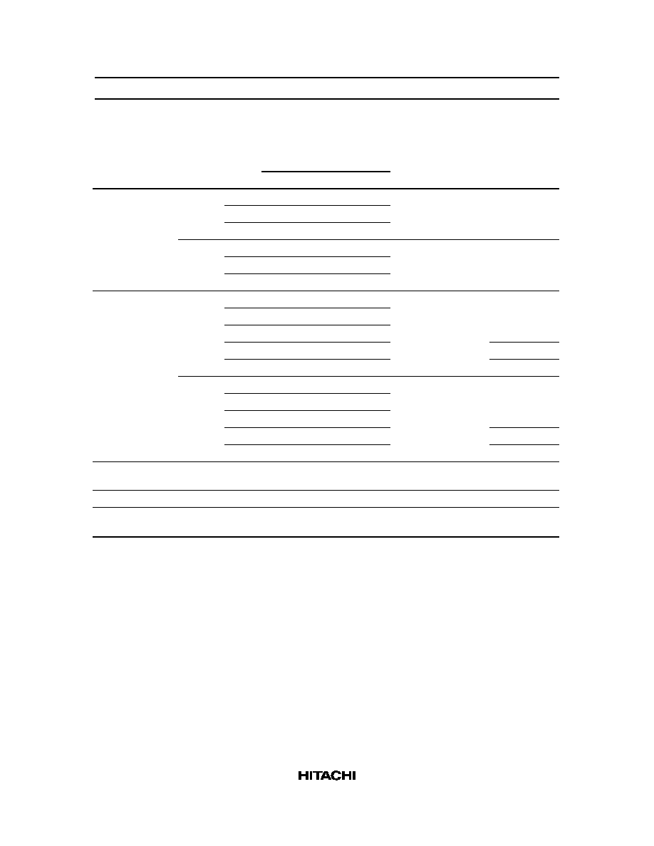
Function Table
Inputs
Data Enable
Clear
Clock
G
1
G
2
Data D
Output Q
H
X
X
X
X
L
L
L
X
X
X
Q
0
L
H
X
X
Q
0
L
X
H
X
Q
0
L
L
L
L
L
L
L
L
H
H
Note:
When either M or N (or both) is (are) high the output is disabled to the high-impedance state;
however sequential operation of the flip-flops is not affected.

HD74HC173
2
Pin Arrangement
1
2
3
4
5
6
7
8
M
N
1Q
2Q
3Q
4Q
Clock
GND
V
CC
Clear
1D
2D
3D
4D
G
2
G
1
16
15
14
13
12
11
10
9
Output
Control
Data
Input
Data
Enable
Input
Output
Control
Output
Data
Enable
Clear
1Q
2Q
3Q
4Q
1D
2D
3D
4D
CK
(Top view)
Absolute Maximum Ratings
Item
Symbol
Rating
Unit
Supply voltage range
V
CC
≠0.5 to +7.0
V
Input voltage
V
IN
≠0.5 to V
CC
+ 0.5
V
Output voltage
V
OUT
≠0.5 to V
CC
+ 0.5
V
DC current drain per pin
I
OUT
±
35
mA
DC current drain per VCC, GND
I
CC
, I
GND
±
75
mA
DC input diode current
I
IK
±
20
mA
DC output diode current
I
OK
±
20
mA
Power dissipation per package
P
T
500
mW
Storage temperature
Tstg
≠65 to +150
∞
C