 | ÐлекÑÑоннÑй компоненÑ: BRC114ECM | СкаÑаÑÑ:  PDF PDF  ZIP ZIP |
Äîêóìåíòàöèÿ è îïèñàíèÿ www.docs.chipfind.ru
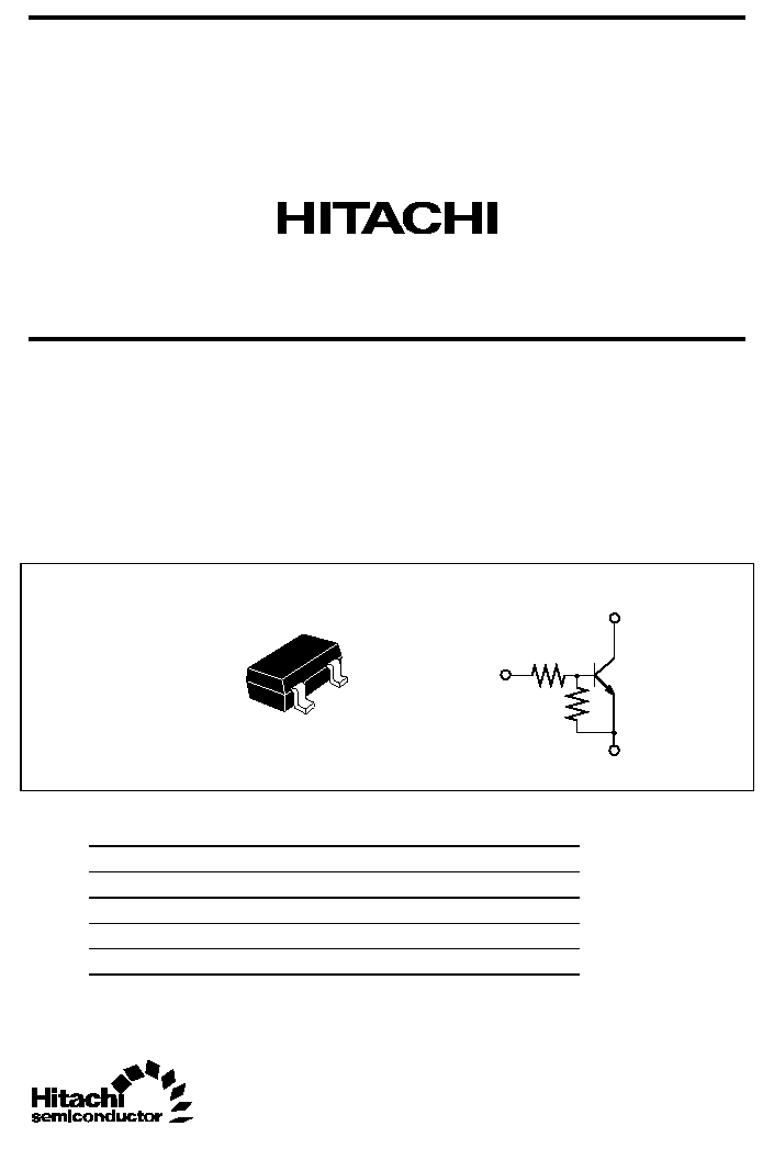
BRC144ECM Series
NPN Built-in Resistor Transistor CMPAK Series
Inverter, Driver, Switching
ADE-208-1445B (Z)
Rev.2
Sep. 2001
Features
· Builtin Resistor Type
· Simplifies Circuit Design
· Reduces Board Space
· Complementary pair with BRA144ECM series
Outline
1
2
3
1. Ground (Emitter)
2. Input (Base)
3. Output (Collector)
3
2
1
R
1
R
2
CMPAK
Note:
Marking is shown in below.
Device
Marking
R1 (k
)
R2 (k
)
BRC144ECM
BG
47
47
BRC124ECM
DG
22
22
BRC114ECM
FG
10
10
BRC143ECM
HG
4.7
4.7
BRC123ECM
KG
2.2
2.2

BRC144ECM Series
Rev.2, Sep. 2001, page 2 of 12
Absolute Maximum Ratings
(Ta = 25
°C)
Item
Symbol
Ratings
Unit
Supply voltage
V
CC
50
V
BRC144ECM
-10 to +50
BRC124ECM
-10 to +45
BRC114ECM
-10 to +30
BRC143ECM
-10 to +20
Input voltage
BRC123ECM
V
I
-10 to +15
V
Output current
I
O
100
mA
Total power dissipation
P
T
*
150
mW
Junction temperature
Tj
150
°C
Storage temperature
Tstg
-55 to +150
°C
*Value on the glass epoxy board. (10 mm
× 10 mm × 0.7 mm)

BRC144ECM Series
Rev.2, Sep. 2001, page 3 of 12
Electrical Characteristics
(Ta = 25
°C)
Item
Symbol
Min
Typ
Max
Unit
Test conditions
BRC144ECM
1.5
4.5
BRC124ECM
1.3
3.0
BRC114ECM
1.2
2.4
BRC143ECM
1.1
2.0
Input on voltage
BRC123ECM
V
I(on)
1.1
1.8
V
V
CC
= 0.3 V, I
O
= 5 mA
BRC144ECM
1.0
1.5
BRC124ECM
1.0
1.5
BRC114ECM
1.0
1.5
BRC143ECM
1.0
1.5
Input off voltage
BRC123ECM
V
I(off)
1.0
1.5
V
V
CC
= 5 V, I
O
= 100
µA
Output saturation voltage
V
O(on)
0.3
V
I
O
= 10 mA, I
I
= 0.5 mA
Output cutoff current
I
O(off)
0.5
µA
V
CC
= 50 V, I
I
= 0
BRC144ECM
70
BRC124ECM
56
BRC114ECM
30
V
CC
= 5 V, I
O
= 5 mA
BRC143ECM
20
V
CC
= 5 V, I
O
= 10 mA
DC current
transfer ratio
BRC123ECM
Gi
20
V
CC
= 5 V, I
O
= 20 mA
BRC144ECM
33
47
61
BRC124ECM
15
22
28
BRC114ECM
7
10
13
BRC143ECM
3.3
4.7
6.1
Input resistance
BRC123ECM
R
1
1.5
2.2
2.8
k
Resistance ratio
R
1
/R
2
0.8
1.0
1.2
BRC144ECM Series
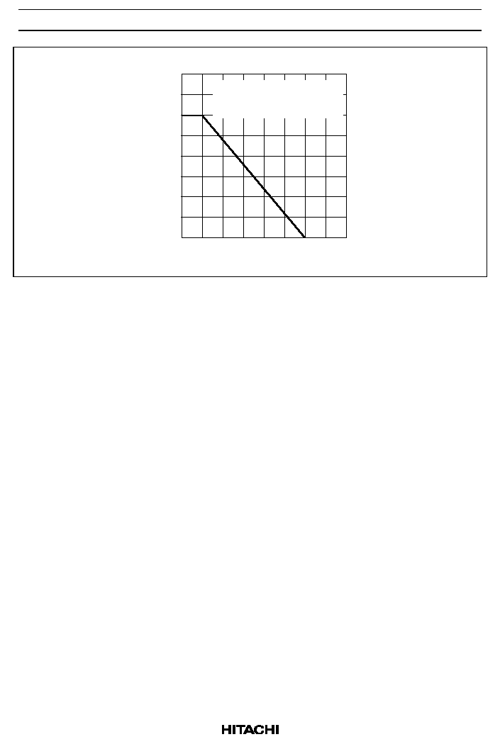
Rev.2, Sep. 2001, page 4 of 12
200
150
100
50
0
50
100
150
200
Ambient Temperature Ta (
°C)
T
otal P
o
w
er Dissipation P
T
* (mW)
Total Power Dissipation Curve
*Value on
the grass epoxy board.
(10 mm
× 10 mm × 0.7 mm)
BRC144ECM Series
Rev.2, Sep. 2001, page 5 of 12
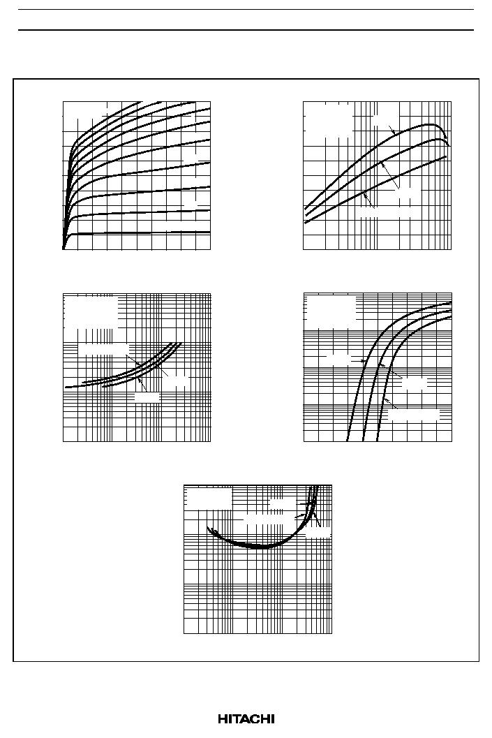
Main Characteristics (BRC144ECM)
100
80
60
40
20
0
1
2
3
4
5
Supply Voltage V
CC
(V)
Output Current I
O
(mA)
0.5
1.0
1.5
2.0
2.5
0
10
1.0
0.1
0.01
0.001
Output Current I
O
(mA)
Input Voltage V
I
(V)
1.0
0.1
0.01
0.01
Output On
V
oltage
V
O(on)
(V)
1.0
10
100
0.1
Output Current I
O
(mA)
100
10
1.0
0.1
Input
V
oltage
V
I
(V)
0.1
1.0
10
100
Output Current I
O
(mA)
200
100
0
1
10
100
Output Current I
O
(mA)
Output Current vs. Supply Voltage
DC Current Gain Gi
Input Voltage vs. Output Current
Output On Voltage vs. Output Current
DC Current Gain vs. Output Current
Output Current vs. Input Voltage
R
L
= 0
Pulse test
I
I
= 0.1 mA
1.0
0.2
0.3
0.4
0.5
0.6
0.7
0.8
0.9
V
CC
= 5 V
R
L
= 0
Pulse test
I
O
/ I
I
= 20
Pulse test
V
CC
= 5 V
R
L
= 0
Pulse test
V
CC
= 0.3 V
R
L
= 0
Pulse test
Ta = 25 °C
25 °C
75 °C
Ta = 25 °C
25 °C
75 °C
Ta = 25 °C
25 °C
75 °C
Ta = 25 °C
25 °C
75 °C