
HA12215F
Audio Signal Processor for Cassette Deck
(Dolby B-type NR with Recording System)
ADE-207-253D (Z)
Target Specification
5th Edition
Oct. 1999
Description
HA12215F is silicon monolithic bipolar IC providing Dolby noise reduction system*
1
, music sensor
system, REC equalizer system and each electronic control switch in one chip.
Note: 1. Dolby is a trademark of Dolby Laboratories Licensing Corporation.
A license from Dolby Laboratories Licensing Corporation is required for the use of this IC.
Functions
∑
Dolby B-NR
◊
2 channel
∑
REC equalizer
◊
2 channel
∑
Music sensor
◊
1 channel
∑
Pass amp.
◊
2 channel
∑
Each electronic control switch to change REC equalizer, bias, etc.
Features
∑
REC equalizer is very small number of external parts and have 6 types of frequency characteristics
built-in.
∑
2 types of input for PB, 1 type of input for REC.
∑
70
µ
- PB equalizer changing system built-in.
∑
Dolby NR with dubbing double cassette decks.
Unprocessed signal output available from recording out terminals during PB mode.
∑
Provide stable music sensor system, available to design music sensing time and level.
∑
Controllable from direct micro-computer output.
∑
Bias oscillator control switch built-in.
∑
NR ON / OFF and REC / PB fully electronic control switching built-in.
∑
Normal-speed / high-speed, Normal / Crom / Metal and PB equalizer fully electronic control switching
built-in.
∑
Available to reduce substrate-area because of high integration and small external parts.

HA12215F
Rev.5, Oct. 1999, page 2 of 69
Ordering Information
Operating Voltage
Product
V
CC
(V)
V
EE
(V)
Note
HA12215F
+6.0 to +7.5
≠7.5 to ≠6.0
|
V
CC
+ V
EE
|
< 1.0 V
Standard Level
Product
Package
PB-OUT Level
REC-OUT Level
Dolby Level
HA12215F
FP-56
580 mVrms
300 mVrms
300 mVrms
Function
Product
Dolby B-NR
REC-EQ
Music
Sensor
Pass Amp.
REC / PB
Selection
ALC
HA12215F
Note:
Depending on the employed REC / PB head and test tape characteristics, there is a rare case that
the REC-EQ characteristics of this LSI can not be matched to the required characteristics because of
built-in resistors which determined the REC-EQ parameters in this case, please inquire the
responsible agent because the adjustment built-in resistor is necessary.
HA12215F
Rev.5, Oct. 1999, page 3 of 69
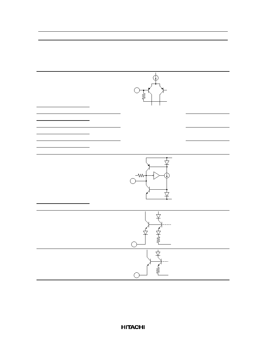
Pin Description, Equivalent Circuit (V
CC
= ±7 V, A system of split supply voltage,
Ta = 25∞C, No Signal, The value in the show typical value.)
Pin No.
Terminal Name
Note
Equivalent Circuit
Pin Description
51
AIN (R)
V = GND
GND
V
100k
PB A Deck input
48
AIN (L)
53
BIN (R)
V = GND
PB B Deck input
46
BIN (L)
56
RIN (R)
V = GND
REC input
43
RIN (L)
5
EQIN (R)
V = GND
REC equalizer input
38
EQIN (L)
1
DET (R)
V = V
EE
+2.7V
V
CC
V
EE
V
Time constant pin for
Dolby-NR
42
DET (L)
2
BIAS1
V = V
EE
+0.6V
V
EE
V
Dolby bias current
input
41
BIAS2
V = V
EE
+1.3V
V
EE
V
REC equalizer bias
current input

HA12215F
Rev.5, Oct. 1999, page 4 of 69
Pin Description, Equivalent Circuit (V
CC
= ±7 V, A system of split supply voltage,
Ta = 25∞C, No Signal, The value in the show typical value.) (cont)
Pin No.
Terminal Name
Note
Equivalent Circuit
Pin Description
3
PBOUT (R)
V = GND
V
CC
V
EE
V
PB output
40
PBOUT (L)
4
RECOUT (R)
V = GND
REC output
39
RECOUT (L)
7
EQOUT (R)
V = GND
REC equalizer output
36
EQOUT (L)
28
MAOUT
V = GND
MS Amp. output *
1
8
ROUT (R)
V = GND
Input Amp. output
35
ROUT (L)
52
ABO (R)
R1 = 15 k
R2 = 12 k
V
CC
V
EE
R2
R1
V
Time constant pin for
PB equalizer (70
µ
)
47
ABO (L)
6
BOOST (R)
R1 = 4.8 k
R2 = 4.8 k
Time constant pin for
low boost
37
BOOST (L)
31
BIAS (M)
V = V
CC
≠ 0.7V
V
CC
V
REC bias current
output
32
BIAS (C)
33
BIAS (N)
Note:
1. MS: Music Sensor

HA12215F
Rev.5, Oct. 1999, page 5 of 69
Pin Description, Equivalent Circuit (V
CC
= ±7 V, A system of split supply voltage,
Ta = 25∞C, No Signal, The value in the show typical value.) (cont)
Pin No.
Terminal Name
Note
Equivalent Circuit
Pin Description
21
V
CC
V = V
CC
Power supply
49
GND
V = 0V
GND pin
50
V
EE
V = V
EE
Negative power
supply
45, 54
NC
No connection
No connection
15
ALC
ON
/OFF
I = 50
µ
A
22 k
GND
V
I
100 k
Mode control input
16
PB
A
/B
17
A
120
/70
18
NORM
/HIGH
19
B
NORM
/CROM/
METAL
20
BIAS ON/
OFF
22
RM
ON
/OFF
23
NR ON/
OFF
25
LM ON/
OFF
24
REC
/PB/PASS
2.5 V
100 k
100 k
-
+
V
22 k
Mode control input
26
MSOUT
I = 0
µ
A
V
I
MSGND
V
CC
V
EE
MS output (to MPU) *
1
Note:
1. MS: Music Sensor