HD74HC160/HD74HC161/
HD74HC162/HD74HC163
Synchronous Decade Counter (Direct Clear)
Synchronous 4-bit Binary Counter (Direct Clear)
Synchronous Decade Counter (Synchronous Clear)
Synchronous 4-bit Binary Counter (Synchronous Clear)
Description
The HD74HC160 and the HD74HC162 are 4 bit decade counters, and the HD74HC161 and the
HD74HC163 are 4 bit binary counters All flip-flops are clocked simultaneously on the low to high to
transition (positive edge) of the clock input waveform.
These counters may be preset using the load input. Presetting of all four flip-flops is synchronous to thte
rising edge of clock. When load is held low counting is disabled and the data on the A, B, C, and D inputs
is loaded into the counter on the rising edge of clock. If the load input is taken high before the positive
edge of clock the count operation will be unaffected.
All of these counters may be cleared by utilizing the clear input. The clear function on the HD74HC162
and HD74HC163 counters are synchronous to the clock. That is, the counters are cleared on the positive
edge of clock while the clear input is held low.
The HD74HC160 and HD74HC161 counters are cleared asynchronously. When the clear is taken low the
counter is cleared immediately regardless of the clock.
Two active high enable inputs Enable P and Enable T and a ripple carry output are provided to enable easy
cascading of counters. Both enable inputs must be high to count. The Enable T input also enables the
Ripple Carry output. When enabled, the Ripple Carry outputs a positive pulse when the counter overflows.
This pulse is approximately equal in duration to the high level portion of the Q
A
outputs. The Ripple Carry
output is fed to successive cascaded stages to facilitate easy implementation of N-bit counters.
Features
∑
High Speed Operation: t
pd
(Clock to Q) = 18 ns typ (C
L
= 50 pF)
∑
High Output Current: Fanout of 10 LSTTL Loads
∑
Wide Operating Voltage: V
CC
= 2 to 6 V
∑
Low Input Current: 1 µA max
HD74HC160/HD74HC161/HD74HC162/HD74HC163
2
∑
Low Quiescent Supply Current: I
CC
(static) = 4 µA max (Ta = 25∞C)
Function Table
Inputs
Outputs
Clock
Clear
*
1
Load
Enable P
Enable T
Q
n
L
X
X
X
Reset-clear
H
L
X
X
Load input data
H
H
H
H
Count
H
H
L
X
No count
H
H
X
L
No count
Note:
1. 162 and 163 Only-160 and 161 are Asynchronous Clear Devices
Decade Counter
Binary Counter
Asynchronous clear
HD74HC160P
HD74HC161P
Synchronous clear
HD74HC162P
HD74HC163P
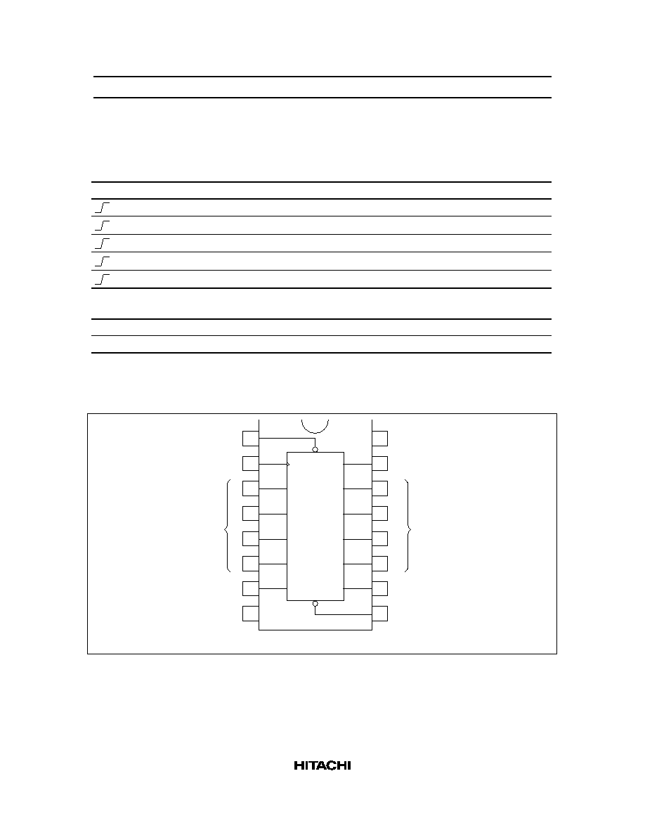
Pin Arrangement
1
2
3
4
5
6
7
8
Clear
Clock
A
B
C
D
Enable P
GND
V
CC
Q
A
Q
B
Q
C
Q
D
Enable T
Load
16
15
14
13
12
11
10
9
(Top view)
CK
P
A
C
D
B
Ripple
Carry
Ripple
Carry Output
Outputs
Data
Inputs
Q
A
Q
B
Q
D
T
Q
C
CLR
Load

HD74HC160/HD74HC161/HD74HC162/HD74HC163
4
AC Characteristics (C
L
= 50 pF, Input t
r
= t
f
= 6 ns)
Ta = 25
∞
C
Ta = ≠40 to
+85
∞
C
Item
Symbol
V
CC
(V) Min Typ Max Min
Max
Unit Test Conditions
Maximum clock
f
max
2.0
--
--
5
--
4
MHz
frequency
4.5
--
--
25
--
20
6.0
--
--
29
--
23
Propagation delay t
PLH
2.0
--
--
160 --
200
ns
Clock to Q
time
t
PHL
4.5
--
18
32
--
40
6.0
--
--
27
--
34
2.0
--
--
225 --
280
ns
Clear
to Q
4.5
--
23
45
--
56
(HC160, HC161 only)
6.0
--
--
38
--
48
2.0
--
--
150 --
190
ns
Enable T to Ripple Carry output
4.5
--
15
30
--
38
6.0
--
--
26
--
33
2.0
--
--
200 --
250
ns
Clock to Ripple carry output
4.5
--
16
40
--
50
6.0
--
--
34
--
43
Setup time
t
su
2.0
125 --
--
156
--
ns
Data to Clock
4.5
25
9
--
31
--
6.0
21
--
--
26
--
2.0
125 --
--
156
--
Load
to Clock
4.5
25
15
--
31
--
6.0
21
--
--
26
--
2.0
125 --
--
156
--
Clear
to Clock
4.5
25
--
--
31
--
(HC162, HC163 only)
6.0
21
--
--
26
--
Hold time
t
h
2.0
0
--
--
0
--
ns
4.5
0
≠7
--
0
--
6.0
0
--
--
0
--
Removal time
t
rem
2.0
100 --
--
125
--
ns
4.5
20
7
--
25
--
6.0
17
--
--
21
--