HD74HC190/HD74HC191
Synchronous Up/Down Decade Counter (Single Clock Line)
Synchronous Up/Donw 4-bit Binary Counter (Single Clock Line)
Description
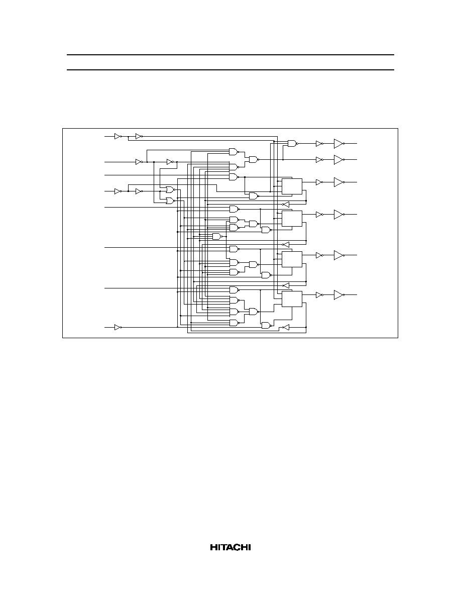
The HD74HC190 and HD74HC191 are synchronous, reverside up/down counters. The HD74HC190 is a
4-bit decade counter and the HD74HC191 is a 4-bit binary counter. Synchronous counting operation is
provided by having all flip-flops clocked simultaneously so that the outputs change coincident with each
other when so instructed by the steering logic. This mode of operation eliminates the output counting
spikes normally associated with asynchronous (ripple clock) counters.
The outputs of the four flip-flops are triggered on a low-to-high-level transition of the clock input if the
Enable G input is low. A high at Enable G inhibits counting. The direction of the count is determined by
the level of the Down/ Up (D/
U) input. When D/U is low, the counter counts up and when D/U is high, it
counts down.
These counters feature a fully independent clock circuit. Changes at the control inputs (D/
U) that will
modify the operating mode have no effect on the contents of the counter until clocking occurs. The
function of the counter will be dictated solely by the condition meeting the stable setup and hold times.
These counters are fully programmable; that is, the outputs may each be preset to either level by placing a
low on the load input and entering the desired data at the data inputs. The output will change to agree with
the data inputs independently of the level of the clock input. This feature allows the counters to be used as
modulo-N dividers by simply modifying the count length with the preset inputs.
Two outputs have been made available to perform the cascading function. Ripple clock and
maximum/minimum count. The latter output produces a high-level output pulse with a duration
approximately qual to one complete cycle of the clock while the count is zero (all outputs low) counting
down or maximum (9 or 15) counting up. The ripple clock output produces a low-level output pulse under
those same conditions but only while the clock input is low. The counters can be easily cascaded by
feeding the ripple clock output to the enable input of the succeeding counter if parallel clocking is used, or
to the clock input if paralle enabling is used. The maximum/minimum count output can be used to
accomplish look-ahead for high-speed operation.
HD74HC190/HD74HC191
2
Features
�
High Speed Operation: t
pd
(Clock to Q) = 22 ns typ (C
L
= 50 pF)
�
High Output Current: Fanout of 10 LSTTL Loads
�
Wide Operating Voltage: V
CC
= 2 to 6 V
�
Low Input Current: 1 �A max
�
Low Quiescent Supply Current: I
CC
(static) = 4 �A max (Ta = 25�C)
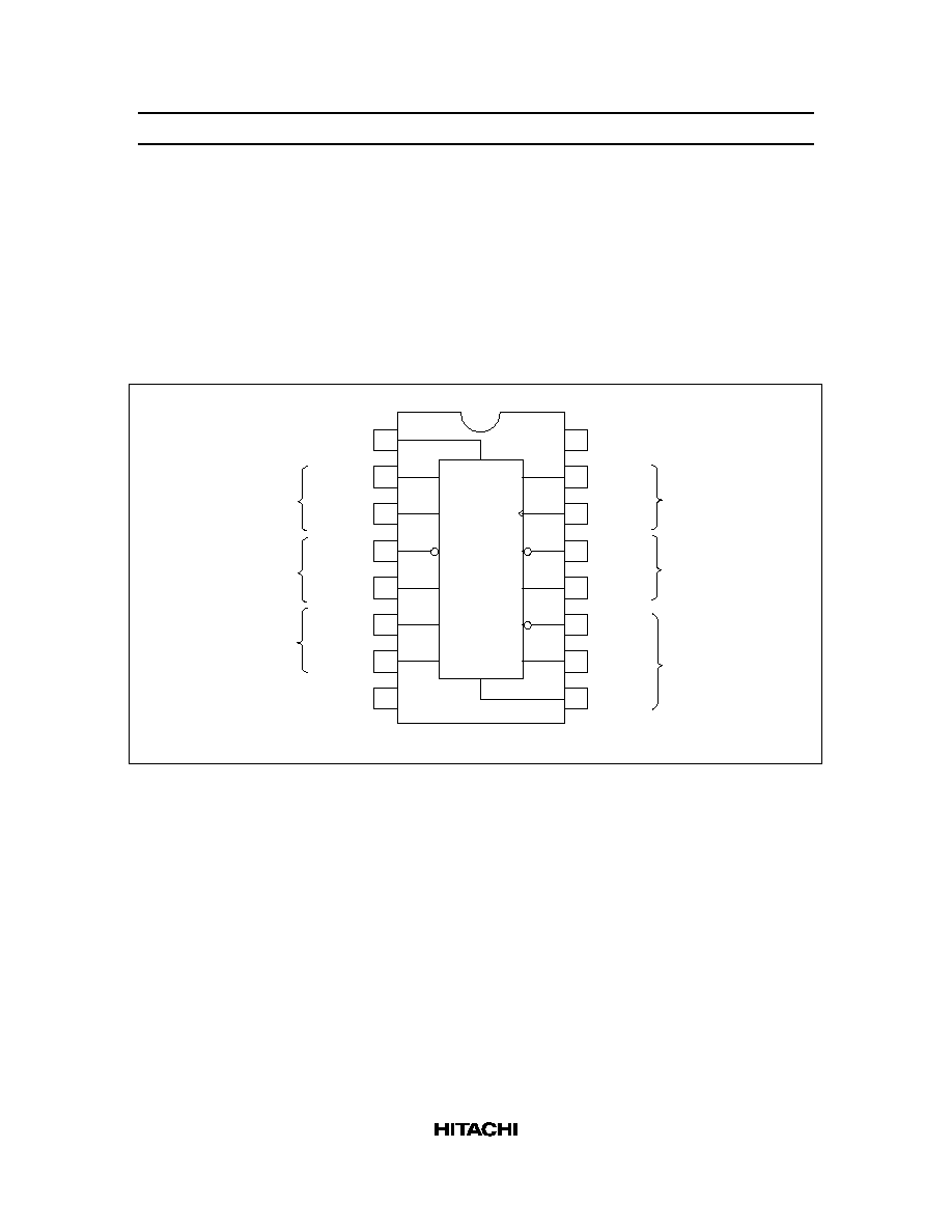
Pin Arrangement
1
2
3
4
5
6
7
8
Q
B
Q
A
Enable G
Down/Up
Q
C
Q
D
GND
V
CC
Data A
Clock
Max/Min
Load
Data C
Data D
16
15
14
13
12
11
10
9
(Top view)
Ripple
Clock
Data B
Ripple
Clock
Outputs
Outputs
Inputs
Inputs
A
CK
Max/Min
Load
C
D
Q
D
Q
C
Dn/Up
G
Q
A
Q
B
B
Inputs
Inputs
Outputs
HD74HC190/HD74HC191
3
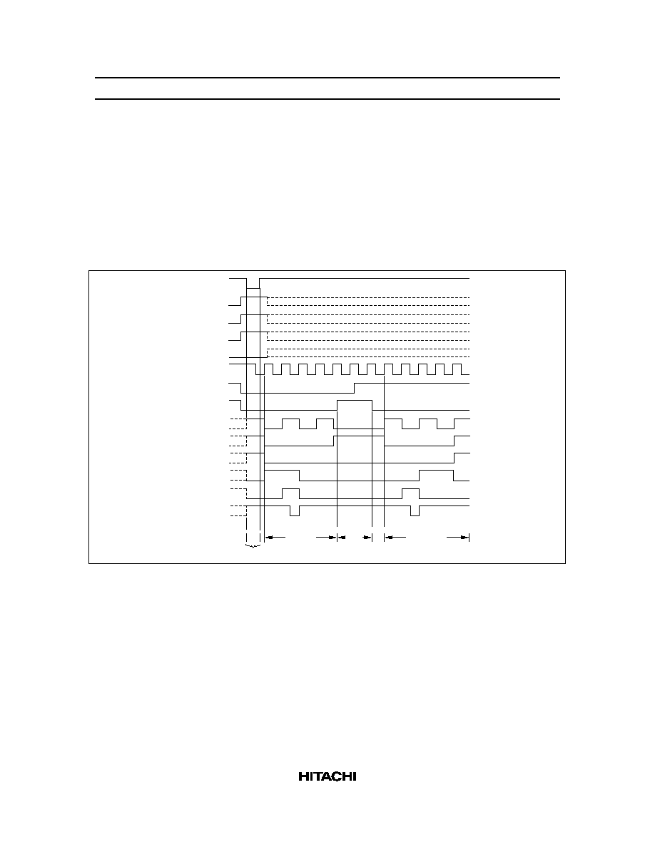
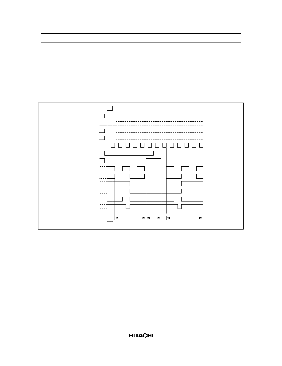
Timing Chart
HD74HC190
Illustrated below is the following sequence:
1. Load (preset) to BCD seven.
2. Count up to eight, nine (maximum), zero, one and two.
3. Inhibit
4. Count down to one, zero (minimum), nine, eight and seven.
Load
A
B
C
D
Clock
Down/Up
Enable G
Q
A
Q
B
Q
C
Q
D
Max/Min
Ripple
Clock
7
Load
8
9
0
1 2
2 2 1
0
9
8
7
Count Up
Inhibit
Count Down
HD74HC190/HD74HC191
4
HD74HC191
Illustrated below is the following sequence:
1. Load (preset) to binary thirteen.
2. Count up to fourteen, fifteen (maximum), zero, one and two.
3. Inhibit
4. Count down to one, zero (minimum), fifteen, fourteen and thirteen.
Load
A
Data
Inputs
B
C
D
Clock
Down/Up
Enable G
Q
A
Q
B
Q
C
Q
D
Max/Min
Ripple
Clock
13
Load
14
15
0
1
2
2
1
0
15
14 13
Count Up
Inhibit
Count Down