 | –≠–ª–µ–∫—Ç—Ä–æ–Ω–Ω—ã–π –∫–æ–º–ø–æ–Ω–µ–Ω—Ç: HMC-C008 | –°–∫–∞—á–∞—Ç—å:  PDF PDF  ZIP ZIP |

16
A
M
P
L
I
F
I
E
R
S
- C
O
NN
E
C
T
O
R
I
Z
E
D MOD
U
L
E
S
16 - 26
For price, delivery, and to place orders, please contact Hittite Microwave Corporation:
20 Alpha Road, Chelmsford, MA 01824 Phone: 978-250-3343 Fax: 978-250-3373
Order On-line at www.hittite.com
HMC-C008
15 WATT POWER AMPLIFIER
MODULE, 1.8 - 2.2 GHz
v00.1204
General Description
Features
Functional Diagram
The HMC-C008 is a 15 Watt Power Amplifi er
Module suitable for Cellular/3G repeaters, labora-
tory use and ATE applications. The unit includes
DC power sequencing, enable and conditioning,
as well as an output circulator for load mismatch
protection. Thermal protection/fault circuitry auto-
matically turns off DC power at base temperatures
exceeding +75 ∞C and restores power at < +55 ∞C.
P1dB Output Power: 15 Watts from 1.8 to 2.2 GH
Gain: 40 dB min
Noise Figure: 6 dB
Thermally Compensated and Protected
Reverse Polarity Protected
TTL DC Power Enable
Unconditionally Stable
Heat Sink/Fan Accessories Available
Typical Applications
Test applications for:
∑ Cellular/PCS/3G Infrastructure
∑ Automated Test Equipment (ATE)
∑ Laboratory Use
Electrical Specifi cations,
T
A
= +25∞ C, VIN = +13V to +15Vdc
Parameter
Min.
Typ.
Max.
Units
Frequency Range
1.8 - 2.2
GHz
Gain
40
42
dB
Noise Figure
6
8
dB
Input Return Loss
12
dB
Output Return Loss
12
dB
Output Power for 1 dB Compression (P1dB)
15
W
Saturated Output Power (Psat)
43
dBm
Output Third Order Intercept (IP3) (Two-tone Input Power = -28 dBm each tone)
52
dBm
Channel Output Power for -50 dBc ACPR (CDMA 2000, 1910 MHz)
36
dBm
Channel Output Power for -50 dBc ACPR (W-CDMA, 2114 MHz)
33
dBm
Second Harmonic at Output P1dB
-55
dBc
Third Harmonic at Output P1dB
-55
dBc
Spurious at Output P1dB
-65
dBc
Supply Current
6.5
7.0
A

16
A
M
P
L
I
F
I
E
R
S
- C
O
NN
E
C
T
O
R
I
Z
E
D MOD
U
L
E
S
16 - 27
For price, delivery, and to place orders, please contact Hittite Microwave Corporation:
20 Alpha Road, Chelmsford, MA 01824 Phone: 978-250-3343 Fax: 978-250-3373
Order On-line at www.hittite.com
Gain vs. Temperature
HMC-C008
v00.1204
Input & Output Return Loss
35
36
37
38
39
40
41
42
43
44
45
1.7
1.8
1.9
2
2.1
2.2
2.3
+25C
+50C
0C
GAIN
(dB)
FREQUENCY (GHz)
15 WATT POWER AMPLIFIER
MODULE, 1.8 - 2.2 GHz
-40
-35
-30
-25
-20
-15
-10
-5
0
1.7
1.8
1.9
2
2.1
2.2
2.3
Input
Output
RETURN LOSS (dB)
FREQUENCY (GHz)
P1dB vs. Temperature
Psat vs. Temperature
30
32
34
36
38
40
42
44
46
1.7
1.8
1.9
2
2.1
2.2
2.3
+25C
+50C
0C
P1dB (dBm)
FREQUENCY (GHz)
30
32
34
36
38
40
42
44
46
1.7
1.8
1.9
2
2.1
2.2
2.3
+25C
+50C
0C
Psat (dBm)
FREQUENCY (GHz)
ACPR @ 2114 MHz, W-CDMA
ACPR @ 1910 MHz, CDMA-2000
-85
-80
-75
-70
-65
-60
-55
-50
-45
-40
-35
-30
-25
-20
22
24
26
28
30
32
34
36
38
40
ACPR (dBc)
CHANNEL OUTPUT POWER (dBm)
CDMA2000 Rev. 8
Frequency : 1.96 GHz
Integration BW: 1.228 MHz
Forward Link, SRI, 9 CHANNELS
-70
-65
-60
-55
-50
-45
-40
-35
-30
-25
-20
22
24
26
28
30
32
34
36
38
40
ACPR (dBc)
CHANNEL OUTPUT POWER (dBm)
WCDMA
Frequency : 2.14 GHz
Integration BW: 3.84 MHz
64 DPCH

16
A
M
P
L
I
F
I
E
R
S
- C
O
NN
E
C
T
O
R
I
Z
E
D MOD
U
L
E
S
16 - 28
For price, delivery, and to place orders, please contact Hittite Microwave Corporation:
20 Alpha Road, Chelmsford, MA 01824 Phone: 978-250-3343 Fax: 978-250-3373
Order On-line at www.hittite.com
HMC-C008
v00.1204
Absolute Maximum Ratings
Supply Voltage (VIN)
+15.5 Vdc
RF Input Power (RFIN)
+10 dBm
Storage Temperature
-40 to +70 ∞C
Operating Temperature
0 to +50 ∞C
RF Output Isolator Max Dissipation
20 W
Thermal Fault Indicator Max Pdiss
(derate 1.8 mW/∞C above 50 ∞C)
180 mW
Enable Vmax
6 V
Output IP3 vs. Temperature
46
48
50
52
54
56
58
60
1.7
1.8
1.9
2
2.1
2.2
2.3
+25C
+50C
0C
OIP3 (dB)
FREQUENCY (GHz)
15 WATT POWER AMPLIFIER
MODULE, 1.8 - 2.2 GHz
Noise Figure vs. Temperature
Reverse Isolation vs. Temperature
-70
-60
-50
-40
-30
-20
-10
0
1.7
1.8
1.9
2
2.1
2.2
2.3
+25C
+50C
0C
ISOLATION (dB)
FREQUENCY (GHz)
0
1
2
3
4
5
6
7
8
9
10
1.7
1.8
1.9
2
2.1
2.2
2.3
+25C
+50C
0C
NOI
SE FI
GURE (dB)
FREQUENCY (GHz)
Themal Fault Indicator
Characteristics
Parameter Min.
Typ.
Max.
Units
IOUT (VOUT > 2V)
350
mA
RON (I OUT = 50 mA)
7.5
Ohms
ROFF (VOUT = 30 V)
1
µA
Enable Input Characteristics
Parameter Min.
Typ.
Max.
Units
VIH
3.5
V
VIL
1.6
V
IIL @ VIN = 0V
-0.5
mA
IIH @ 5V
< ± 50
µA
Recommended Biasing Procedure
TURN-ON
1. Connect RF input and output
2. Apply Supply Voltage VIN (+14 Vdc)
3. Set Enable low
4. Apply RF input signal
TURN-OFF
1. Remove RF input signal
2. Remove Supply Voltage VIN

16
A
M
P
L
I
F
I
E
R
S
- C
O
NN
E
C
T
O
R
I
Z
E
D MOD
U
L
E
S
16 - 29
For price, delivery, and to place orders, please contact Hittite Microwave Corporation:
20 Alpha Road, Chelmsford, MA 01824 Phone: 978-250-3343 Fax: 978-250-3373
Order On-line at www.hittite.com
HMC-C008
v00.1204
15 WATT POWER AMPLIFIER
MODULE, 1.8 - 2.2 GHz
Pin Number
Function
Description
Interface Schematic
1
RFIN &
RF Ground
RF input connector, SMA female. This pin is AC coupled
and matched to 50 Ohms from 1.8 - 2.2 GHz.
2
VIN
Power supply voltage for the amplifi er.
3
GND
Power supply ground.
4
RFOUT &
RF Ground
RF output connector, SMA female. This pin is isolator pro-
tected and matched to 50 Ohms from 1.8 - 2.2 GHz.
5
GND
Ground for thermal fault indicator and enable circuit.
6
Thermal Fault
Indicator
Open drain output. High impedance for base plate
temperatures less than 55 ∞C. Low impedance for base
plate temperatures exceeding 75 ∞C.
7
Enable
TTL compatible supply voltage (VIN) shutdown. If enable
feature is not required, short this pin to DC ground.
TTL "High" Disable
TTL "Low" Enable
Pin Descriptions
16
A
M
P
L
I
F
I
E
R
S
- C
O
NN
E
C
T
O
R
I
Z
E
D MOD
U
L
E
S
16 - 30
For price, delivery, and to place orders, please contact Hittite Microwave Corporation:
20 Alpha Road, Chelmsford, MA 01824 Phone: 978-250-3343 Fax: 978-250-3373
Order On-line at www.hittite.com
HMC-C008
v00.1204
15 WATT POWER AMPLIFIER
MODULE, 1.8 - 2.2 GHz
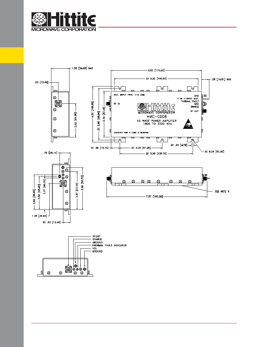
Outline Drawing
NOTES:
1. MATERIAL: ALUMINUM 6061-T6
2. FINISH
a. COVER & END PLATES, CHEMICAL FILM PER MIL-C-5541, CLASS 3
b. BASE, TIN
3. RF CONNECTORS, SMA STYLE
4. DIMENSIONS ARE INCHES (MM)
5. TOLERANCES .X±.1 (2.54mm)
.XX±.02 (0.50mm)
6. BASE MUST BE GROUNDED AND MOUNTED TO HEAT SINK
CAPABLE OF DISSIPATING 100W (50 ∞C)