
Infrared Assemblies
Dual Channel Transmissive Sensor
HOA1889 Series
Honeywell Sensing and Control
FEATURES
∑
Choice of phototransistor or
photodarlington output
∑
PCB mount package
∑
Polarized locator pins
∑
Accurate position sensing
∑
0,5 mm (0.020 in.) aperture
windows
∑
1,78 mm (0.070 in.) slot width
∑
Available in shipping tubes
The HOA1889 Series consists of two infrared emitting diodes facing
two NPN silicon phototransistors (HOA1889-011) or two photodarlington
transistors (HOA1889-013) encased in a black thermoplastic housing.
Detector switching takes place whenever an opaque object passes
through the slot between the the emitter and the detector. The dual
channels allow both the speed and the direction of the interrupter to be
sensed. Emitters and detectors have a 0,5 mm (0.020 in.) vertical
aperture. This feature is ideal for use in applications in which high
position resolution is desired.
The sensor housing is an opaque thermoplastic with aperture
openings for use in applications in which maximum rejection of ambient
light is important and maximum position resolution is desired. The
HOA1889 Series contains plastic molded components. For additional
component information see SEP8506, SDP8406, and SDP8106.
Housing material is Valox
Æ
. Housings are soluble in chlorinated
hydrocarbons and ketones. Recommended cleaning agents are
methanol and isopropanol.
Valox is a registered trademark of General Electric Company.

Infrared Assemblies
Dual Channel Transmissive Sensor
HOA1889 Series
2 Honeywell
∑
Sensing and Control
For application help: call 1-800-537-6945
ABSOLUTE MAXIMUM RATINGS (25∞C free-air temperature unless
otherwise noted)
Operating Temperature Range
-40∞C to 85∞C
Storage Temperature Range
-40∞C to 85∞C
Soldering Temperature (5 sec)
240∞C
IR EMITTER
Power Dissipation
100 mW
(1)
Reverse Voltage
3 V
Continuous Forward Current
50 mA
DETECTOR
TRANSISTOR
DARLINGTON
Collector-Emitter Voltage
30 V
15 V
Emitter Collector Voltage
5 V
5 V
Power Dissipation
100 mW
(1)
100 mW
(1)
Collector DC Current
30 mA
30 mA
Note:
1. Derate linearly at 0.78 mW/∞C above 25∞C.
CAUTION
STRESS DAMAGE
Functional operation of the device at
or above "Absolute Maximum Ratings"
for extended periods of time may
affect reliability.
Failure to comply with these
instructions may result in product
damage.
ELECTRICAL CHARACTERISTICS (25∞C unless otherwise noted)
Parameter
Symbol
Min
Typ
Max
Unit
Test Condition
IR EMITTER (each)
Forward Voltage
V
F
1.6
V
I
F
=20 mA
Reverse Leakage Current
I
R
10
µ
A
V
R
=3 V
DETECTOR (each)
Collector-Emitter Breakdown Voltage
HOA1889-011
HOA1889-013
V
(BR)CEO
30
15
V
I
C
=100
µ
A
Emitter-Collector Breakdown Voltage
V
(BR)ECO
5.0
V
I
E
=100
µ
A
Collector Dark Current
HOA1889-011
HOA1889-013
I
CEO
100
250
nA
V
CE
=10 V
I
F
=0
COUPLED CHARACTERISTICS
On-State Collector Current
HOA1889-011
HOA1889-013
I
C(ON)
0.5
2.0
mA
V
CE
=5 V
I
F
=20 mA
Collector-Emitter Saturation Voltage
HOA1889-011
HOA1889-013
V
CE(SAT)
0.4
1.1
V
I
F
=20 mA
I
C
=40
µ
A
I
C
=250
µ
A
Rise And Fall Time
HOA1889-011,
HOA1889-013
t
r
, t
f
15
75
µ
s
V
CC
=5 V, I
C
=1 mA
R
L
=1000
R
L
=100
Infrared Assemblies
Dual Channel Transmissive Sensor
HOA1889 Series
For application help: call 1-800-537-6945
Honeywell
∑
Sensing and Control 3
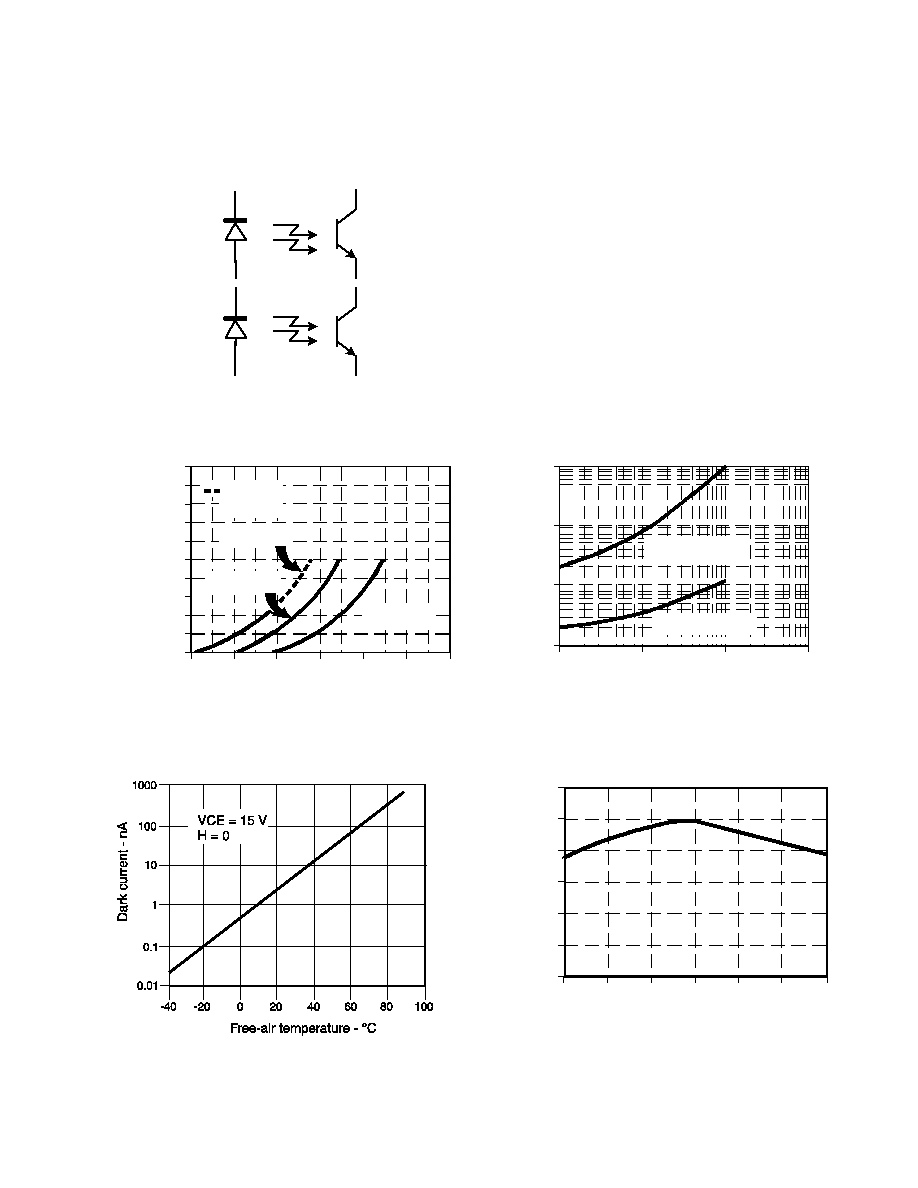
SCHEMATIC
1
2
3
4
5
6
7
8
Figure 1: IRED Forward Bias Characteristics
Forward voltage - V
F
orw
ar
d
c
ur
rent
-
m
A
0
10
20
30
40
50
60
70
80
90
100
0.8 1.0 1.2 1.4 1.6 1.8 2.0
Pulsed
condition
T
A
= 25 ∞C
T
A
= 80 ∞C
T
A
= -40 ∞C
Figure 2: Non-saturated Switching Time vs Load
Resistance
Load resistance - Ohms
R
es
p
on
s
e
ti
m
e -
µ
s
1
10
100
1000
10
100
1000 10000
Phototransistor
Photodarlington
Figure 3: Detector Dark Current vs Temperature
Figure 4: Collector Current vs Ambient
Temperature
Free-air temperature - ∞C
N
orm
ali
z
e
d
c
olle
c
t
o
r
c
urrent
0.0
0.6
1.2
-50
0.4
0.2
0.8
1.0
-25 0 25 50
100
75
Infrared Assemblies
Dual Channel Transmissive Sensor
HOA1889 Series
Sensing and Control
Honeywell Inc.
11 West Spring Street
Freeport, Illinois 61032
Printed with Soy Ink
on 50% Recycled Paper
www.honeywell.com/sensing
006457-1-EN IL50 GLO 1298 Printed in USA
ORDER GUIDE
Catalog Listing
Description
HOA1889-011
Dual Channel Transmissive Sensor, Phototransistor
HOA1889-013
Dual Channel Transmissive Sensor, Photodarlington
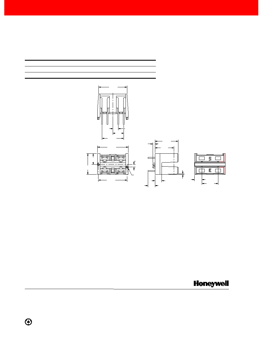
3,3
(.130)
3,18
(.125)
1,02
(.040)
10,92
(.430)
8,88
(.350)
10,16
(.400)
13,45
(.533)
14,55
(.573)
9,84
(.388)
5,08
(.200)
4
3
5
6
2x ÿ1,02
(.040)
.1,27
(.050)
2
7
1
2,54
(.100)
13,39
(.527)
5,08
(.200)
7,62
(.300)
3,45
(.136)
2.0∞
8
Leads
8. Emitter 1
7. Collector 1
5. Collector 2
4. Cathode 2
3. Anode 2
2. Cathode 1
6. Emitter 2
1. Anode 1
OUTLINE DIMENSIONS mm/(in.)
(for reference only)
WARRANTY/REMEDY
Honeywell warrants goods of its manufacture as being
free of defective material and faulty workmanship.
Contact your local sales office for warranty information. If
warranted goods are returned to Honeywell during that
period of coverage, Honeywell will repair or replace
without charge those items it finds defective. The
foregoing is Buyer's sole remedy and is in lieu of all
other warranties, expressed or implied, including
those of merchantability and fitness for a particular
purpose.
While we provide application assistance, personally,
through our literature, and through the Honeywell
website, it is up to the customer to determine the
suitability of the product in the application.
Specifications may change at any time without notice.
The information we supply is believed to be accurate and
reliable as of this printing. However, we assume no
responsibility for its use.
SALES AND SERVICE
MICRO SWITCH Sensing and Control serves its
customers through a worldwide network of sales offices
and distributors. For application assistance, current
specifications, pricing or name of the nearest Authorized
Distributor, contact a nearby sales office or call:
TELEPHONE
1-800-537-6945 (USA)
1-800-737-3360 (Canada)
1-815-235-6847 (International)
FAX
1-815-235-6545 (USA)
INTERNET
www.honeywell.com/sensing
info@micro.honeywell.com