 | –≠–ª–µ–∫—Ç—Ä–æ–Ω–Ω—ã–π –∫–æ–º–ø–æ–Ω–µ–Ω—Ç: HBT139DE | –°–∫–∞—á–∞—Ç—å:  PDF PDF  ZIP ZIP |

HI-SINCERITY
MICROELECTRONICS CORP.
Spec. No. : HE200308
Issued Date : 2003.11.01
Revised Date : 2003.11.28
Page No. : 1/4
HBT139XE
HSMC Product Specification
HBT139XE
Three Quadrant Triac
Description
Passivated, sensitive gate triacs in a plastic envelope, intended for use in
general purpose bidirectional switching and phase control applications,
where high sensitivity is required in all four quadrants.
Quick Reference Data
Part No.
V
DRM
(V)
I
T(RMS)
(A)
I
TSM
(A)
Quadrant
HBT139DE
600
16
140
I - II - III
Pin Configuration
Pin
Description
1
Main terminal 1
2
Main terminal 2
3
Gate
tab
Main terminal 2
1 2 3
tab
Symbol
T2
T1
G
Limtiing Values
Symbol
Parameter
Min.
Max.
Units
V
DRM
Repetitive peak off-state voltages
-
600
V
I
T(RMS)
RMS on-state current
-
16
A
I
TSM
Non-repetitive peak on-state current
-
140
A
I
2
t
I
2
t for fusing
-
98
A
2
S
Repetitive rate of rise of on-state current after triggering
T2+ G+
-
50
A/us
T2+ G-
-
50
A/us
T2- G-
-
50
A/us
dI
T
/dt
T2- G+
-
-
A/us
I
GM
Peak gate current
-
2
A
V
GM
Peak gate voltage
-
10
V
P
GM
Peak gate power
-
5
W
P
G(AV)
Average gate power
-
0.5
W
Tstg
Storage Temperature Range
-
150
∞
C
Tj
Operating junction temperature
-40
125
∞
C
TO-220AB

HI-SINCERITY
MICROELECTRONICS CORP.
Spec. No. : HE200308
Issued Date : 2003.11.01
Revised Date : 2003.11.28
Page No. : 2/4
HBT139XE
HSMC Product Specification
Static Characteristics
(Ta=25
∞
C)
Rank
Symbol
Parameter
Conditions
V
Unit
V
D
=6V, R
L
=10
, T2+ G+
25
mA
V
D
=6V, R
L
=10
, T2+ G-
25
mA
V
D
=6V, R
L
=10
, T2- G-
25
mA
I
GT
Gate Trigger Current
V
D
=6V, R
L
=10
, T2- G+
-
mA
V
D
=6V, R
L
=10
, T2+ G+
20
mA
V
D
=6V, R
L
=10
, T2+ G-
30
mA
V
D
=6V, R
L
=10
, T2- G-
30
mA
I
L
Latching Current
V
D
=6V, R
L
=10
, T2- G+
-
mA
I
H
Holding Current
V
D
=12V, I
GT
=0.1A
30
mA
V
T
On-state Voltage
I
T
=25A
1.5
V
V
D
=6V, R
L
=10
, T2+ G+
1.5
V
V
D
=6V, R
L
=10
, T2+ G-
1.5
V
V
D
=6V, R
L
=10
, T2- G-
1.5
V
V
GT
Gate Trigger Voltage
V
D
=6V, R
L
=10
, T2- G+
-
V
I
D
Off-state Leakage Current
V
D
=V
DRM
500
uA
Static Characteristics
Symbol
Parameter
Conditions
Min.
Typ.
Max.
Unit
dV
D
/dt
Critical rate of rise of
off-state voltage
V
DM
=67% V
DRM(max)
;
Tj= 125
∞
C; exponential
waveform; gate open circuit
-
50
-
V/us
tgt
Gate controlled turn-on
time
I
TM
=6A; V
D
=V
DRM(max)
;
I
G
=0.1A; dI
G
/dt=5A/us
-
2
-
us
Thermal Resistances
Symbol
Parameter
Conditions
Min.
Typ.
Max.
Unit
Rth j-mb
Thermal resistance junction to
mounting base
Rth j-a
Thermal resistance junction to
ambient
Full cycle
Half cycle
In free air
-
-
-
-
-
60
1.2
1.7
-
K/W
K/W
K/W
HI-SINCERITY
MICROELECTRONICS CORP.
Spec. No. : HE200308
Issued Date : 2003.11.01
Revised Date : 2003.11.28
Page No. : 3/4
HBT139XE
HSMC Product Specification
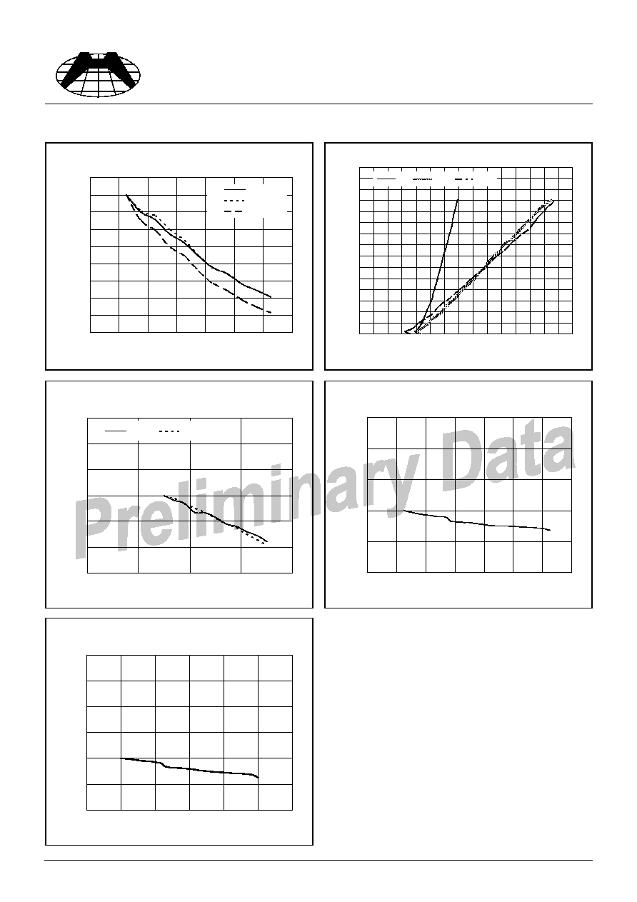
Characteristics Curve
Typical & Mmaximum On-State Characteristic
0
1
2
3
4
5
6
7
8
9
10
11
12
13
14
15
0.0 0.2 0.4 0.6 0.8 1.0 1.2 1.4 1.6 1.8 2.0 2.2 2.4 2.6 2.8 3.0
VT/V
IT
/A
typ
25∫C
125∫C
Normalised Gate Trigger Current IGT(Ta)/IGT(25
o
C),
Versus Junction Temperature Ta
0.2
0.3
0.4
0.5
0.6
0.7
0.8
0.9
1.0
1.1
0
20
40
60
80
100
120
140
Ta(
o
C)
IGT
/IGT
(
2
5
o
C)
T2+/G+
T2+/G-
T2-/G-
Normalised Gate Trigger Voltage VGT(Ta)/VGT(25
o
C),
Versus Junction Temperature Ta
0.4
0.6
0.8
1.0
1.2
1.4
1.6
-50
0
50
100
150
Ta(
o
C)
VG
T
/
VG
T
(
2
5
o
C)
T2+/G+
T2-/G-
Normalised Holding Current IH(Ta)/IH(25
o
C),
Versus Junction Temperature Ta
0.0
0.5
1.0
1.5
2.0
2.5
0
20
40
60
80
100
120
140
Ta/(
o
C)
IL
/IL
(
2
5
o
C)
Normalised Latching Current IL(Ta)/IL(25
o
C),
Versus Junction Temperature Ta
0
0.5
1
1.5
2
2.5
3
0
25
50
75
100
125
150
Ta(
o
C)
IL
/IL
(
2
5
o
C)
HI-SINCERITY
MICROELECTRONICS CORP.
Spec. No. : HE200308
Issued Date : 2003.11.01
Revised Date : 2003.11.28
Page No. : 4/4
HBT139XE
HSMC Product Specification
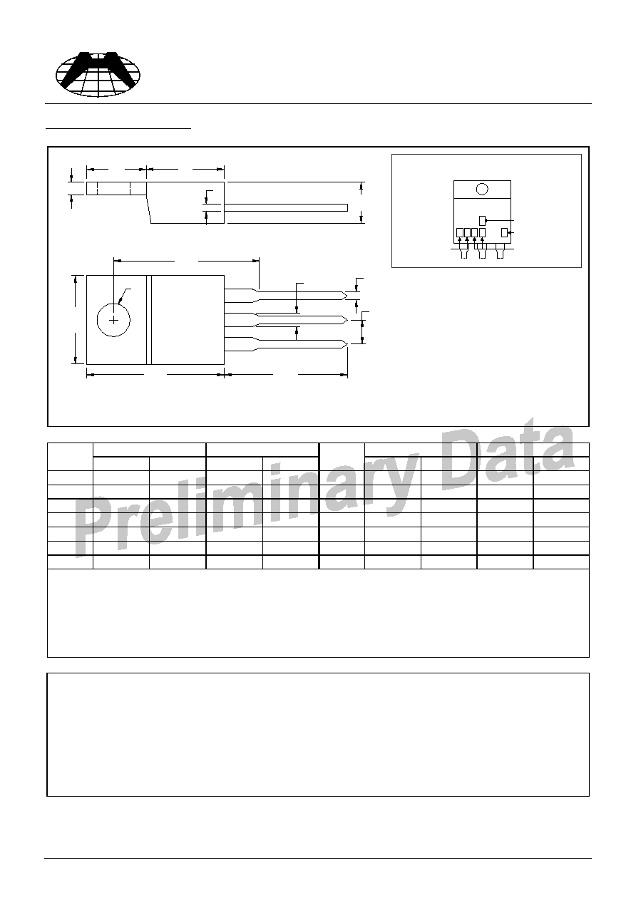
TO-220AB Dimension
*: Typical
Inches
Millimeters
Inches
Millimeters
DIM
Min.
Max.
Min.
Max.
DIM
Min.
Max.
Min.
Max.
A
0.2197
0.2949
5.58
7.49
I
-
*0.1508
-
*3.83
B
0.3299
0.3504
8.38
8.90
K
0.0295
0.0374
0.75
0.95
C
0.1732
0.185
4.40
4.70
M
0.0449
0.0551
1.14
1.40
D
0.0453
0.0547
1.15
1.39
N
-
*0.1000
-
*2.54
E
0.0138
0.0236
0.35
0.60
O
0.5000
0.5618
12.70
14.27
G
0.3803
0.4047
9.66
10.28
P
0.5701
0.6248
14.48
15.87
H
-
*0.6398
-
*16.25
Notes:
1.Dimension and tolerance based on our Spec. dated Sep. 07,1997.
2.Controlling dimension: millimeters.
3.Maximum lead thickness includes lead finish thickness, and minimum lead thickness is the minimum thickness of base material.
4.If there is any question with packing specification or packing method, please contact your local HSMC sales office.
Material:
∑
Lead: 42 Alloy; solder plating
∑
Mold Compound: Epoxy resin family, flammability solid burning class: UL94V-0
Important Notice:
∑
All rights are reserved. Reproduction in whole or in part is prohibited without the prior written approval of HSMC.
∑
HSMC reserves the right to make changes to its products without notice.
∑
HSMC semiconductor products are not warranted to be suitable for use in Life-Support Applications, or systems.
∑
HSMC assumes no liability for any consequence of customer product design, infringement of patents, or application assistance.
Head Office And Factory:
∑
Head Office (Hi-Sincerity Microelectronics Corp.): 10F.,No. 61, Sec. 2, Chung-Shan N. Rd. Taipei Taiwan R.O.C.
Tel: 886-2-25212056 Fax: 886-2-25632712, 25368454
∑
Factory 1: No. 38, Kuang Fu S. Rd., Fu-Kou Hsin-Chu Industrial Park Hsin-Chu Taiwan. R.O.C
Tel: 886-3-5983621~5 Fax: 886-3-5982931
A
B
E
G
I
K
M
O
P
3
2
1
C
N
H
D
Tab
Style: Pin 1. Main terminal 1
2. Main terminal 2
3. Gate
Tab connected to main terminal 2
3-Lead TO-220AB Plastic Package
HSMC Package Code: E
Marking:
Date Code
Control Code
H
1
B T
3 9
Rank
Serial Code