 | –≠–ª–µ–∫—Ç—Ä–æ–Ω–Ω—ã–π –∫–æ–º–ø–æ–Ω–µ–Ω—Ç: HMS30C200 | –°–∫–∞—á–∞—Ç—å:  PDF PDF  ZIP ZIP |

HMS30C2000_Preliminary V.0.9
May 31, 2001
Hynix Semiconductor Inc.
1
H
H
M
M
S
S
3
3
0
0
C
C
2
2
0
0
0
0
0
0
DVD Digital Servo & Data Processor with ATAPI
Preliminary Specification
Version 0.9,
May 31, 2001
Hynix Semiconductor Inc.

HMS30C2000_Preliminary V.0.9
May 31, 2001
Hynix Semiconductor Inc.
2
1. Introduction
P
i
c
k
°™
u
p
h
e
a
d
c
o
n
n
e
c
t
o
r
S
l
e
d
/
S
p
i
n
d
l
e
m
o
t
o
r
c
o
n
n
e
c
t
o
r
RF AMP
(RF)
Actuator
&
sled motor
driver
Spindle motor
driver
HMS30C200
0
(DP
Servo
with ATAPI)
DRAM
IDE
Interface
•Ï-Controller
Flash
Memory
Figure 1. System Diagram
1.1. HMS30C2000, u-Controller and Host.
- Host issues read-relative ATAPI command through IDE bus to HMS30C2000.
- HMS30C2000 interrupts u-Controller to decode this command.
- u-Controller sets registers according to the ATAPI command, and issues some relative DSP commands.
- HMS30C2000 demodulates and corrects the DVD or CD channel data including error terms. Then
HMS30C2000 outputs the result of ECC into DRAM buffer.
- u-Controller controls the HMS30C2000 to transfer the data from DRAM buffer through IDE bus to the
host.
1.2. RF AMP, HMS30C2000, and u-Controller
- RF AMP generates RF signals and Servo controlling signals to the HMS30C2000.
- Also RF AMP generates "laser power control signals" to pick-up head.
- RF AMP connected by serial interface with HMS30C2000.
- RF AMP outputs RF signals to HMS30C2000 pins RFO and CDRFDC.
- RF AMP outputs the RF envelop signal to HMS30C2000 pin DFT. The DFT signal is derived from
the output of the RF LPF. This signal is useful for detecting a disc defect by HMS30C2000.
RF AMP
also provides a digital defect signal to the HMS30C2000.
HMS30C2000 provides the both defect
detection mechanisms at the same time.
HMS30C2000_Preliminary V.0.9
May 31, 2001
Hynix Semiconductor Inc.
3
2. Feature
2.1. Speed performance on Servo and Decoding
°Þ DVD-P up to 2.5X
°Þ CD-Audio, CD-ROM up to 6X
°Þ Built-in a frequency programmable clock to the host interface, and the ECC decoder to optimize
the performance.
°Þ Built-in a DRAM interface programmable clock to optimize the DRAM performance and to fit all
types of DRAM.
2.2. Channel Data Processor for DVD and CD
°Þ Provide a serial interface with the RF AM1 RF chip.
°Þ Digital Data slice for adaptive jitter control.
°Þ EFM/EFM+ data demodulation
°Þ Enhanced channel data frame sync protection
°Þ Enhanced the DVD sector sync protection
°Þ Advanced PRML for Data recovery
2.3. Spindle Motor Control
°Þ Provides the programmable frequency error gain and phase error gain of spindle motor on CLV
mode and CAV mode.
°Þ Provides a speed control using digital servo firmware for CLV and CAV mode.
2.4. Servo Control
°Þ Built-in ADCs and DACs for digital servo control.
°Þ Provides two general multi-level PWM/digital outputs and a general ADC input.
°Þ Built-in DSP for the digital servo control including the following functions:
- Programmable digital filters to cover the wide range of servo characteristics.
- Focusing servo loop
- Tracking servo loop(including a run-out compensator)
- Sled motor servo loop
- Auto calibration after servo initialization
- Shock/Defect detection and protection
- Unbalance detection
- Run out detection
- Photo interrupter auxiliary detection
- Actuator central servo loop
°Þ Built-in DACs to interface the external actuators and has a PWM to interface to the driver of the
spindle motor.
2.5. Host Interface
°Þ Directly connected bus pins without external TTL components.
°Þ Provides a licensed CSS(Content Scramble System) protection.
°Þ Enhanced-IDE(ATAPI) host interface.
°Þ Built-in a 16-word input data/ATAPI Packet Command FIFO.
°Þ Built-in a 64-word host output data FIFO.
°Þ Supports an ATA/ATA-2 PIO(Programmed Input/ Output) data transfer mode and multi word-DMA
data transfer mode.

HMS30C2000_Preliminary V.0.9
May 31, 2001
Hynix Semiconductor Inc.
4
°Þ Supports an ATA/ATA-4 Ultra DMA transfer mode with data rate up to 33Mbytes/sec.
°Þ Intelligent automated target sector search.
°Þ Provides hardware macros to accelerate the ATAPI command processing.
°Þ Multi block data transfer with the automatic ATA Task File Registers handling.
°Þ Automatic sector data transfer to Host in PIO, DMA or UDMA mode.
°Þ Selective transfer of sectors Sync, Header, User Data, ECC/EDC, Error flags, and Subcode data with
automatic transfer length calculation and buffer address manipulations.
°Þ Provides programmable buffering counter for buffer status tracking.
°Þ Provides Local bus interface (Jumbo for DVS, SSI for Samsung with C-Cube)
2.6. •Ï-Controller Interface
°Þ Supports multiple accessing types of the u-controller:
- Type1: Both the data bus and the address bus are multiplexed on the same pins like as the Intel 8032
•Ï-controller.
- Type2: Data bus and address bus are separated as the Hitachi H8 •Ï-controller.
°Þ Provides 2 banks of 256 registers and uses one pins to address the banks. One bank is used for the
•Ï-controller external memory.
°Þ Provides pins GPIO[7:0] for monitoring or GPIO function.
°Þ Provides a clock drive to the •Ï-controller (33.8688 or 16.9344 MHz)
°Þ Supports an IDE flash mode controller.
°Þ Provides 24-bit by 24-bit multiplication and division unit to reduce the •Ï-controller load.
2.7. CD-DA(C1/C2) Decoding Logic
°Þ Provides a powerful error mechanism to correct quadruple errors for C1 and C2.
°Þ Provides the capability of °æ8 frame jitter margin.
°Þ Two 16-bit error pointer counters for C1 and C2 respectively can be read by the •Ï-controller.
°Þ Error correction monitor signals can be output through programmable I/O pins.
2.8. CD-ROM(Video CD) Decoding Logic
°Þ Supports CD-ROM mode1, CD-ROM XA mode2 form1/form2, and CD-DA formats.
°Þ Concurrent DSP data transfer, error correction, and host data transfer operation at up to 6X speed.
°Þ High speed ECC logic capable of correcting one error per each P-codeword or Q-codeword.
°Þ Provides the automatic sector mode and form detection.
°Þ Provides the automatic sector header verification.
°Þ Provides an 8-bit counter for decode completion check.
°Þ Programmable descrambling and error correction schemes.
°Þ Provides Decoder Error Notification Interrupt that signals various decoder errors.
2.9. DVD Decoding Logic
°Þ Concurrent DSP data transfer, error correction, and host data transfer operation at up to 2.5X speed.
°Þ Provides a powerful ECC error correcting mechanism to correct 10 PI errors and 16 PO errors.
°Þ Provides error correction acceleration.
°Þ Provide Decoder Error Notification Interrupt that signals various decoder errors.
°Þ PI error correction monitor signals output through programmable I/O pins.
°Þ Provides a 16-bit PI error counter pointer that can be read by the •Ï-controller.

HMS30C2000_Preliminary V.0.9
May 31, 2001
Hynix Semiconductor Inc.
5
2.10. Buffer Memory Controller
°Þ Supports up to 1M-word 3.3Volt Fast-page/EDO mode DRAM buffer or 2 banks 1-M word SDRAM.
°Þ Supports Fast-page/EDO DRAMs of 8~11 bit column address.
°Þ Built-in a DRAM interface programmable clock to optimize the DRAM performance.
°Þ EDO can provide the DRAM bandwidth required on 2.5X DVD.
°Þ Provides high bandwidth of SDRAM for the maximum 2.5X speed DVD.
°Þ Provides self-refresh mode for EDO and SDRAM to reduce power consumption.
°Þ Provides programmable DRAM access cycle and refresh cycle timings.
°Þ Block based sector addressing.
2.11. Audio Processing
°Þ Supports audio playback from DRAM buffer.
°Þ Register selectable audio reference clock frequency.
°Þ Programmable audio output format.
°Þ Provides IEC-958 Consumer Digital Audio Output.
°Þ Separate left and right channels routing and muting controls.
2.12. Power Down Mode
°Þ Whole chip power-down modes support, include sleep mode and standby mode.
°Þ The •Ï-controller, ECC decoder, Servo DSP and partial IDE interface or Local bus interface can be
power down individually.
2.13. Outline
°Þ 208-pin TQFP package.

3. Block Diagram
RFZC
TEZC
Circuit
RF Flag
Interface
Data
Slicer
Data
PLL
Servo
ADC
Serial RF
Controller
PDM &
PWM
DAC
Flags &
Program
-mable
I/O
Servo
DSP
Sync
Protection
EFM/EFM+
Demodulator
Subcode/ID
Demodulator
CLV/CAL
Controller
DAC
FG
Sensing
CLV Clock
Generator
CIRC/RSPC
Error
Corrector
CD-ROM
SyncDetection
Descrambler
C3
Decoder
System
Clock
Generator
DRAM
Clock
Generator
Audio
Effect
Interface
CD-ROM
High-speed
Audio
Playback
CSS
Host
Data
FIFO
ATAPI
Packet
FIFO
Host MPEG Interface
•Ï
-controller
Interface
Buffer
Memory
Controller
Audio
Digital Out
System Clock
Reset
Logic
MIRROR
TZC
DFCTI
ADCVDD
FEI
TEI
RFRP
SBAD
VREFI
ADIN
ADCVSSI
CM,REF
REFBIAS
RFSCLK
RFSEN
RFSIO
FOO
TRO
FMO
PWMOUT1
PWMOUT2
DAVDD
DAVSS
GPIO[7:0]
T_DIN
T_CLK
T_DRZ
T_DOUT
T_ST0
T_ST1
T_ST2
SRST
RA[10:0]
RASZ
CASZ
DWRZ
DQM
CLK
BA
VDD
VSS
PRSTZ
DD[15:0]
U
A
D
7
:
0
U
R
S
T
Z
U
I
N
T
Z
U
W
R
Z
U
C
S
2
U
C
S
1
U
A
L
E
U
A
6
:
0
U
R
D
Z
I
O
C
S
1
6
Z
I
N
T
R
Q
I
O
R
D
Y
D
M
A
R
Q
C
S
3
F
X
Z
C
S
1
F
X
Z
H
A
2
:
0
D
M
A
C
K
Z
D
I
O
R
Z
D
I
O
W
Z
H
R
S
T
Z
D
A
S
P
Z
P
D
I
A
G
Z
H
D
1
5
:
0
C
D
_
9
5
8
C
D
B
C
K
C
D
L
R
C
K
C
D
D
A
O
C
D
C
2
P
O
C
D
3
8
4
f
D
M
O
F
G
R
E
F
F
G
I
N
P
G
R
E
F
P
G
I
N
J
i
t
t
e
r
O
A
V
S
S
V
R
B
V
R
T
A
V
D
D
R
F
I
B
D
O
U
R
S
T
Z
A
P
L
L
V
S
S
A
P
L
L
V
D
D
C
K
3
3
I
P
L
L
V
S
S
P
L
L
V
D
D
X
T
A
L
I
X
T
A
L
O
C
K
3
3
O
HMS30C2000 Block Diagram for Data Processor & Servo
T
S
T
M
D
T
S
C
A
N
T
E
S
T
O
7
:
0
Hynix Semiconductor Inc.
HMS30C2000_Preliminary Spec.
V.0.9
May 31, 2001
6
HMS30C2000_Preliminary V.0.9
May 31, 2001
Hynix Semiconductor Inc.
7
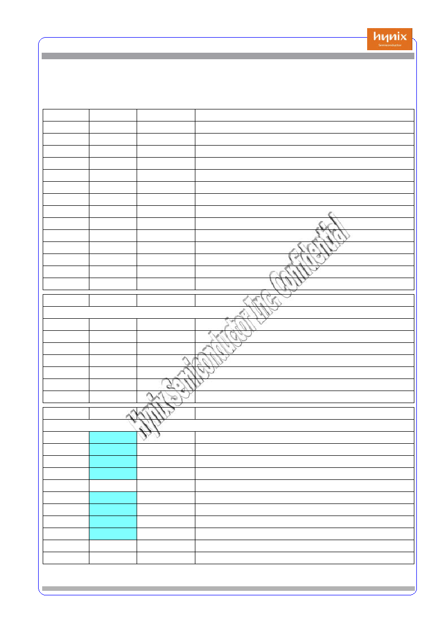
4. Pin Allocation
Pin Description Table
Pin Number Symbol
Type
Description
29
u_Com
41
DRAM
45
Host
30
Servo Glue
7
Analog I/O
20
ADC
11
DAC
10
Etc (PLL, Clock)
1
PRSTZ
Digital INPUT
Power On Reset
1
TSTMD
Test Mode
1
TSCAN
Test Scan
4
DVDD,VSS
Ref Power.
8
TESTO[7:0]
Digital Output
Test Monitoring
208
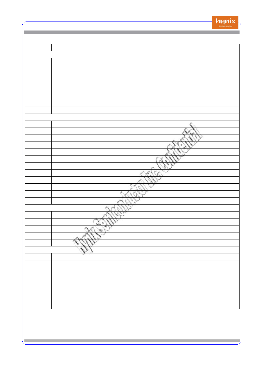
Pin Number Symbol
Type
Description
JTAG Interface
EMU0
TTL I/O/Z, PU
Emulator Pin 0
EMU1
TTL I/O/Z, PU
Emulator Pin 1
TRST
TTL Input, PD
IEEE Standard Test Reset
TMS
TTL Input, PD
IEEE Standard Test Mode Select
TDO
TTL O/Z
IEEE Standard Test Data Output
TDI
TTL Input, PU
IEEE Standard Test Data Input
TCK
TTL Input, PU
IEEE Standard Test Clock
Pin Number Symbol
Type
Description
u-Controller Interface
1
UALE/UA7
TTL sc I/O
Address Latch Enable or uP Address Bit 7
8
UAD[7:0]
TTL Digital I/O uP Address/Data Bus
1
UCS2
"
,
PU
uP Chip Sel2 for internal SRAM
1
UCS1
"
,
PU
uP Chip Sel1 for internal Register
7
UA[6:0]
"
,
PU
uP Address Bus
1
UWRZ
TTL sc I PU
uP Write Strobe
1
URDZ
TTL sc I PU
uP Read Strobe
0
URST
Digital Output
Reset signal output
1
UINTZ
Digital Output
uP Interrupt
8
VDD,VSS
Power Pins
29

HMS30C2000_Preliminary V.0.9
May 31, 2001
Hynix Semiconductor Inc.
8
Pin Description Table
Pin Number Symbol
Type
Description
Memory Interface
1
DQM
TTL I/O
SDRAM Input/Output Mask
1
BA
Digital Output
SDRAM Bank Address
1
CLK
Digital Output
SDRAM Clock
11
RA[10:0]
Digital Output
DRAM Address Bus
1
RASZ
Digital Output
DRAM Row Address Storbe
1
DWRZ
Digital Output
DRAM Write Enable
1
CASZ
Digital Output
DRAM Column Address Strobe
16
DD[15:0]
Digital I/O
DRAM Data Bus
8
VDD,VSS
Power Pins
41
Host Interface
1
DASPZ
TTL D I/O, PU Drive Active / Slave Present
1
CS3FXZ
TTL sc DI, PU Host Chip Select 2 ( for 3Fxh/37xh)
1
CS1FXZ
TTL sc DI, PU Host Chip Select 1 ( for 1Fxh/17xh)
3
HA[2:0]
TTL sc DI, PU Host Address Bus
1
PDIAGZ
TTL D I/O, PU Passed Diagnostics
1
IOCS16Z
Digital Output
I/O 16 bit Chip Select
/ ValidO
1
INTRQ
Digital Output
Host Interrupt
/
TOSO
1
DMACKZ
TTL sc DI, PU DMA Acknowledge
/ DREQZ
Data Req. from u-Com
1
IORDY
Digital Output
I/O Channel Ready
/
DTCLKO
1
DIORZ
TTL sc DI, PU Drive I/O Read
1
DIOWZ
TTL sc DI, PU Drive I/O Write
1
DMARQ
Digital Output
DMA Request
/
DTERRO
16
HD[15:0]
Digital I/O
Host Data Bus
/
A/V interface Data Output(7:0)
1
HRSTZ
TTL sc Input
Host Reset
8
VDD, VSS
Power Pins
1
CD_BCK
Digital Output
Bit Clock
1
CD_LRCK
Digital Output
L/R Clock
1
CD_DAO
Digital Output
Serial Data
1
CD_C2PO
Digital Output
C2PO Indicator
1
CD_384fs
Digital Output
CD_Ref Clock
1
CD_958
Digital Output
CD Digital Out based on IEC958
45
HMS30C2000_Preliminary V.0.9
May 31, 2001
Hynix Semiconductor Inc.
9
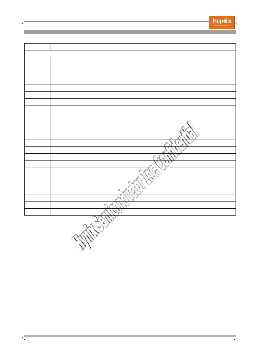
Pin Description Table
Pin Number Symbol
Type
Description
Analog Interface
1
FGREF
TTL hs Input
FG Ref. Clock Input
1
FGIN
TTL hs Input
FG Signal Input
1
PGREF
TTL hs Input
PG Ref. Clock Input
1
PGIN
TTL hs Input
PG Signal Input
1
TZC
TTL hs Input
Track Ref. Signal Input
1
MIRROR
TTL hs Input
Track Signal Input
1
DFCTI
TTL hs Input
Defect Input for detecting a defect
7
Analog Interface for ADC (10 bit & 6 bit)
6
ADIN[5:0]
Analog Input
DMA Acknowledge
1
CM
Analog Input
Connect Ext 0.75V
1
REFBIAS1
Analog I/O
Connect Ext 2.1V
1
REF
Analog I/O
Connect Ext 2.1V
2
AVDD,GND
Analog Power
Analog Power
2
DVDD,GND
Digital Power
Digital Power
1
VIN_RF
Analog Input
Host Reset
1
VRB
Reference Bottom
1
VRT
Reference Top
2
AVDD,GND
Analog Power
Analog Power
2
DVDD,GND
Digital Power
Digital Power
20
Analog Interface for DAC
2
AVDD,GND
Analog Power
Analog Power
2
DVDD,GND
Digital Power
Digital Power
4
AOUT[3:0]
Analog Output
FOO, TRO, VREFO, DMO
3
PWM[2:0]
Digital Output
PWM Output [2:0]
11
Analog PLL
2
AVDD,GND
Analog Power
Analog Power
2
DVDD,GND
Digital Power
Digital Power
1
XTALI
Crystal Input
1
XTALO
Crystal Output
1
CK33IN
Clock Input
2
DVDD,GND
Digital Power
Digital Power
1
CLKOUT
Clock Output
u-Com Clock Output
10
HMS30C2000_Preliminary V.0.9
May 31, 2001
Hynix Semiconductor Inc.
10
Pin Description Table
Pin Number Symbol
Type
Description
Servo DSP Program Down Load &General Purpose I/O
1
E_SIN
Digital Input
Servo DSP PGM Downloading Data Input
1
E_CLK
Digital Input
Servo DSP PGM Downloading Clock
1
E_DRZ
Digital Output
Servo DSP PGM Downloading Direction
1
E_SOUT
Digital Output
Servo DSP PGM Downloading Data Output
3
E_ST[2:0]
Digital Output
Servo DSP PGM Downloading Status[2:0]
1
GPOI7
Digital I/O
Servo DSP General I/O : FSON (Focus On Inverting)
1
GPOI6
Digital I/O
Servo DSP General I/O : PSEL
1
GPOI5
Digital I/O
Servo DSP General I/O : ADADDR3
1
GPOI4
Digital I/O
Servo DSP General I/O : FKRST
1
GPOI3
Digital I/O
Servo DSP General I/O : FKSET
1
GPOI2
Digital I/O
Servo DSP General I/O : FEL
1
GPOI1
Digital I/O
Servo DSP General I/O
1
GPOI0
Digital I/O
Servo DSP General I/O : DSP_SENSE
1
JitterO
Digital Output
Jitter Monitoring Out (Using PWM)
8
VDD, VSS
Digital Power
Power Pins for Digital Circuits
1
RFSIO
TTL Input
RF Serial Data I/O interface
1
RFSEN
Digital Output
RF Serial Interface Enable
1
RFSCLK
Digital Output
RF Serial Interface Clock
1
SRST
Digital Input
Servo Part Hardware Reset
30

HMS30C2000_Preliminary V.0.9
May 31, 2001
Hynix Semiconductor Inc.
11
5. DC Characteristics
5.1.1. Absolute Maximum Ratings
Symbol
Parameter
Rating
Units
VDD
Power Supply
-0.3 ~ 3.6
V
VIN
Input Voltage
-0.3 ~ VDD
V
VOUT
Output Voltage
-0.3 ~ VDD
V
Tstg
Storage Temperature
-40 to 125
°…
5.1.2. Recommended Operating Conditions
Symbol
Parameter
Min
Typ
Max
Units
VDD
Power Supply
3.0
3.3
3.6
V
VIN
Input Voltage
0
VDD
V
VOUT
Output Voltage
0
VDD
V
Topr
Operating Temperature
-40
85
°…
5.1.3. General DC Characteristics
Symbol
Parameter
Conditions
Min
Typ
Max
Units
IIL
Input low current
No pull_up or
down
-1
1
ßÀ
IIH
Input high current
"
-1
1
ßÀ
IOZ
Tri-state leakage
current
-10
10
ßÀ
CIN
Input capacitance
3
ßÐ
COUT
Output capacitance
3
ßÐ
CBID
Bidirectional buffer
capacitance
3
ßÐ
5.1.4. DC Electrical Characteristics
Symbol
Parameter
Min
Typ
Max
Units
RFI
Input Frequency
200KHz
6~12MHz
15MHz
MHz
RD
Operating Frequency
4
8M
16M
Mword/s
SCLK
Servo DSP Clock
45.1584
MHz
mck
Internal system clock
67.7376
MHz