
1 10/02/98
SigmaTel, Inc.
Integrating Mixed-Signal Solutions
STAC9704/7
Multimedia Audio Codec for AC'97
GENERAL DESCRIPTION:
SigmaTel's STAC9704/07 is a general purpose 18-bit, full duplex, audio codec that conforms to the analog
component specification of AC'97 (Audio Codec '97 Component Specification rev. 1.03). The
STAC9704/07
incorporates SigmaTel's
proprietary Sigma-Delta technology to achieve signal quality in excess of 95dB SNR.
The DACs, ADCs, and mixers are integrated with analog I/Os, which include four analog line-level stereo inputs,
two analog line-level mono inputs, and 3 output channels. Also included are SigmaTel's 3D stereo enhancement
(SS3D) and an extra true line-level out for headphones or speaker amplifiers. The
STAC9704/07 communicates
via the five wire AC Link to any digital component of AC'97 providing flexibility in the audio system design.
Packaged in a small AC'97 compliant 48-pin TQFP, the
STAC9704/07 can be placed on the motherboard,
daughter boards, add-on cards, PCMCIA cards, or outside the main chassis such as in a speaker. The 9707 is
identical to the 9704 except that the 9707 is tested at AVdd = DVdd = 3.3V.
FEATURES:
�
High performance
technology
�
18-bit full duplex stereo A/D, D/A
�
AC-link protocol compliance
�
Single power source from 5V to 3.3V
�
AC'97 compliant mixer
�
SigmaTel Surround (SS3D)
Stereo
Enhancement
�
Energy saving power down modes
�
48k sample/second rate
�
Six analog line-level inputs
�
48-pin TQFP
�
SNR > 95 dB through Mixer and DAC
�
STAC9707 is the 3.3 volt version
2
10/02/98
ORDERING INFORMATION:
PART
NUMBER
PACKAGE
TEMPERATURE
RANGE
SUPPLY RANGE
STAC9704T
48-pin TQFP 7mm x 7mm x 1.4mm
0o C to +70o C
DVdd = 3.3V � 5V, AVdd = 5V
STAC9707T
48-pin TQFP 7mm x 7mm x 1.4mm
0o C to +70o C
DVdd = 3.3V AVdd = 3.3V
SigmaTel reserves the right to change specifications without notice.

SigmaTel, Inc
STAC9704/7
3
10/02/98
Table of Contents
General Description
1
Ordering Information
2
1. PIN/SIGNAL Descriptions
8
1.1 Digital I/O
8
1.2 Analog I/O
9
1.3
Filter and Voltage References
10
1.4
Power and Ground Signals
11
2. AC-Link
11
2.1 Clocking
12
2.2 Reset
12
3. Digital Interface
12
3.1 AC-link Digital Serial Interface
Protocol
12
3.1.1 AC-link Audio Output Frame
(SDATA_OUT)
14
3.1.1.1 Slot 1: Command Address Port
16
3.1.1.2 Slot 2: Command Data Port
16
3.1.1.3 Slot 3: PCM Playback Left
Channel
16
3.1.1.4 Slot 4: PCM Playback Right
Channel
17
3.1.1.5 Slots 5-12: Reserved.
17
3.1.2 AC-link Audio Input Frame
(SDATA_IN)
17
3.1.2.1 Slot 1: Status Address Port
19
3.1.2.2 Slot 2: Status Data Port
19
3.1.2.3 Slot 3: PCM Record Left
Channel
19
3.1.2.4 Slot 4: PCM Record Right
Channel
19
3.1.2.5 Slots 5-12: Reserved
20
3.2 AC-link Low Power Mode
20
3.2.1 Waking up the AC-Link
21
4. STAC9704/7 Mixer
21
4.1 Mixer Input.
23
4.2 Mixer Output
23
4.3 PC Beep Implementations
23
4.4 Mixer Registers
24
4.4.1 Reset Register
25
4.4.2 Play Master Volume Registers
25
4.4.3 PC Beep Register
25
4.4.4 Analog Mixer Input Gain
26
4.4.5 Record Select Control
26
4.4.6 Record Gain Registers
28
4.4.7 General Purpose Register
28
4.4.8 3D Control Register
29
4.4.9 Powerdown Control/Status
29
5. Low Power Modes
30
6. Testability
32
7. AC Timing Characteristics
32
7.1 Cold Reset.
32
7.2 Warm Reset
33
7.3 Clocks
34
7.4 Data Setup and Hold
35
7.5 Signal Rise and Fall Times
36
7.6 AC-link Low Power Mode Timing
36
7.7 ATE Test Mode
37
8. Electrical Specifications
38
8.1 Absolute Maximum Ratings
38
8.2 Recommended Operating Conditions 38
8.3 Power Consumption
39
8.4 AC link Static Digital Specifications 39
8.5
9704 Analog Performance
Characteristics
40
8.6
9707 Analog Performance
Characteristics
42
APPENDIX A
44
APPENDIX B
45

SigmaTel, Inc
STAC9704/7
4
10/02/98
Table of Contents � Tables
Table 1 � Package Dimensions
5
Table 2 � Pin Designation
5
Table 3 � Digital Signal List
8
Table 4 � Analog Signal List
9
Table 5 � Filtering and Voltage References
10
Table 6 �Power Signal List STAC9704/07
11
Table 7
Table 8 � Mixer Functional Connections
22
Table 9 � Mixer Registers
24
Table 10 � Play Master Volume Register
25
Table 11 � PC Beep Register
26
Table 12 � Analog Mixer Input Gain Register
26
Table 13 � Record Select Control Registers
27
Table 14 � Record Gain Registers
28
Table 15 � General Purpose Register
28
Table 16 � 3D Control Register
29
Table 17 � Powerdown Status Register
30
Table 18 � Low Power Modes
30
Table 19 � Cold Reset
32
Table 20 � Warm Reset
33
Table 21 � Clocks
34
Table 22 � Data Setup and Hold
35
Table 23 � Signal Rise and Fall Times
36
Table 24 � AC-link Low Power Mode Timing
37
Table 25 � ATE Test Mode
37
Table 26 � Operating Conditions
38
Table 27 � Power Consumption
39
Table 28 � AC-link Static Specifications
39
Table 29 � 9704 Analog Performance
Characteristics
40
Table 30 � 9707 Analog Performance
Characteristics
42
Table of Contents � Figures
Figure 1 � Package Outline
5
Figure 2 � STAC9704 Block Diagram
6
Figure 3 � Connection Diagram
7
Figure 4 � STAC9704/07 AC'97 Link
11
Figure 5 � AC'97 Bi-directional Audio Frame
14
Figure 6 � AC-link Audio Output Frame
15
Figure 7 � Start of an Audio Output Frame
15
Figure 8 � STAC9704/07 Audio Input Frame
18
Figure 9 � Start of an Audio Input Frame
18
Figure 10 � STAC9704 Powerdown Timing
20
Figure 11 � STAC9704/07 Mixer Functional Diagram 22
Figure 12 � Example of STAC9704/07 Powerdown/
Powerup flow
31
Figure 13 � STAC9704/07 Powerdown/Powerup
with analog still alive
31
Figure 14 � Cold Reset
32
Figure 15 � Warm Reset
33
Figure 16 � Clocks
34
Figure 17 � Data Setup and Hold
35
Figure 18 � Signal Rise and Fall Times
36
Figure 19 � AC-link Low Power Mode Timing
36
Figure 20 � ATE Test Mode
37
SigmaTel, Inc
STAC9704/7
5
10/02/98
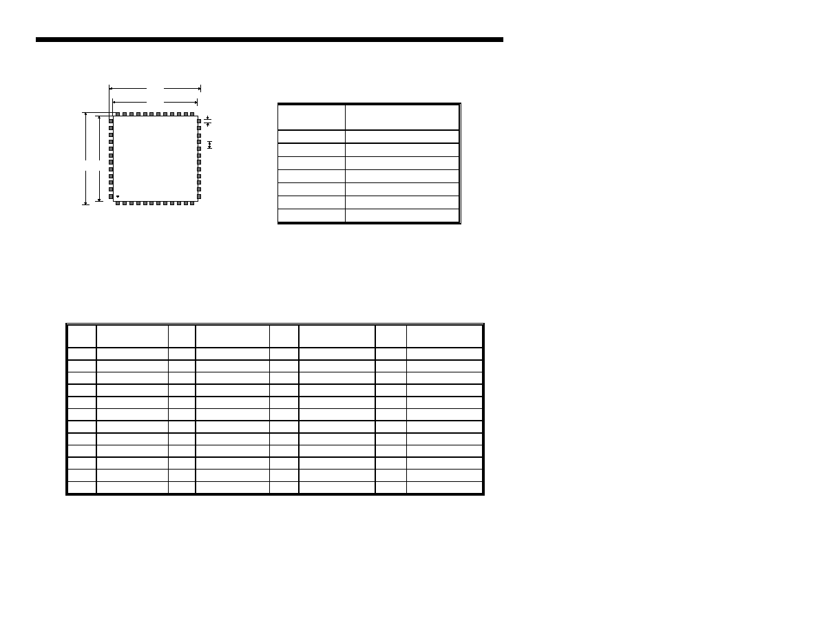
Figure 1 � Package Outline
SigmaTel
STAC9704/7
48 pin TQFP
a
D1
D
e
E1
E
38
26
14
2
Table 1 - Package Dimensions
KEY
9704/7 DIMENSION
TQFP
D
9.00 mm
D1
7.00 mm
E
9.00 mm
E1
7.00 mm
a (lead width)
0.20 mm
e (pitch)
0.50 mm
thickness
1.4 mm
Table 2 - Pin Designation
PIN
#
SIGNAL
NAME
PI
N #
SIGNAL
NAME
PIN
#
SIGNAL
NAME
PIN
#
SIGNAL
NAME
1
DVdd1
13
PHONE
25
AVdd1
37
MONO_OUT
2
XTL_IN
14
AUX_L
26
AVss1
38
AVdd2
3
XTL_OUT
15
AUX_R
27
Vref
39
LNLVL_OUT_L
4
DVss1
16
VIDEO_L
28
Vrefout
40
NC
5
SDATA_OUT
17
VIDEO_R
29
AFILT1
41
LNLVL_OUT_R
6
BIT_CLK
18
CD_L
30
AFILT2
42
AVss2
7
DVss2
19
CD_GND
31
NC
43
NC
8
SDATA_IN
20
CD_R
32
CAP2
44
NC
9
DVdd2
21
MIC1
33
NC
45
NC
10
SYNC
22
MIC2
34
NC
46
NC
11
RESET#
23
LINE_IN_L
35
LINE_OUT_L
47
NC
12
PC_BEEP
24
LINE_IN_R
36
LINE_OUT_R
48
NC
# denotes active low