 | –≠–ª–µ–∫—Ç—Ä–æ–Ω–Ω—ã–π –∫–æ–º–ø–æ–Ω–µ–Ω—Ç: iC-WE | –°–∫–∞—á–∞—Ç—å:  PDF PDF  ZIP ZIP |

iC-WE
3-CHANNEL 75 LINE DRIVER
Rev D1, Page 1/10
SO20
TSSOP20
thermal pad
SO16W
FEATURES
APPLICATIONS
À
3 current-limited and short-circuit-proof push-pull drivers
À
Built-in adaption to 75 characteristic impedance
À
High driver current of 300 mA at 24 V typ.
À
Low saturation voltage up to 30 mA load current
À
Short switching times and high slew rates by npn circuitry
À
Wide driver supply range VB = 4.5 V to 30 V
À
Internal free-wheeling diodes to VB and GND
À
Schmitt trigger inputs with integrated pull-up current sources
À
Inputs compatible to TTL and CMOS
À
Inverting and non-inverting driver mode
À
Bus capability due to Tri-State switching
À
Compatible to EIA standard RS-422
À
Thermal shutdown with hysteresis
À
Short-circuit-proof OC error output reports thermal shutdown
or undervoltage at VCC or VB
À
Driver disabled in case of fault
À
extended temperature range of up to 130 ∞C in
TSSOP20tp 4.4 mm package
À
24 V signal transfer
À
Line driver in PLC environment
PACKAGES
BLOCK DIAGRAM
Copyright © 2003, iC-Haus
www.ichaus.com
iC-WE
SO20
LOW VOLTAGE
T.SHUTDOWN
ERROR
CHAN 3
CHAN 2
CHAN 1
MODE
GND
4-7,14-17
A3
18
A2
13
A1
11
NER
3
VB
12
VCC
2
TNER
10
TRI
8
INV
9
E1
1
E3
19
E2
20

iC-WE
3-CHANNEL 75 LINE DRIVER
Rev D1, Page 2/10
SO20
SO16W
(low power applications only)
TSSOP20tp 4.4 mm
DESCRIPTION
The iC-WE is a high-speed monolithic line driver circuit for three independent channels with built-in
characteristic impedance adaption for 75 lines. The push-pull outputs are designed for a high driver power
of typ. 300mA at 24V. They are current-limited and short-circuit protected by thermal shut-down at over-
temperature. Clamp diodes to VB and to GND protect the IC outputs against echoes of mismatched lines and
against damage due to ESD according to MIL-STD-883.
All inputs are Schmitt triggers and contain current sources from the 5V supply VCC which select a defined
High Level without external wiring. Clamp diodes to VCC and to GND furnish ESD protection.
Using the INVert input it is possible to switch all channels to inverting or non-inverting operation. This enables
a data transmission with balanced line activation using two iC-WE devices. For bus applications the final
stages can be forced to a high impedance state using the TRI-State input.
The circuit monitors supply voltages VB and VCC as well as the chip temperature and switches all final stages
to high impedance in the event of a fault. The NER output which is constructed as an open collector and is
also short-circuit proof reports the fault via the connected line. The error input TNER can be linked to message
outputs of other ICs and allows iC-WE to report a system fault message. If the supply voltage VCC cancels,
NER becomes highly resistive.
PACKAGES SO20, SO16W, TSSOP20 to JEDEC Standard
PIN CONFIGURATION, top view
(scale 2:1)
PIN FUNCTIONS
Name
Function
VCC
+5 V (± 10 %) Input Supply Voltage
E1
Channel 1 Input
E2
Channel 2 Input
E3
Channel 3 Input
TRI
Tristate Input, high active
INV
Invert Mode Input, high active
TNER
Error Input
Name
Function
VB
+4.5..+30 V Driver Supply Voltage
A1
Channel 1 Output
A2
Channel 2 Output
A3
Channel 3 Output
NER
Error Output, low active
GND
Ground
To enhance heat removal, the TSSOP20 package offers a large area pad to be soldered (a connection is
only permitted to GND).

iC-WE
3-CHANNEL 75 LINE DRIVER
Rev D1, Page 3/10
All voltages are referenced to ground unless otherwise noted.
All currents into the device pins are positive; all currents out of the device pins are negative.
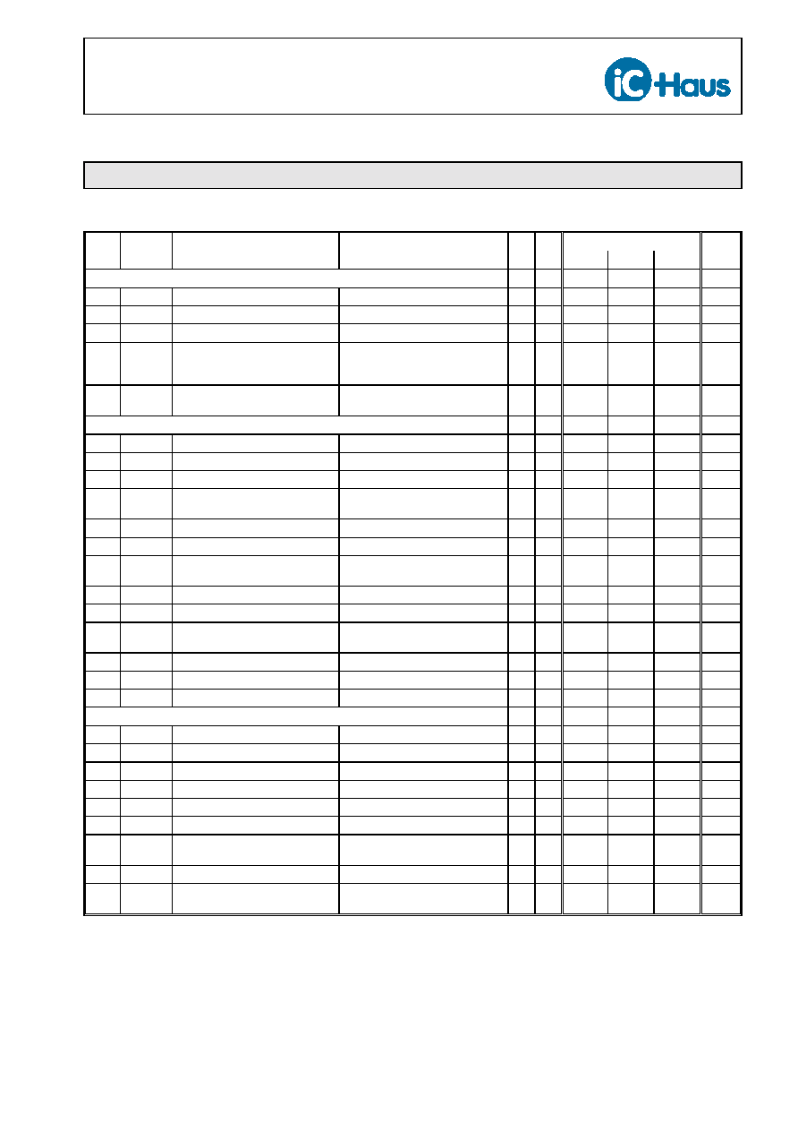
ABSOLUTE MAXIMUM RATINGS
Values beyond which damage may occur; device operation is not guaranteed.
Item Symbol
Parameter
Conditions
Fig.
Unit
Min.
Max.
G001 VCC
Supply Voltage
0
7
V
G002 VB
Driver Supply Voltage
0
32
V
G003 I(A)
Output Current in A1..3
-800
800
mA
G004 I(E)
Input Current in E1..3, INV, TRI, TNER
-4
4
mA
G005 V(NER)
Voltage at NER
32
V
G006 I(NER)
Current in NER
25
mA
E001 Vd()
ESD Susceptibility
at all pins
MIL-STD-883, Method 3015, HBM
100 pF discharged through 1.5 k
2
kV
TG1 Tj
Operating Junction Temperature
-40
165
∞C
TG2 Ts
Storage Temperature Range
-40
150
∞C
THERMAL DATA
Operating Conditions: VB = 4.5..30 V, VCC = 5 V ± 10 %
Item Symbol
Parameter
Conditions
Fig.
Unit
Min.
Typ.
Max.
T1
Ta
Operating Ambient Temperature
Range
(extended range to -40 ∞C on request)
iC-WE SO16W
iC-WE SO20, iC-WE TSSOP20
-25
-25
125
130
∞C
∞C
T2
Rthja
Thermal Resistance SO20
Chip to Ambient
surface mounted with ca. 2 cm
2
heat
sink at leads (see Demo Board)
35
45
K/W
T3
Rthja
Thermal Resistance SO16W
Chip to Ambient
surface mounted with ca. 2 cm
2
heat
sink at leads
55
75
K/W
T4
Rthja
Thermal Resistance TSSOP20
Chip to Ambient
surface mounted, thermal pad
soldered to ca. 2 cm
2
heat sink
30
40
K/W

iC-WE
3-CHANNEL 75 LINE DRIVER
Rev D1, Page 4/10
ELECTRICAL CHARACTERISTICS
Operating Conditions:
VB = 4.5..30 V, VCC = 5 V ± 10 %, Tj = -40..125 ∞C, unless otherwise noted
Item
Symbol
Parameter
Conditions
Tj
Fig.
Unit
∞C
Min.
Typ.
Max.
Total Device
001 VCC
Permissible Supply Voltage
Range
4.5
5.5
V
002 I(VCC)
Supply Current in VCC
-40
27
80
125
8
8
8
8
15
14
13
12
24
23
21
19
mA
mA
mA
mA
003 VB
Permissible Driver Supply Voltage
Range
4.5
30
V
004 I(VB)lo
Supply Current in VB
A1..3 = lo
-40
27
80
125
8
6
5
4
16
14
12
11
24
21
18
15
mA
mA
mA
mA
005 I(VB)hi
Supply Current in VB
A1..3 = hi, I(A1..3) = 0
-40
27
80
125
7
6
4
3
11
9
7
5
14
12
10
8
mA
mA
mA
mA
006 I(VB)Tri
Supply Current in VB,
Outputs Tri-State
TRI = hi,
V(A1..3) = -0.3..VB + 0.3 V
-40
1.2
1.4
mA
mA
Driver Outputs A1..3
101 Vs()lo
Saturation Voltage lo
I(A) = 10 mA
-40
27
80
125
1.15
1.05
1.05
1.0
V
V
V
V
102 Vs()lo
Saturation Voltage lo
I(A) = 30 mA
-40
27
80
125
1.55
1.5
1.5
1.4
V
V
V
V
103 Vs()hi
Saturation Voltage hi
Vs()hi = VB - V(A),
I(A) = -10 mA
-40
27
80
125
1.1
1.0
1.0
0.9
V
V
V
V
104 Vs()hi
Saturation Voltage hi
Vs()hi = VB - V(A),
I(A) = -30 mA
-40
27
80
125
1.45
1.4
1.4
1.3
V
V
V
V
105 Isc()hi
Short-Circuit Current hi
VB = 30 V, V(A) = 0
-800
-500
-300
mA
106 Isc()lo
Short-Circuit Current lo
VB = 30 V, V(A) = VB
300
500
800
mA
107 Rout()
Output Impedance
VB = 30 V, V(A) = 15 V
40
75
100
108 SR()hi
Slew-Rate hi
VB = 30 V, CL = 100 pF
250
V/µs
109 SR()lo
Slew-Rate lo
VB = 30 V, CL = 100 pF
1500
V/µs
110 I0()
Off-State Current
TRI = hi, V(A) = 0..VB
-50
50
µA
111 Vc()hi
Clamp Voltage hi
Vc()hi = V(A) - VB,
TRI = hi, I(A) = 100 mA
0.4
1.5
V
112 Vc()lo
Clamp Voltage lo
TRI = hi, I(A) = -100 mA
-1.5
-0.4
V
Inputs E1..3
201 Vt()hi
Threshold Voltage hi
40
%VCC
202 Vt()lo
Threshold Voltage lo
30
%VCC
203 Vt()hys
Input Hysteresis
Vhys = Vt()hi - Vt()lo
35
110
mV
iC-WE
3-CHANNEL 75 LINE DRIVER
Rev D1, Page 5/10
ELECTRICAL CHARACTERISTICS
Operating Conditions:
VB = 4.5..30 V, VCC = 5 V ± 10 %, Tj = -40..125 ∞C, unless otherwise noted
Item
Symbol
Parameter
Conditions
Tj
Fig.
Unit
∞C
Min.
Typ.
Max.
Inputs E1..3 (continued)
204 Ipu()
Pull-Up Current
V(E) = 0..VCC - 1 V
40
280
µA
205 Vc()hi
Clamp Voltage hi
Vc(E)hi = V(E) - VCC, I(E) = 4 mA
0.4
1.25
V
206 Vc()lo
Clamp Voltage lo
I(E) = -4 mA
-1.25
-0.4
V
207 tp(E-A)
Propagation Delay E
6 A
80
125
200
300
330
330
ns
ns
ns
208 tp()INV Delay Skew E
6 A for
INV = lo vs. INV = hi
25
150
ns
Error Detection
301 VCCon
Turn-on Threshold VCC
4.0
4.49
V
302 VCCoff
Undervoltage Threshold at VCC
decreasing Supply VCC
3.8
4.30
V
303 VCChys Hysteresis
VCChys = VCCon - VCCoff
130
mV
304 VBon
Turn-on Threshold VB
-40
4.0
4.0
4.49
4.6
V
V
305 VBoff
Undervoltage Threshold at VB
decreasing Supply VB
3.8
4.35
V
306 VBhys
Hysteresis
Vbhys = Vbon - VBoff
130
mV
307 VCC
Supply Voltage VCC for NER
Operation
2.6
5.5
V
308 Vs(NER) Saturation Voltage lo at NER
I(NER) = 5 mA
0.7
V
309 Isc(NER) Short-Circuit Current lo in NER
V(NER) = 0..30 V
5
30
mA
310 I0(NER)
Collector Off-State
Current in NER
V(NER) = 0..30 V,
NER = off or VCC < 0.3 V
10
µA
311 Toff
Thermal Shutdown Threshold
150
175
∞C
312 Ton
Thermal Lock-on Threshold
decreasing temperature
125
160
∞C
313 Thys
Thermal Shutdown Hysteresis
Thys = Toff - Ton
20
∞C
Mode Select INV, TRI, TNER
401 Vt()hi
Threshold Voltage hi
40
%VCC
402 Vt()lo
Threshold Voltage lo
30
%VCC
403 Vt()hys
Input Hysteresis
Vt()hys = Vt()hi - Vt()lo
40
90
mV
404 Ipu()
Pull-Up Current
V() = 0..VCC - 0.8 V
35
100
250
µA
405 Vc()hi
Clamp Voltage hi
Vc()hi = V() - VCC, I() = 4 mA
0.4
1.25
V
406 Vc()lo
Clamp Voltage lo
I() = -4 mA
-1.25
-0.4
V
407 tpz
(TRI-A)
Propagation Delay TRI
6 A
(A: lo,hi
6 Tri-State)
RL(A) = 1 k,
RL(VCC,A) = 1 k
5
µs
408 tp(INV-A) Propagation Delay INV
6 A
5
µs
409 tp(TNER-
NER)
Propagation Delay TNER
6 NER
5
µs