 | –≠–ª–µ–∫—Ç—Ä–æ–Ω–Ω—ã–π –∫–æ–º–ø–æ–Ω–µ–Ω—Ç: iC-WK-SO8 | –°–∫–∞—á–∞—Ç—å:  PDF PDF  ZIP ZIP |

iC-WK, iC-WKL
2.4V CW LASER DIODE DRIVER
Rev C2, Page 1/7
SO8
MSOP8
FEATURES
APPLICATIONS
∞
CW operation up to 70mA from 2.4..6V supply voltage and
up to 4A with an external power transistor
∞
Rapid soft start after power-on typical within 70µs
∞
Simple power adjustment via the external resistor
∞
Control loop accuracy better than 1% with changes in
temperature, supply voltage and load current
∞
Integrated reverse polarity protection for the iC and laser
diode
∞
Strong suppression of transients with very small external
capacitors; integrated flyback path
∞
Permanent shutdown with excessive temperature and
overcurrent (i.e. if the laser diode is damaged or the
feedback current path fails)
∞
Two feedback inputs permit all current LD types to be used
(M/P/N configurations)
∞
Modulation via the feedback inputs is possible
∞
Wide monitor current range from 10µA to 2.5mA
∞
Battery-powered LD modules
∞
LD Pointers
∞
Bar-code readers
PACKAGES
BLOCK DIAGRAM
© 2002
iC-Haus GmbH
Tel +49-6135-9292-0
Integrated Circuits
Fax +49-6135-9292-192
Am Kuemmerling 18, D-55294 Bodenheim
http://www.ichaus.com
MD
LD
MD
LD
MD
TRANSIENT
LD
..100nF..
CI
R
..1µF..
CLDA
LD
CVCC
suitable laser diode configurations: N, P, M
MD
NQ
GND
+2.4..+6V
5
1
3
4
2
8
7
200 ..50k
RM
6
PROTECTION
+
-
D
1
0.5V
VREF
...47nF...
CM
47pF
OVER TEMP.
iC-WKL
OVER CURRENT/
FEEDBACK MON.
iC-WK
0..3
RGND
AGND
LDK
MDK
CI
MDA
LDA
GND
VCC
iC-WK, iC-WKL
2.4V CW LASER DIODE DRIVER
Rev C2, Page 2/7
DESCRIPTION
The iC-WK/L device is a driver for laser diodes in continuous wave operation which requires only four external
components. The wide power supply range of 2.4V to 6V and the integrated reverse battery protection allow
for battery operation with a minimum of two cells. A reversed battery connection destroys neither the iC nor
the laser diode.
The iC includes integrated circuitry protecting against destruction by ESD, excessive temperature and over-
current and a soft start which regulates the power and protects the laser diode when the power supply is
switched on. The iC also filters the laser diode power supply for transients.
The power supply is regulated and adapted for the laser diode used by an external resistor at MDA. The
monitor current acts as a reference and is regulated independent of the influence of temperature and supply
voltage (range: 10µA to 2.5mA). The capacitor at CI determines the recovery time constants and start-up time.
A second monitor input, pin MDK, allows the driver to be used for other types of laser diode configuration;
alternatively, it can be used as an analog modulation input (DC to a few kHz).
In the event of failure, such as overcurrent in the laser path with a lack of feedback, for example, a quick
power lockout is activated. The shutdown continues until power is reapplied, permitting a restart. The strain
on power packs and batteries is relieved and the laser class is retained even in the event of a disturbance.
IC-WK offers additional protection by means of spike detection at pin MDA. Should spike or oscillation occur
at pin MDA the power lockout is activated.
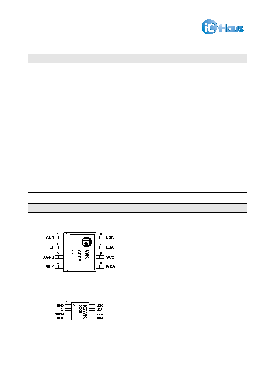
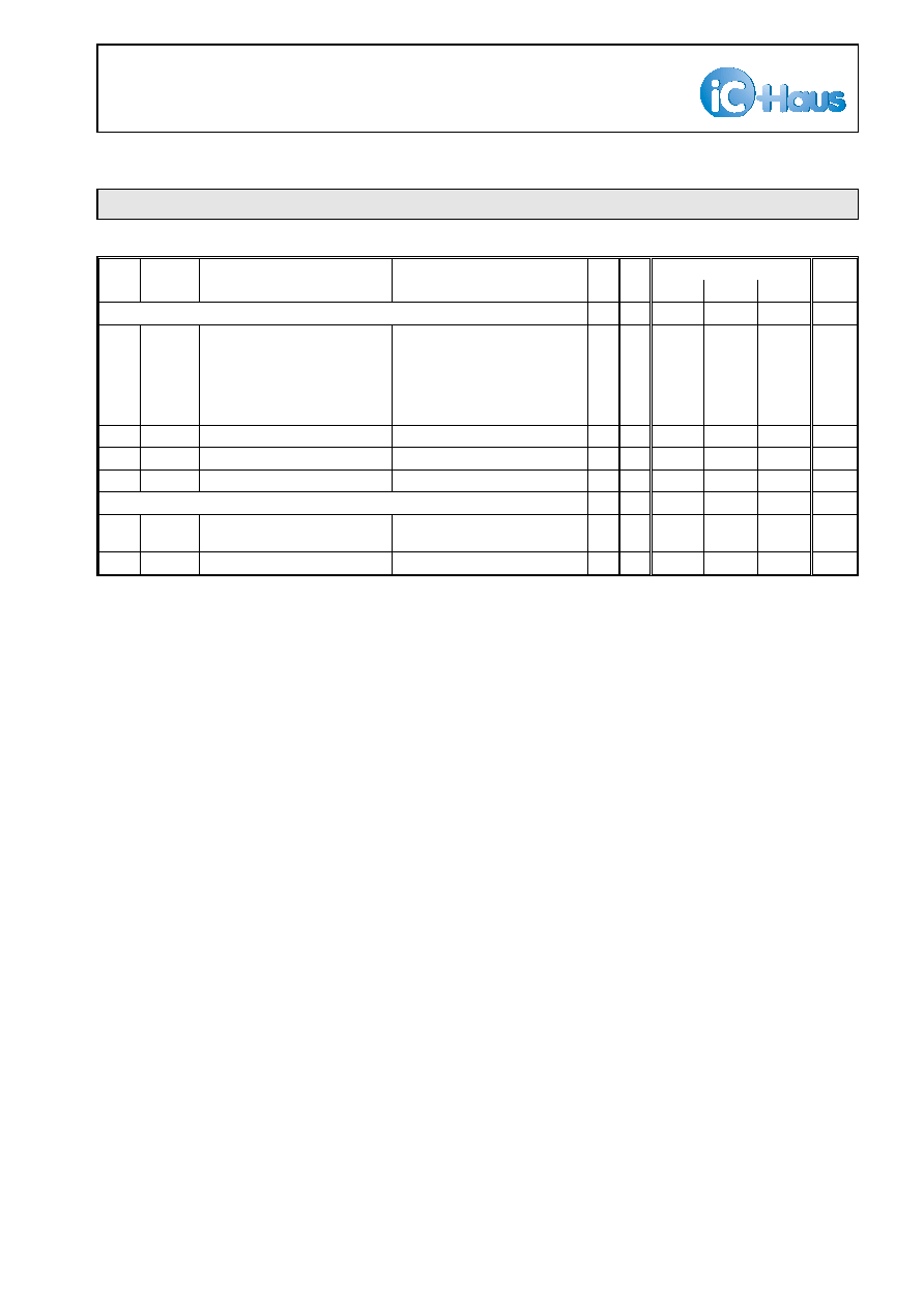
PACKAGES SO8, MSOP8 to JEDEC Standard
PIN CONFIGURATION SO8
PIN FUNCTIONS
(top view)
No. Name Function
1
GND
Ground
2
CI
Capacitance for Power Control
3
AGND Reference Ground for CI, RM
4
MDK
Monitor Input 2
(MD Cathode, modulation)
5
MDA
APC Setup, Monitor Input 1
(MD Anode)
6
VCC
+2.4 .. +6V Supply Voltage
7
LDA
Laser Supply (LD Anode)
8
LDK
Driver Output (LD Cathode)
PIN CONFIGURATION MSOP8 (3mm)

iC-WK, iC-WKL
2.4V CW LASER DIODE DRIVER
Rev C2, Page 3/7
All voltages are referenced to ground unless otherwise noted.
All currents into the device pins are positive; all currents out of the device pins are negative.
ABSOLUTE MAXIMUM RATINGS
Beyond these values damage may occur; device operation is not guaranteed.
Item
Symbol
Parameter
Conditions
Fig.
Unit
Min.
Max.
G001 VCC
Voltage at VCC
-6
6
V
G002 I(VCC)
Current in VCC
-10
95
mA
G003 I(CI)
Current in CI
-10
10
mA
G004 I(LDA)
Current in LDA
-95
10
mA
G005 I(LDK)
Current in LDK
-10
95
mA
G006 I(MDA)
Current in MDA
-10
10
mA
G007 I(MDK)
Current in MDK
-10
10
mA
G008 I(AGMD) Current in AGND
-10
10
mA
G009 I(GND)
Current in GND
-95
10
mA
E001 Vd()
ESD Susceptibility at all pins
MIL-STD-883, Method 3015, HBM
100pF discharged through 1.5k
S
2
kV
TG1 Tj
Operating Junction Temperature
-40
150
∞C
TG2 Tj
Storage Temperature Range
-40
150
∞C
THERMAL DATA
Operating Conditions: VCC= 2.4..6V
Item
Symbol
Parameter
Conditions
Fig.
Unit
Min.
Typ.
Max.
T1
Ta
Operating Ambient Temperature
Range
-40
85
∞C
T2
Rthja
Thermal Resistance Chip/Ambient
SMD assembly,
no additional cooling areas
140
K/W

iC-WK, iC-WKL
2.4V CW LASER DIODE DRIVER
Rev C2, Page 4/7
ELECTRICAL CHARACTERISTICS
Operating Conditions: VCC= 2.4..6V, RM= 200
S
..50k
S
, Tj= -40..125∞C unless otherwise noted
Item
Symbol
Parameter
Conditions
Tj
Fig.
Unit
∞C
Min.
Typ.
Max.
Total Device
001
VCC
Permissible Supply Voltage
2.4
6
V
002
I(LDK)
Permissible Laser Drive Current
(power control range)
Tj= -40..125∞C
Tj= -40..80∞C
5
5
70
90
mA
mA
003
Idc(VCC) Supply Current
without load path
closed control loop, I(MDK)= 0,
RM= 200
S
, I(LDK)= 70mA
2.4
5
mA
004
Ioff(VCC) Supply Current on Reset
2.4
5
mA
005
Ir(VCC)
Reverse Supply Current
RM= 50k
S
-6 -3
mA
006
ton()
Turn-on Delay
VCC: 0V
Ð
5V to 95% I(LDK);
I(LDK)= 60mA, CI= 47nF
I(LDK)= 60mA, CI= 100nF
70
150
µs
µs
007
Vc()hi
Clamp Voltage hi at
VCC, LDA, MDK
I()= 10mA, other pins open
6
9
V
008
Vc()hi
Clamp Voltage hi at LDK
V()< VCC+1V; I()= 10mA,
other pins open
6
9
V
009
Vc()hi
Clamp Voltage hi at MDA
I()= 10mA, other pins open
iC-WKL
iC-WK
6
1.1
9
4
V
V
010
Vc()hi
Clamp Voltage hi at CI
I()= 10mA, other pins open
1.1
4
V
011
Vc()lo
Clamp Voltage lo at
VCC, LDA, MDK, MDA, CI
I()= -10mA, other pins open
-9
V
Reference and Monitor Inputs MDA, MDK, AGND
101
V(MDA)
Reference Voltage at MDA
closed control loop,
V(LDK) >Vs(LDK)
480
500
520
mV
102
dV(MDA) Reference Voltage Temperature
Drift at MDA
see 101;
120
µV/∞C
103
Ierr(MDA) Input Current in MDA
closed control loop,
I(MDK)= 0, I(LDK)= 20..60mA
-300
300
nA
104
dI(MDA)
Input Current Temperature Drift
in MDA
see 103;
-2
2
nA/∞C
105
APCerr
Control Error
RM= 10k
S
, Tj= 0..80∞C
RM= 10k
S
, Tj= -40..125∞C
0.3
1
%
%
106
dI(RM)
Supply Voltage Suppression
V(VCC): 2.4V
Ð
6V,
I(LDK)= 70mA
-1
1
%
107
Rgnd()
Resistor AGND-GND
3
S
301
Vf(MDK)
Voltage at MDK
Vf()= V(LDA) -V(MDK);
I(MDK)= 1µA..1mA
0.46
2
V
302
CR()
Current Ratio I(MDA) / I(MDK)
I(MDK)= 10..500µA
I(MDK)= 500µA..2,5mA
0.98
0.95
1.02
1.05
303
TC()
Current Ratio Temperature
Coefficient I(MDA) / I(MDK)
I(MDK)= 10..500µA
I(MDK)= 500µA..2,5mA
-0.005
-0.025
0.005
0.025
%/∞C
%/∞C
Laser Drive LDA, LDK
201
Vs(LDK)
Saturation Voltage at LDK
I(LDK)= 40mA
I(LDK)= 70mA, Tj= -40..125∞C
I(LDK)= 90mA, Tj= -40..80∞C
300
400
400
mV
mV
202
dI(LD)
Load Balancing Error
I(LD)= 20mA,
I(LDK): 20mA
Ð
70mA
-1
1
%
203
It(LDK)
Overcurrent Threshold in LDK
Tj= -40..125∞C
Tj= -40..80∞C
70
90
130
300
300
mA
mA
iC-WK, iC-WKL
2.4V CW LASER DIODE DRIVER
Rev C2, Page 5/7
ELECTRICAL CHARACTERISTICS
Operating Conditions: VCC= 2.4..6V, RM= 200
S
..50k
S
, Tj= -40..125∞C unless otherwise noted
Item
Symbol
Parameter
Conditions
Tj
Fig.
Unit
∞C
Min.
Typ.
Max.
Laser Drive LDA, LDK (continued)
204
toff()
Overcurrent Reset Delay
lack of feedback:
I(RM)= 0 to I(LDK)= It(LDK);
I(LDK)= 20mA, CI= 47nF
I(LDK)= 20mA, CI= 100nF
I(LDK)= 60mA, CI= 47nF
I(LDK)= 60mA, CI= 100nF
85
170
60
130
µs
µs
µs
µs
205
Vf()
Diode Forward Voltage LDK-LDA I(LDK)< 70mA
1.1
V
206
Rvcc()
Transient Protection Resistor
VCC vs. LDA
4
S
207
Vt(MDA)
Shutdown Threshold at MDA
iC-WK only
0.56
2
V
Control Release Flip-Flop
401
VCCen
Set Threshold for Enable
Flip-Flop
0.6
1.9
V
402
Toff
Overtemperature Shutdown
125
150
∞C