
MDS 2304NZ-1 C
1
Revision 062105
I n t e gra t e d C i r c u i t S y s t e m s
5 2 5 R a c e S t r e e t , S a n J o s e, C A 9 5 1 2 6
t e l ( 4 0 8 ) 2 9 7 - 1 2 0 1
w w w. i c s t . c o m
L
OW
S
KEW
PCI/PCI-X B
UFFER
ICS2304NZ-1
Description
The ICS2304NZ-1 is a high-performance, low skew,
low jitter PCI/PCI-X clock driver. It is designed to
distribute high-speed signals in PCI/PCI-X applications
operating at speeds from 0 to 140 MHz.
The ICS2304NZ-1 is characterized for operation from
-40∞C to +85∞C for automotive and industrial
applications.
Features
∑
Packaged in 8-pin TSSOP (4.4 mm body)
∑
Available in Pb (lead) free package
∑
Frequency range of 0 to 140 MHz
∑
Less than 100 ps skew between outputs
∑
Distribute one clock input to one bank of four outputs
∑
Operating voltage of 3.3 V ±10%
∑
Available in commercial and industrial temperature
ranges
Block Diagram
Logic
Control
OE
CLK_IN
CLK2
CLK1
CLK0
CLK3

L
OW
S
KEW
PCI/PCI-X B
UFFER
MDS 2304NZ-1 C
2
Revision 062105
I n t e gr a t e d C i r c u i t S y s t e m s
5 2 5 R a c e S t r e e t , S a n J o s e, C A 9 5 1 2 6
t e l ( 4 0 8 ) 2 9 7 - 1 2 0 1
w w w. i c s t . c o m
ICS2304NZ-1
Pin Assignment
Functionality Table
Pin Descriptions
C L K _ I N
OE
C L K 0
C L K 2
G N D
V D D
C L K 1
C L K 3
1
2
3
4
8
7
6
5
Inputs
Outputs
CLK_IN
OE
CLK(3:0)
0
0
Tristate
0
1
0
1
0
Tristate
1
1
1
Pin
Number
Pin
Name
Pin
Type
Pin Description
1
CLK_IN
Input
Input reference frequency.
2
OE
Input
Output Enable. When OE is low, it tri-states clock outputs.
3
CLK0
Output
Buffered clock output.
4
GND
Power
Connect to ground.
5
CLK1
Output
Buffered clock output.
6
VDD
Power
Power supply for 3.3 V.
7
CLK2
Output
Buffered clock output.
8
CLK3
Output
Buffered clock output.
L
OW
S
KEW
PCI/PCI-X B
UFFER
MDS 2304NZ-1 C
3
Revision 062105
I n t e gr a t e d C i r c u i t S y s t e m s
5 2 5 R a c e S t r e e t , S a n J o s e, C A 9 5 1 2 6
t e l ( 4 0 8 ) 2 9 7 - 1 2 0 1
w w w. i c s t . c o m
ICS2304NZ-1
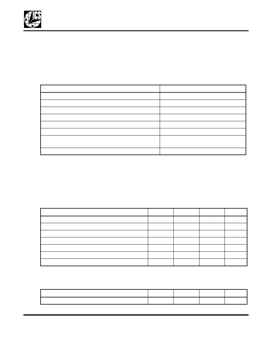
Absolute Maximum Ratings
Stresses above the ratings listed below can cause permanent damage to the ICS2304NZ-1. These ratings,
which are standard values for ICS commercially rated parts, are stress ratings only. Functional operation of
the device at these or any other conditions above those indicated in the operational sections of the
specifications is not implied. Exposure to absolute maximum rating conditions for extended periods can
affect product reliability. Electrical parameters are guaranteed only over the recommended operating
temperature range.
Notes:
1. The input and output negative-voltage ratings may be exceeded if the input and output clamp-current
ratings are observed.
2. This value is limited to 4.6 V maximum.
3. The package thermal impedance is calculated in accordance with JESD 51.
Recommended Operation Conditions
Timing Requirements Over Recommended Ranges of Supply Voltage and Operating
Free-air Temperature
Item
Rating
Supply Voltage Range, V
DD
-0.5 V to 4.3 V
Input Voltage Range, V
I
(see notes 1 and 2)
-0.5 V to V
DD
+ 0.5 V
Output Voltage Range, V
O
(see notes 1 and 2)
-0.5 V to V
DD
+ 0.5 V
Input Clamp Current, I
IK
(V
I
<0 or V
I
>V
DD
)
±50 mA
Output Clamp Current, I
IK
(V
O
<0 or V
O
)
±50 mA
Continuous Total Output Current, I
O
(V
O
= 0 to V
DD
)
±50 mA
Package Thermal Impedance,
JA
(see note 3): PW
Package
230.5
∞C/W
Storage Temperature Range, T
stg
-65
∞C to 150∞C
Parameter
Min.
Typ.
Max.
Units
Supply Voltage, V
DD
3
3.3
3.6
V
High-level Input Voltage, V
IH
0.7 x V
DD
V
Low-level Input Voltage, V
IL
0.3 x V
DD
V
Input Voltage, V
I
0
V
DD
V
High-level Output Current, I
OH
-24
mA
Low-level Output Current, I
OL
24
mA
Operating Free-air Temperature, T
A
-40
≠
+85
∞C
Min.
Typ.
Max.
Units
Clock Frequency, f
CLK
0
140
MHz
L
OW
S
KEW
PCI/PCI-X B
UFFER
MDS 2304NZ-1 C
4
Revision 062105
I n t e gr a t e d C i r c u i t S y s t e m s
5 2 5 R a c e S t r e e t , S a n J o s e, C A 9 5 1 2 6
t e l ( 4 0 8 ) 2 9 7 - 1 2 0 1
w w w. i c s t . c o m
ICS2304NZ-1
Electrical Characteristics at 3.3 V over Recommended Free-air Temperature
Range
VDD = 3.3 V ±10%,
T
A
= -40∞C to +85∞C (unless stated otherwise)
Note 1: Guaranteed by design, not 100% tested in production.
Parameter
Symbol
Conditions
Min.
Typ.
Max.
Units
Input Voltage
V
IK
V
DD
at 3.3 V, I
I
= -18 mA
-1.2
V
High-level Output Voltage
V
OH
V
DD
= min to max,
I
OH
= -1 mA
V
DD
-0.2
3.3
V
V
DD
= 3 V, I
OH
= -24 mA
2
2.3
V
DD
= 3 V, I
OH
= -12 mA
2.4
2.7
Low-level Output Voltage
V
OL
V
DD
= min to max,
I
OH
= 1 mA
0.222
0.2
V
V
DD
= 3 V, I
OL
= 24 mA
0.61
0.8
V
DD
= 3 V, I
OL
= 12 mA
0.31
0.55
High-level Input Current
I
OH
V
DD
= 3 V, V
O
= 1 V
-53
-40
mA
V
DD
= 3.3 V, V
O
= 1.65 V
-54
Low-level Input Current
I
OL
V
DD
= 3 V, V
O
= 2 V
40
53
mA
V
DD
= 3.3 V, V
O
= 1.65 V
57
Input Current
I
I
V = V
DD
or V
O
0.1
50
µA
Dynamic Supply Current
I
DD
Unloaded outputs at
66.67 MHz
13
37
mA
Input Capacitance
(Note 1)
C
I
V
DD
= 3.3 V,
V
I
= 0V or 3.3 V
3
5
pF
Output Capacitance
(Note 1)
C
O
V
DD
= 3.3 V,
V
I
= 0V or 3.3 V
3.2
pF

L
OW
S
KEW
PCI/PCI-X B
UFFER
MDS 2304NZ-1 C
5
Revision 062105
I n t e gr a t e d C i r c u i t S y s t e m s
5 2 5 R a c e S t r e e t , S a n J o s e, C A 9 5 1 2 6
t e l ( 4 0 8 ) 2 9 7 - 1 2 0 1
w w w. i c s t . c o m
ICS2304NZ-1
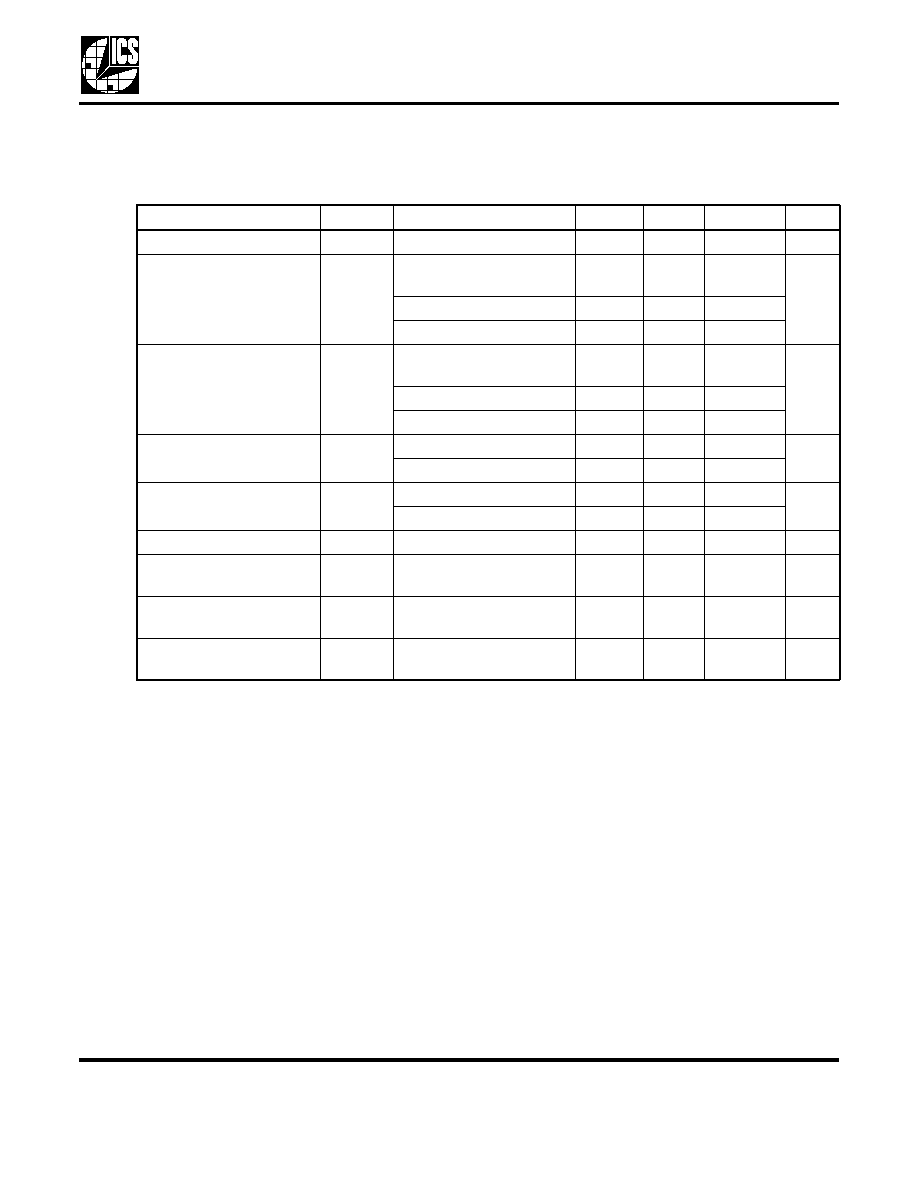
Switching Characteristics at 3.3 V over Recommended Ranges of Supply
Voltage and Operating Free-air Temperature
VDD = 3.3 V ±10%,
T
A
= -40∞C to 85∞C (unless stated otherwise)
Note 1: Guaranteed by design, not 100% tested in production.
Parameter
Symbol
Conditions
Min.
Typ.
Max.
Units
High-to-Low Propagation Delay (Note 1)
t
PLH
V
O
= V
DD
/2
1.8
3.1
3.8
ns
Low-to-High Propagation Delay (Note 1)
t
PHL
V
O
= V
DD
/2
1.8
2.9
3.8
ns
Output Skew Window (Note 1)
T
SK
(o)
V
O
= V
DD
/2
50
100
ps
Pulse Skew = | t
PLH
- t
PHL
| (Note 1)
T
SK
(p)
V
O
= V
DD
/2
300
ps
Process Skew (Note 1)
T
SK
(pr)
V
O
= V
DD
/2
500
ps
CLKIN High Time (Note1)
T
high
66 MHz
6
ns
140 MHz
3
ns
CLKIN Low Time (Note1)
T
low
66 MHz
6
ns
140 MHz
3
ns
Rise Time (Note 1)
T
r
V
OL
=0.8 V,
V
OH
=2.0 V
1.2
2.0
ns
Fall Time (Note 1)
T
f
V
OH
=2.0 V,
V
OL
=0.8 V
1.2
2.0
ns
Cycle-to-Cycle Jitter
T
cyc-cyc
Loaded
outputs
200
ps
Jitter, 1-Sigma
T
j
1s
10,000 cycles
14
40
ps
L
OW
S
KEW
PCI/PCI-X B
UFFER
MDS 2304NZ-1 C
6
Revision 062105
I n t e gr a t e d C i r c u i t S y s t e m s
5 2 5 R a c e S t r e e t , S a n J o s e, C A 9 5 1 2 6
t e l ( 4 0 8 ) 2 9 7 - 1 2 0 1
w w w. i c s t . c o m
ICS2304NZ-1
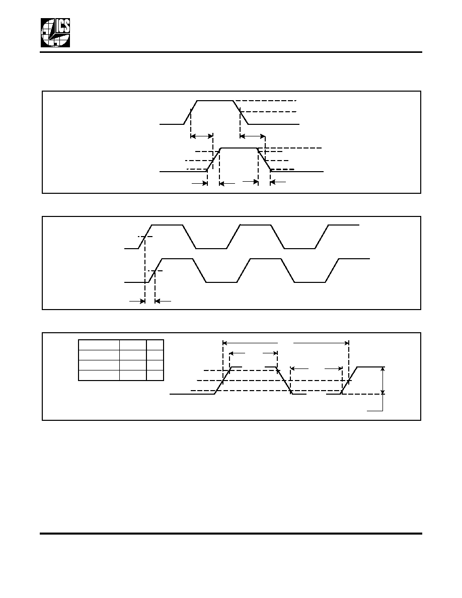
Parameter Measurement Information
Figure 2. Voltage Thresholds for Propagation Delay (t
pd
) Measurements
Figure 3. Output Skew
Figure 4. Clock Waveform
CLK0-CLK3
0.8 V
2.0 V
50% VDD
0.8 V
2.0 V
50% VDD
CLKIN
50% VDD
0V
V
OH
V
OL
t
r
t
f
t
PLH
t
PHL
VDD
50% VDD
Any CLK
t
SK(p)
Any CLK
50% VDD
0.2 V
DD
0.5 V
DD
t
CYC
t
HIGH
t
LOW
V
TEST
V
IH (MIN)
V
IL (MAX)
0.4 V
DD
Peak-to-Peak (minimum)
Parameter
Value
Unit
V
IH (MIN)
V
IL (MAX)
V
TEST
0.5 V
DD
0.4 V
DD
0.35 V
DD
V
V
V
L
OW
S
KEW
PCI/PCI-X B
UFFER
MDS 2304NZ-1 C
7
Revision 062105
I n t e gr a t e d C i r c u i t S y s t e m s
5 2 5 R a c e S t r e e t , S a n J o s e, C A 9 5 1 2 6
t e l ( 4 0 8 ) 2 9 7 - 1 2 0 1
w w w. i c s t . c o m
ICS2304NZ-1
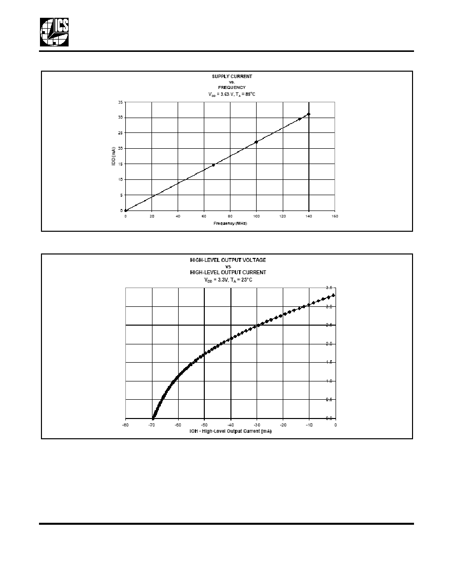
Figure 5. Supply Current vs. Frequency
Figure 6. High-level Output Voltage vs. High-level Output Current
V
O
H - H
i
gh-le
v
e
l Output
V
o
lt
age (V)

L
OW
S
KEW
PCI/PCI-X B
UFFER
MDS 2304NZ-1 C
8
Revision 062105
I n t e gr a t e d C i r c u i t S y s t e m s
5 2 5 R a c e S t r e e t , S a n J o s e, C A 9 5 1 2 6
t e l ( 4 0 8 ) 2 9 7 - 1 2 0 1
w w w. i c s t . c o m
ICS2304NZ-1
Figure 7. Low-level Output Voltage vs. Low-level Output Current
V
O
L - Lo
w-le
v
e
l Output V
o
ltag
e (V)

L
OW
S
KEW
PCI/PCI-X B
UFFER
MDS 2304NZ-1 C
9
Revision 062105
I n t e gr a t e d C i r c u i t S y s t e m s
5 2 5 R a c e S t r e e t , S a n J o s e, C A 9 5 1 2 6
t e l ( 4 0 8 ) 2 9 7 - 1 2 0 1
w w w. i c s t . c o m
ICS2304NZ-1
Marking Diagram
Marking Diagram
(industrial)
Notes:
1. ###### is the lot number.
2. YYWW is the last two digits of the year and week
that the part was assembled.
3. "LF" denotes Pb (lead) free package.
4. Bottom marking: (origin). Origin = country of origin if
not USA.
Marking Diagram
(Pb free)
Marking Diagram
(Pb free/industrial)
BOTTOM
TOP
$$##
####
YYW
W
304N
1
1
4
5
8
BOTTOM
TOP
YYW
W
04N
I
1
1
4
5
8
$$##
####
BOTTOM
TOP
$$##
####
YYW
W
04N
1L
1
4
5
8
BOTTOM
TOP
$$##
####
YYW
W
4N
I
1
L
1
4
5
8
L
OW
S
KEW
PCI/PCI-X B
UFFER
MDS 2304NZ-1 C
10
Revision 062105
I n t e gr a t e d C i r c u i t S y s t e m s
5 2 5 R a c e S t r e e t , S a n J o s e, C A 9 5 1 2 6
t e l ( 4 0 8 ) 2 9 7 - 1 2 0 1
w w w. i c s t . c o m
ICS2304NZ-1
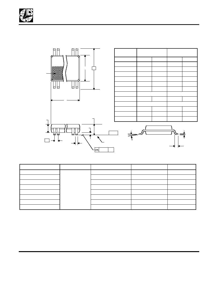
Package Outline and Package Dimensions
(8-pin TSSOP, 4.40 mm Body, 0.65 mm Pitch)
Package dimensions are kept current with JEDEC Publication No. 95, MO-153
Ordering Information
Parts that are ordered with a "LF" suffix to the part number are the Pb-Free configuration and are RoHS compliant.
While the information presented herein has been checked for both accuracy and reliability, Integrated Circuit Systems (ICS)
assumes no responsibility for either its use or for the infringement of any patents or other rights of third parties, which would
result from its use. No other circuits, patents, or licenses are implied. This product is intended for use in normal commercial
applications. Any other applications such as those requiring extended temperature range, high reliability, or other extraordinary
environmental requirements are not recommended without additional processing by ICS. ICS reserves the right to change any
circuitry or specifications without notice. ICS does not authorize or warrant any ICS product for use in life support devices or
critical medical instruments.
Part / Order Number
Marking
Shipping Packaging
Package
Temperature
ICS2304NZG-1
see page 8
Tubes
8-pin TSSOP
0 to +70
∞ C
ICS2304NZG-1T
Tape and Reel
8-pin TSSOP
0 to +70
∞ C
ICS2304NZG-1LF
Tubes
8-pin TSSOP
0 to +70
∞ C
ICS2304NZG-1LFT
Tape and Reel
8-pin TSSOP
0 to +70
∞ C
ICS2304NZGI-1
Tubes
8-pin TSSOP
-40 to +85
∞ C
ICS2304NZGI-1T
Tape and Reel
8-pin TSSOP
-40 to +85
∞ C
ICS2304NZGI-1LF
Tubes
8-pin TSSOP
-40 to +85
∞ C
ICS2304NZGI-1LFT
Tape and Reel
8-pin TSSOP
-40 to +85
∞ C
INDEX
AREA
1 2
8
D
E1
E
SEATING
PLANE
A1
A
A2
e
- C -
b
aaa
C
c
L
Millimeters
Inches
Symbol
Min
Max
Min
Max
A
--
1.20
--
0.047
A1
0.05
0.15
0.002
0.006
A2
0.80
1.05
0.032
0.041
b
0.19
0.30
0.007
0.012
C
0.09
0.20
0.0035
0.008
D
2.90
3.10
0.114
0.122
E
6.40 BASIC
0.252 BASIC
E1
4.30
4.50
0.169
0.177
e
0.65 Basic
0.0256 Basic
L
0.45
0.75
0.018
0.030
0
∞
8
∞
0
∞
8
∞
aaa
--
0.10
--
0.004