
Integrated
Circuit
Systems, Inc.
User-Programmable Dual High-Performance Clock Generator
ICS2595
Pin Configuration
Block Diagram
ICS2595 RevB 3/2/00
20-Pin DIP or SOIC
Features
∑
Advanced ICS monolithic phase-locked loop
technology for extremely low jitter
∑
Supports high-resolution graphics - VCLK
output to 145 MHz
∑
Completely integrated - requires only external
crystal (or reference frequency and decoupling)
∑
Power-down modes support portable computing
∑
Sixteen selectable VCLK frequencies
(all user re-programmable)
∑
Four selectable MCLK frequencies
(all user re-programmable)
Description
The ICS2595 is a dual-PLL (phase-locked loop) clock
generator specifically designed for high-resolution, high-
refresh rate, video applications. The video PLL generates
any of 16 pre-programmed frequencies through selection
of the address lines FS0-FS3. Similarly, the auxiliary PLL
can generate any one of four pre-programmed frequencies
via the MS0 & MS1 lines.
A unique feature of the ICS2595 is the ability to redefine
frequency selections in both the VCLK and MCLK synthesiz-
ers after power-up. This permits complete set-up of the
frequency table upon system initialization.
Applications
∑
PC Graphics
∑
VGA/Supper VGA/XGA Applications
Not recommended for new designs

2
ICS2595
Pin Descriptions
R
E
B
M
U
N
N
I
P
E
M
A
N
N
I
P
E
P
Y
T
N
O
I
T
P
I
R
C
S
E
D
1
1
X
N
I
t
u
p
n
I
y
c
n
e
u
q
e
r
F
e
c
n
e
r
e
f
e
R
/
1
n
o
i
t
c
e
n
n
o
c
l
a
t
s
y
r
c
z
t
r
a
u
Q
2
2
X
T
U
O
2
n
o
i
t
c
e
n
n
o
c
l
a
t
s
y
r
c
z
t
r
a
u
Q
3
Q
E
R
F
T
X
E
N
I
t
u
p
n
I
y
c
n
e
u
q
e
r
F
l
a
n
r
e
t
x
E
4
0
S
F
N
I
B
S
L
t
c
e
l
e
S
y
c
n
e
u
q
e
r
F
L
L
P
K
L
C
V
5
1
S
F
N
I
t
i
B
t
c
e
l
e
S
y
c
n
e
u
q
e
r
F
L
L
P
K
L
C
V
6
E
B
O
R
T
S
N
I
)
3
S
F
-
0
S
F
(
s
t
i
t
c
e
l
e
S
K
L
C
V
f
o
h
c
t
a
L
r
o
f
l
o
r
t
n
o
C
7
2
S
F
N
I
t
i
B
t
c
e
l
e
S
y
c
n
e
u
q
e
r
F
L
L
P
K
L
C
V
8
3
S
F
N
I
B
S
M
t
c
e
l
e
S
y
c
n
e
u
q
e
r
F
L
L
P
K
L
C
V
9
0
S
M
N
I
B
S
L
t
c
e
l
e
S
y
c
n
e
u
q
e
r
F
L
L
P
K
L
C
M
6
1
,
4
1
,
0
1
D
N
G
R
W
P
d
e
t
c
e
n
n
o
c
e
b
t
s
u
m
s
n
i
p
l
l
A
.
d
n
u
o
r
G
e
c
i
v
e
D
1
1
1
S
M
N
I
B
S
M
t
c
e
l
e
S
y
c
n
e
u
q
e
r
F
L
L
P
K
L
C
M
2
1
K
L
C
M
T
U
O
t
u
p
t
u
O
y
c
n
e
u
q
e
r
F
K
L
C
M
0
2
,
3
1
D
D
V
R
W
P
d
e
t
c
e
n
n
o
c
e
b
t
s
u
m
s
n
i
p
l
l
A
.
D
D
V
e
g
a
t
S
t
u
p
t
u
O
5
1
A
A
V
R
W
P
D
D
V
r
e
z
i
s
e
h
t
n
y
S
7
1
D
E
V
R
E
S
E
R
C
/
N
D
N
G
o
t
d
e
t
c
e
n
n
o
c
e
b
t
s
u
M
8
1
K
L
C
F
E
R
T
U
O
t
u
p
t
u
O
k
c
o
l
C
d
e
c
n
e
r
e
f
e
R
d
e
r
e
f
f
u
B
9
1
K
L
C
V
T
U
O
t
u
p
t
u
O
y
c
n
e
u
q
e
r
F
K
L
C
V

ICS2595
3
Digital Inputs
The FS0-FS3 pins and the STROBE pin are used to select
the desired operating frequency of the VCLK output from
the 16 pre-programmed/user-programmed selections in
the ICS2595. These pins are also used to load new frequency
data into the registers.
The standard interface for the ICS2595 matches the interface
of the industry standard ICS2494. That is, the FS0-FS3
inputs access the device internals transparently when the
STROBE pin is high.
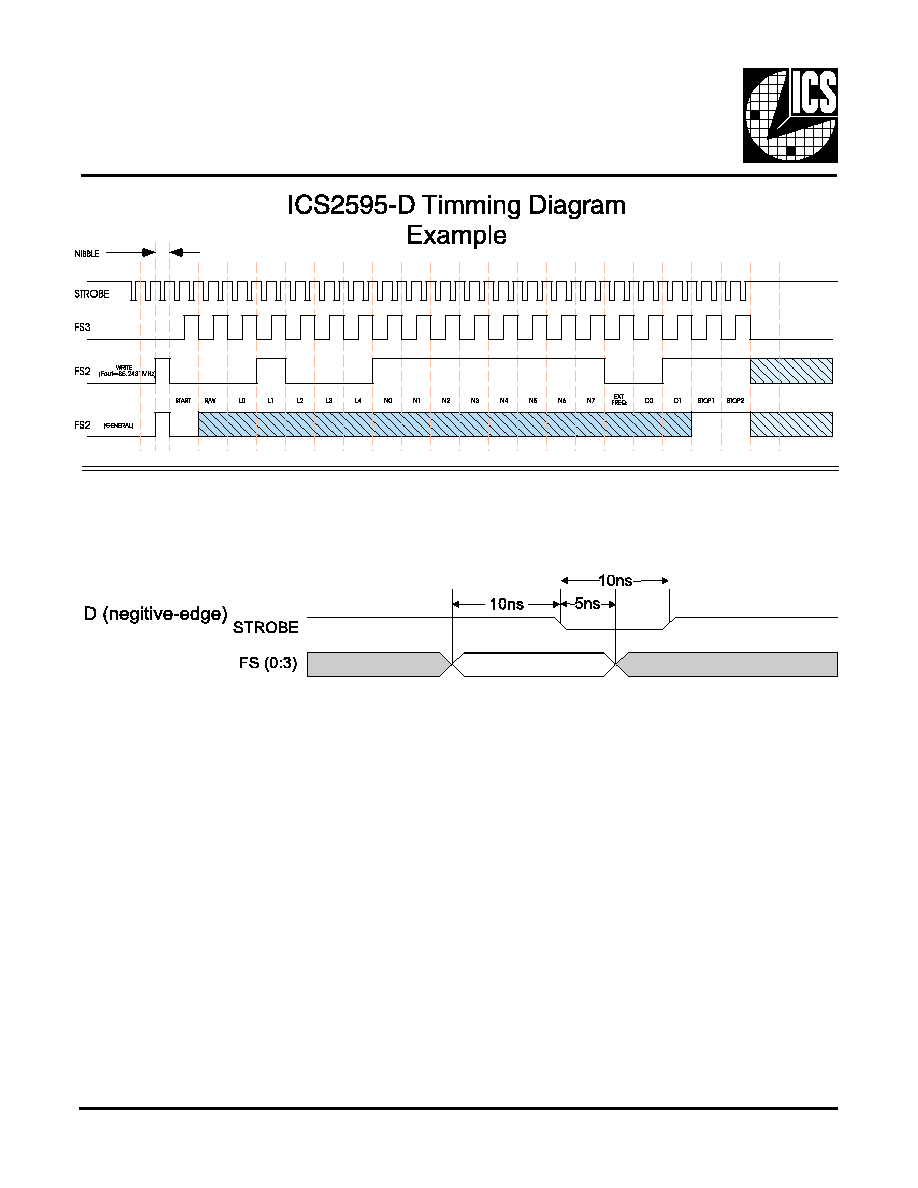
The digital interface for the ICS2595 (i.e. the FS0-FS3
inputs) may be optionally configured for edge-triggered
or level-activated operation of the STROBE pin. Example
timing requirements for each of the four options are
shown in Figure 1.
The programming sequence has been designed in such a
way that STROBE pin need not be used (as in situations
where the device is connected to the frequency select port
of some VGA chips).
VCLK Output Frequency Selection
To change the VCLK output frequency, simply write the
appropriate data to the ICS2595 FS inputs. The synthesizer
will output the new frequency programmed into that location
after a brief delay (see time-out specifications).
Upon device power-up, the selected frequency will be the
frequency pre-programmed into address 0 until a device
write is performed.
MCLK Output Frequency Selection
The MS0-MS1 pins are used to directly select the desired
operating frequency of the MCLK output from the four
pre-programmed/user-programmed selections in the
ICS2595. These inputs are not latched, nor are they involved
with memory programming operations.
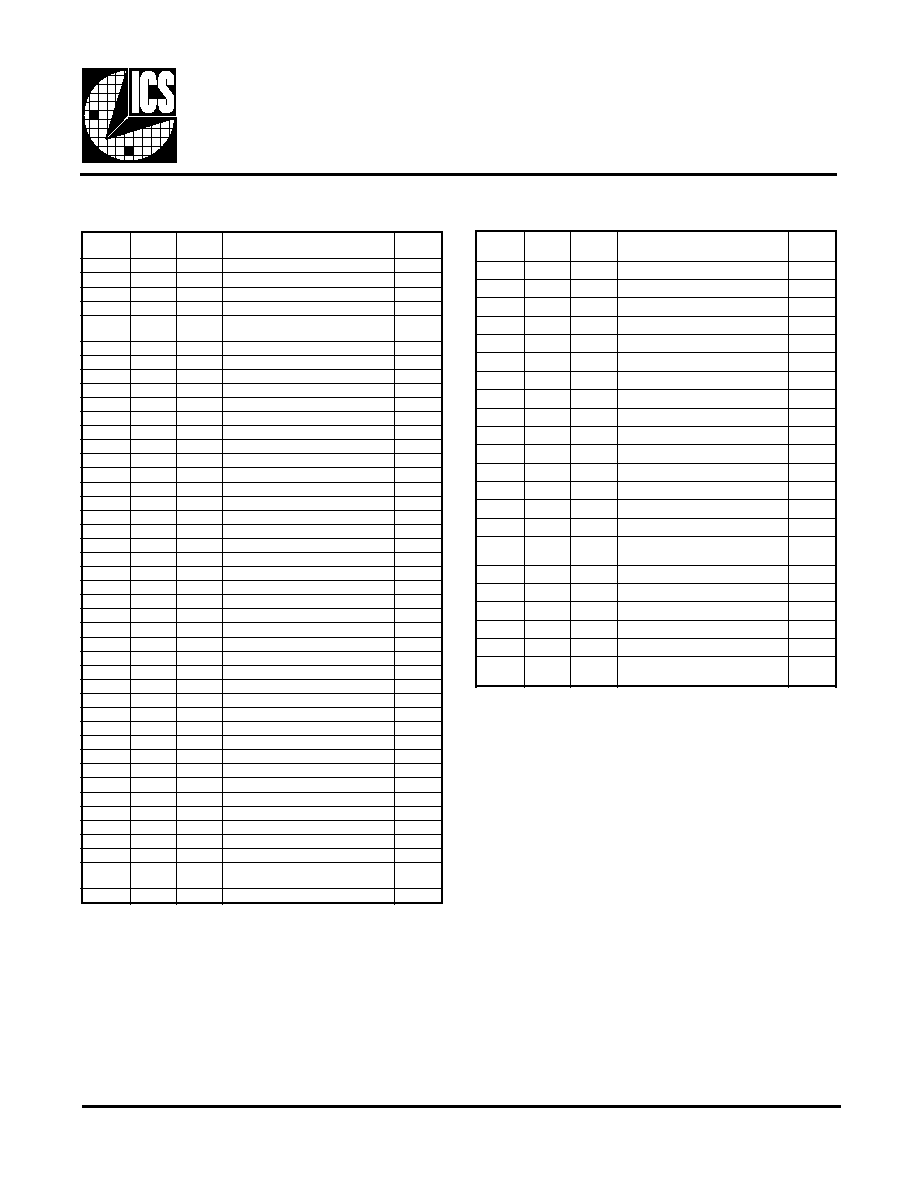
Programming Mode Selection
In order to ensure that reliable programming under all
circumstances, we require that two "nibble" writes be
added to the beginning of the programming sequence that
was previously specified. The new sequence is shown in
Table 1. Note that the FS3 data is "0" for these first two
writes.
e
l
b
b
i
N
0
S
F
1
S
F
2
S
F
3
S
F
1
X
X
0
0
2
X
X
1
0
3
X
X
)
"
0
"
e
b
t
s
u
m
(
ti
b
T
R
A
T
S
0
4
X
X
"
1
5
X
X
e
b
t
s
u
m
(
ti
b
l
o
r
t
n
o
c
*
W
/
R
)
"
0
"
0
6
X
X
"
1
7
X
X
)
B
S
L
n
o
it
a
c
o
l
(
O
L
0
8
X
X
"
1
9
X
X
1
L
0
0
1
X
X
"
1
1
1
X
X
2
L
0
2
1
X
X
"
1
3
1
X
X
3
L
0
4
1
X
X
"
1
5
1
X
X
)
B
S
M
n
o
it
a
c
o
l
(
4
L
0
6
1
X
X
"
1
7
1
X
X
B
S
L
k
c
a
b
d
e
e
f
(
0
N
0
8
1
X
X
"
1
9
1
X
X
1
N
0
0
2
X
X
"
1
1
2
X
X
2
N
0
2
2
X
X
"
1
3
2
X
X
3
N
0
4
2
X
X
"
1
5
2
X
X
4
N
0
6
2
X
X
"
1
7
2
X
X
5
N
0
8
2
X
X
"
1
9
2
X
X
6
N
0
0
3
X
X
"
1
1
3
X
X
)
B
S
M
k
c
a
b
d
e
e
f
(
7
N
0
2
3
X
X
"
1
3
3
X
X
)
"
1
"
fi
t
c
e
l
e
s
(
Q
E
R
F
T
X
E
0
4
3
X
X
"
1
5
3
X
X
)
B
S
M
r
e
d
v
i
d
-
t
s
o
p
(
0
D
0
6
3
X
X
"
1
7
3
X
X
)
B
S
M
r
e
d
v
i
d
-
t
s
o
p
(
1
D
0
8
3
X
X
"
1
9
3
X
X
)
"
1
"
e
b
t
s
u
m
(
ti
b
1
P
O
T
S
0
0
4
X
X
"
1
1
4
X
X
)
"
1
'
e
b
t
s
u
m
(
ti
b
2
P
O
T
S
0
2
4
X
X
"
1
Table 1: Programming Sequence
Because the same pins are used for both VCLK frequency
selection and re-programming the device frequency table,
a specific procedure must be observed for selection between
these modes. Device programming is accomplished by
executing a "programming sequence". The latched FS2
input functions as a data input, and the latched FS3 input
functions as a data clock when this mode is activated. As
the latched FS3 data transitions from 0 to 1, the latched
FS2 data is shifted into the register. Note that it is the

4
ICS2595
LATCHED FS inputs, not the FS inputs themselves, that
are interpreted by the internal logic. Interface logic resides
between the FS input pins and the programming/frequency
select logic. The appropriate "data write" procedure must
be observed. See the section "Digital Interface" in this
supplement for more information.
These rules must be followed:
∑
Calculate
T
max and
T
min in seconds (where R is the
modulus of the reference divider and
F
ref is the
reference frequency in Hz) by the following formulas:
∑
A programming sequence consists of 42 successive
data writes to the device as shown in table 1: no delay
greater than
T
max or less than
T
min may occur between
any two successive writes.
∑
A readback sequence consists of 64 successive data
writes to the device as shown in table 2: no delay
greater than
T
max or less than
T
min may occur between
any two successive writes.
∑
Programming or readback sequences must be preceded
by a "quiet" period of at least 2*
T
max with no data
writes to the device unless it was immediately preceded
by another legal programming (or readback) sequence
(nothing else in between)
∑
To change the active VCLK frequency selection, simply
write that data to the device; the last data written to the
part will always become VCLK frequency select after
a delay of approximately 2*
T
max. The internal shift
register is cleared at this time also.
The FS0 & FS1 inputs are not used for programming, so it
is possible to use a two-pin interface for programming and
frequency selection (any bank of four VCLK addresses).
The reference frequency source must be operational for
proper execution of the programming sequence. If the on-
chip crystal oscillator is, allow at least 4*
T
max after the
device has valid power before attempting to program it.
Data Description
Location Bits (l0-L4)
The first five bits after the start bit control the frequency
location to be re-programmed according to this table. The
rightmost bit (the LSB) of the five shown in each
selection of the table is the first one sent.
)
0
.
4
(
L
N
O
I
T
A
C
O
L
0
0
0
0
0
0
s
s
e
r
d
d
A
K
L
C
V
1
0
0
0
0
1
s
s
e
r
d
d
A
K
L
C
V
0
1
0
0
0
2
s
s
e
r
d
d
A
K
L
C
V
1
1
0
0
0
3
s
s
e
r
d
d
A
K
L
C
V
0
0
1
0
0
4
s
s
e
r
d
d
A
K
L
C
V
1
0
1
0
0
5
s
s
e
r
d
d
A
K
L
C
V
0
1
1
0
0
6
s
s
e
r
d
d
A
K
L
C
V
1
1
1
0
0
7
s
s
e
r
d
d
A
K
L
C
V
0
0
0
1
0
8
s
s
e
r
d
d
A
K
L
C
V
1
0
0
1
0
9
s
s
e
r
d
d
A
K
L
C
V
0
1
0
1
0
0
1
s
s
e
r
d
d
A
K
L
C
V
1
1
0
1
0
1
1
s
s
e
r
d
d
A
K
L
C
V
0
0
1
1
0
2
1
s
s
e
r
d
d
A
K
L
C
V
1
0
1
1
0
3
1
s
s
e
r
d
d
A
K
L
C
V
0
1
1
1
0
4
1
s
s
e
r
d
d
A
K
L
C
V
1
1
1
1
0
5
1
s
s
e
r
d
d
A
K
L
C
V
0
0
0
0
1
0
s
s
e
r
d
d
A
K
L
C
M
1
0
0
0
1
1
s
s
e
r
d
d
A
K
L
C
M
0
1
0
0
1
2
s
s
e
r
d
d
A
K
L
C
M
1
1
0
0
1
4
s
s
e
r
d
d
A
K
L
C
M
Table 3 - Location Bit Programming
Feedback Set Bits (N0-N7)
These bits control the feedback divider setting for the
location specified. The modulus of the feedback divider
will be equal to the value of these bits + 257. The least
significant bit (N0) is sent first.
Post-Divider Set Bits (D0-D1)
These bits control the post-divider setting for the location
specified according to this table. The least significant bit
(D0) is sent first.
Table 4 - Post-Divider Programming
)
0
-
1
(
D
R
E
D
I
V
I
D
-
T
S
O
P
0
0
8
1
0
4
0
1
2
1
1
1
T
min =
6* R
F
ref
T
max =
4096* R
F
ref

ICS2595
5
Read/Write* Control Bit
When set to a "0," the ICS2595 shift register will transfer its
contents to the selected memory register at the completion
of the programming sequence.
When this bit is a "1," the selected memory location will be
transferred to the shift register to permit a subsequent readback
of data. No modification of device memory will be performed.
"Readback" of a location in the frequency table may be
performed by execution the 64 step readback sequence. The
readback sequence is shown in Table 2. Note that the readback
sequence is essentially the programming sequence (with the
R/W* bit set high) followed by the actual data readback.
The bi-directional FS0 pin will convert to output mode after
the 42nd nibble write and the logic level output will be that
of the first data bit (N0). Subsequent "clocking" by latching
FS3 to "0" and then to "1" will shift out the remaining data
bits. The last two writes will return the FS0 pin to input
mode.
EXTFREQ Input
The EXTFREQ input allows an externally generated fre-
quency to be routed to the VCLK or MCLK output pins
under device programming control. If the EXTFREQ bit is
set (logic "1") at the selected address location, the frequency
applied to the EXTFREQ input will be routed to the output
instead of the frequency generated by the VCLK (or MCLK)
PLL.
When setting the EXTFREQ bit to a "1," be sure that the D0
and D1 bits are not both set to "1" also, unless it is intended
that the phase-locked loop be shutdown as well.
Power Conservation
The ICS2595 supports power conservation by permitting
either or both of the phase-locked loops to be disabled. This
can be done by programming a particular address to have
EXTFREQ, D0, & D1 bits set to a logic "1." Any frequency
applied to the EXTFREQ pin will still be passed through the
output multiplexer and appear at the respective output.The
crystal oscillator is not affected by this power-down function
and will continue to operate normally.
Frequency Synthesizer Description
Refer to the block diagram of the ICS2595. The ICS2595
generates its output frequencies using phase-locked loop
techniques. The phase-locked loop (or PLL) is a closed-loop
feedback system that drives the output frequency to be
ratiometrically related to the reference frequency pro-vided
to the PLL. The phase-frequency detector shown in the
block diagram drives the VCO to a frequency that will cause
the two inputs to the phase-frequency detector to be matched
in frequency and phase. This occurs when:
where N is the effective modulus of the feedback divider
chain and R is the modulus of the reference divider chain.
The feedback divider on the ICS2595 may be set to any
integer value from 257 to 512. This is done by the setting of
the N0-N7 bits. The standard reference divider on the ICS2595
is fixed to a value of 43 (this may be set to a different value
via ROM programming; contact factory). The ICS2595 is
equipped with a post-divider and multiplexer that allows
the output frequency range to be scaled down from that of
the VCO by a factor of 2, 4, or 8,
therefore, the VCO frequency range will be from 5.976 to
11.906 (257/43 to 512/43) of the reference frequency. The
output frequency range will be from 0.747 to 11.906 times
the reference frequency. Worst case accuracy for any desired
fre-quency within that range will be 0.2%.
If a 14.31818 MHz reference is used, the output frequency
range would be from 10.697 MHz to 170.486 MHz (but the
upper end is first limited to 145 MHz by the ICS2595 output
driver).
Programming Example
Suppose that we want differential CLK output to be 45.723
MHz. We will assume the reference frequency to be 14.31818
MHz.
The VCO frequency range will be 85.565 MHz to 170.486
MHz (5.976 * 14.31818 to 11.906 * 14.31818). We will
need to set the post-divider to two to get an output of 45.723
MHz.
The VCO will then need to be programmed to two times
45.723 MHz, or 91.446 MHz. To calculate the required feed-
F
VCO =
F
XTAL1*
N
R

6
ICS2595
back divider modulus we divide the VCO frequency by the
reference frequency and multiply by the reference divider:
which we round off to 275. The exact output frequency will
be:
The value of the N programming bits may be calculated by
subtracting 257 from the desired feedback divider modulus.
Thus, the N value will be set to 18 (275-257) or 000100102.
The D bit programming is set to 10 (from Table 4).
Reference Oscillator & Crystal
Selection
The ICS2595 has on-board circuitry to implement a Pierce
oscillator with the addition of only one external component,
a quartz crystal. Pierce oscillators operate the crystal in
parallel-resonant (also called anti-resonant mode). See the
AC Characteristics for the effective capacitive loading to
specify when ordering crystals.
Crystals characterized for their series-resonant frequency
may also be used with the ICS2595. Be aware that the
oscillation frequency in circuit will be slightly higher than
the frequency that is stamped on the can (typically 0.025-
0.05%).
As the entire operation of the phaselocked loop depends on
having a stable reference frequency, we recommend that the
crystal be mounted as closely as possible to the package.
Avoid routing digital signals or the ICS2595 outputs
underneath or near these traces. It is also desirable to ground
the crystal can to the ground plane, if possible.
External Reference Sources
An external frequency source may be used as the reference
for the VCLK and MCLK PLLs. To implement this, simply
connect the reference frequency source to the X1 pin of the
ICS2595. For best results, insure that the clock edges are as
clean and fast as possible and that the input voltage thresholds
are not violated.
91.446
14.31818
*43=274.62
275
43
*14.31818*
1
2
=45.784 MHz
Power Supply
The ICS2595 has three GND pins to reduce the effects of
package inductance. All pins are connected to the same
potential on the die (the ground bus). All of these pins
should connect to the ground plane of the video board as
close to the package as is possible.
The ICS2595 has two VDD pins which supply of +5 volt
power to the output stages. These pins should be connected
to the power plane (or bus) using standard high-frequency
decoupling practice. That is, use low-capacitors should have
low series inductance and be mounted close to the ICS2595.
The VAA pin is the power supply for the synthesizer
circuitry and other lower current digital functions. We
recommend that RC decoupling or zener regulation be
provided for this pin. This will allow the PLL to track
through power supply fluctuations without visible effects.
ICS2595
7
Absolute Maximum Ratings
DC Characteristics
Supply Voltage ............................................................................................... -5V to +7 V
Logic inputs ........................................................................................... 5V to VDD +.5V
Ambient operating temp ................................................................................. 0∞ to 70∞C
Storage temperature ............................................................................. -85∞C to +150∞C
Stresses above those listed under Absolute Maximum Ratings may cause permanent damage to the device. These ratings
are stress specifications only and functional operation of the device at these or any other conditions above those listed
in the operational sections of the specifications is not implied. Exposure to absolute maximum rating conditions for
extended periods may affect product reliability.
s
c
i
t
s
i
r
e
t
c
a
r
a
h
C
C
D
R
E
T
E
M
A
R
A
P
L
O
B
M
Y
S
S
N
O
I
T
I
D
N
O
C
T
S
E
T
N
I
M
P
Y
T
X
A
M
S
T
I
N
U
s
t
u
p
n
I
e
l
b
i
t
a
p
m
o
C
-
L
T
T
-
-
-
-
:
)
E
B
O
R
T
S
,
1
-
0
S
M
,
3
-
0
S
V
(
-
-
-
-
e
g
a
t
l
o
V
h
g
i
H
t
u
p
n
I
h
i
V
0
.
2
-
5
.
0
=
D
D
V
V
e
g
a
t
l
o
V
w
o
L
t
u
p
n
I
l
i
V
5
.
0
-
S
S
V
-
8
.
0
V
t
n
e
r
r
u
C
h
g
i
H
t
u
p
n
I
h
i
I
-
-
0
1
A
µ
t
n
e
r
r
u
C
w
o
L
t
u
p
n
I
l
i
I
-
-
0
0
2
A
µ
e
c
n
a
t
i
c
a
p
a
c
t
u
p
n
I
n
i
C
-
-
8
F
p
:
1
L
A
T
X
-
-
-
-
e
g
a
t
l
o
V
h
g
i
H
t
u
p
n
I
h
x
V
5
7
.
0
*
D
D
V
-
5
.
0
+
D
D
V
V
e
g
a
t
l
o
V
w
o
L
t
u
p
n
I
1
x
V
5
.
0
-
S
S
V
-
5
2
.
0
*
D
D
V
V
:
s
t
u
p
t
u
O
K
L
C
M
,
K
L
C
V
-
-
-
-
e
g
a
t
l
o
V
h
g
i
H
t
u
p
t
u
O
h
o
V
4
.
2
-
-
V
A
m
4
.
0
=
h
o
I
@
-
-
-
-
e
g
a
t
l
o
V
w
o
L
t
u
p
t
u
O
l
o
V
-
-
4
.
0
V
A
m
0
.
8
=
l
o
I
@
-
-
-
-

8
ICS2595
AC Characteristics
s
c
i
t
s
i
r
e
t
c
a
r
a
h
C
C
A
R
E
T
E
M
A
R
A
P
L
O
B
M
Y
S
S
N
O
I
T
I
D
N
O
C
T
S
E
T
N
I
M
P
Y
T
X
A
M
S
T
I
N
U
:
p
o
o
L
d
e
k
c
o
L
-
e
s
a
h
P
-
-
-
-
O
C
V
K
L
C
M
,
K
L
C
V
y
c
n
e
u
q
e
r
F
o
c
v
F
0
6
-
5
8
1
z
H
M
e
m
i
T
e
r
i
u
q
c
A
L
L
P
k
c
o
l
T
-
0
0
5
-
c
e
S
µ
r
o
t
a
l
l
i
c
s
O
l
a
t
s
y
r
C
-
-
-
-
e
g
n
a
R
y
c
n
e
u
q
e
r
F
l
a
t
s
y
r
C
l
a
t
x
F
5
-
5
2
z
H
M
g
n
i
d
a
o
L
l
e
l
l
a
r
a
P
e
c
n
a
t
i
c
a
p
a
C
-
0
2
-
F
p
e
m
i
T
h
g
i
H
m
u
m
i
n
i
M
1
L
A
T
X
i
h
x
T
8
-
-
s
n
e
m
i
T
w
o
L
m
u
m
i
n
i
M
1
L
A
T
X
o
l
x
T
8
-
-
s
n
:
s
e
i
l
p
p
u
S
r
e
w
o
P
-
-
-
-
t
n
e
r
r
u
C
y
l
p
p
u
S
D
D
V
d
d
i
-
-
5
3
A
m
t
n
e
r
r
u
C
y
l
p
p
u
S
A
A
V
a
a
I
-
-
0
1
A
m
:
s
t
u
l
p
t
u
O
l
a
t
i
g
i
D
-
-
-
-
T
U
O
L
A
T
X
,
K
L
C
M
,
K
L
C
V
F
p
0
2
=
d
a
o
l
C
@
e
m
i
T
e
s
i
R
r
T
-
-
2
s
n
T
U
O
L
A
T
S
,
K
L
C
M
,
K
L
C
V
F
p
0
2
=
d
a
o
l
C
@
e
m
i
T
l
l
a
F
f
T
-
-
2
s
n
ICS2595
9
Table 2: Readback Sequence
-
b
b
i
N
e
l
0
S
F
1
S
F
2
S
F
3
S
F
1
X
X
0
0
2
X
X
1
0
3
X
X
)
"
0
"
e
b
t
s
u
m
(
t
i
b
T
R
A
T
S
0
4
X
X
"
1
5
X
X
e
b
t
s
u
m
(
t
i
b
l
o
r
t
n
o
c
*
W
/
R
)
"
0
"
0
6
X
X
"
1
7
X
X
)
B
S
L
n
o
i
t
a
c
o
l
(
O
L
0
8
X
X
"
1
9
X
X
1
L
0
0
1
X
X
"
1
1
1
X
X
2
L
0
2
1
X
X
"
1
3
1
X
X
3
L
0
4
1
X
X
"
1
5
1
X
X
)
B
S
M
n
o
i
t
a
c
o
l
(
4
L
0
6
1
X
X
"
1
7
1
X
X
X
0
8
1
X
X
X
1
9
1
X
X
X
0
0
2
X
X
X
1
1
2
X
X
X
0
2
2
X
X
X
1
3
2
X
X
X
0
4
2
X
X
X
1
5
2
X
X
X
0
6
2
X
X
X
1
7
2
X
X
X
0
8
2
X
X
X
1
9
2
X
X
X
0
0
3
X
X
X
1
1
3
X
X
X
0
2
3
X
X
X
1
3
3
X
X
X
0
4
3
X
X
X
1
5
3
X
X
X
0
6
3
X
X
X
1
7
3
X
X
X
0
8
3
X
X
X
1
9
3
X
X
)
"
1
"
e
b
t
s
u
m
(
t
i
b
1
P
O
T
S
0
0
4
X
X
"
1
1
4
X
X
)
"
1
'
e
b
t
s
u
m
(
t
i
b
2
P
O
T
S
0
2
4
X
X
"
1
r
e
t
f
a
t
u
p
t
u
o
s
e
m
o
c
e
b
0
S
F
2
4
#
e
t
i
r
w
3
4
X
X
0
-
b
b
i
N
e
l
0
S
F
1
S
F
2
S
F
3
S
F
4
4
"
X
X
1
5
4
1
N
X
X
0
6
4
"
X
X
1
7
4
2
N
X
X
0
8
4
"
X
X
1
9
4
3
N
X
X
0
0
5
"
X
X
1
1
5
4
N
X
X
0
2
5
"
X
X
1
3
5
5
N
X
X
0
4
5
"
X
X
1
5
5
6
N
X
X
0
6
5
"
X
X
1
7
5
7
N
X
X
0
8
5
"
X
X
1
9
5
-
T
X
E
E
R
F
X
X
0
0
6
"
X
X
1
1
6
0
D
X
X
0
2
6
"
X
X
1
3
6
1
D
X
X
0
4
6
"
X
X
1
X
X
e
d
o
m
t
u
p
n
i
o
t
s
n
r
u
t
e
r
0
S
F
4
6
#
e
t
i
r
w
r
e
t
f
a
"X" = don't care
10
ICS2595
All times shown are minimums.
Figure 1. ICS2595 Digital Interface Timing
ICS2595
11
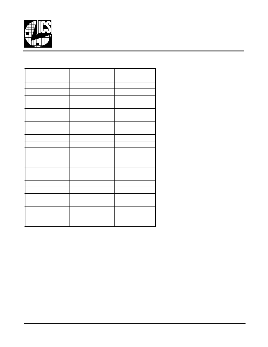
Frequency Table
N
R
E
T
T
A
P
2
0
-
5
9
5
2
S
C
I
4
0
-
5
9
5
2
S
C
I
r
e
d
i
v
i
D
e
c
n
e
r
e
f
e
R
6
4
3
4
R
D
D
A
K
L
C
V
K
L
C
V
K
L
C
V
0
7
2
.
0
0
1
8
2
.
0
5
1
0
9
.
5
2
1
0
6
.
6
5
2
6
0
.
3
9
3
9
.
4
6
3
7
2
.
6
3
2
9
.
1
7
4
6
7
.
0
5
8
0
.
0
8
5
3
0
.
7
5
0
9
.
9
8
6
y
c
n
e
u
q
e
r
F
l
a
n
r
e
t
x
E
3
9
.
2
6
7
8
2
.
5
4
2
9
.
4
7
8
9
9
.
5
3
1
4
1
.
5
2
9
0
2
.
2
3
0
3
.
8
2
A
1
5
.
0
1
1
6
4
.
1
3
B
1
2
.
0
8
6
9
.
5
3
C
1
1
.
0
4
4
0
.
0
4
D
8
2
.
5
4
5
9
.
4
4
E
1
5
.
5
7
4
9
.
9
4
F
9
4
.
5
6
3
9
.
4
6
R
D
D
A
K
L
C
M
K
L
C
M
K
L
C
M
0
2
4
.
0
4
0
2
.
0
4
1
9
5
.
5
4
4
5
.
1
4
2
A
/
N
4
5
.
4
4
3
A
/
N
1
6
.
9
4

12
ICS2595
ICS XXXX N-SXX
Example:
Package T ype
N=DIP (Plastic)
M=SOIC
Device Type (consists of 3 or 4 digit numbers)
ICS, AV=Standard Device; GSP=Genlock Device
Prefix
Ordering Information
ICS2595
S=Strobe Option/XX=Default Freq2uencies
Where:
"S" denotes strobe option:
"XX"denotes default frequencies:
D - Negative edge triggered
20 PIN SOIC Package
20 PIN DIP Package