 | –≠–ª–µ–∫—Ç—Ä–æ–Ω–Ω—ã–π –∫–æ–º–ø–æ–Ω–µ–Ω—Ç: 70T16 | –°–∫–∞—á–∞—Ç—å:  PDF PDF  ZIP ZIP |
1
©2002 Integrated Device Technology, Inc.
AUGUST 2002
DSC 5663/1
I/O
Control
Address
Decoder
MEMORY
ARRAY
ARBITRATION
INTERRUPT
SEMAPHORE
LOGIC
Address
Decoder
I/O
Control
R/
W
L
CE
L
OE
L
BUSY
L
A
13L(1)
A
0L
5663 drw 01
I/O
0L
- I/O
8L
CE
L
OE
L
R/
W
L
SEM
L
INT
L
M/
S
BUSY
R
A
13R(1)
A
0R
SEM
R
INT
R
CE
R
OE
R
(3)
(2,3)
(3)
R/
W
R
CE
R
OE
R
R/
W
R
14
14
I/O
0R
-I/O
8R
(2,3)
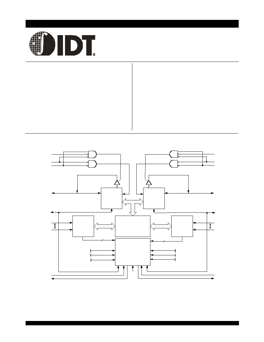
.unctional Block Diagram
x
M/
S = V
IH
for
BUSY output flag on Master
M/
S = V
IL
for
BUSY input on Slave
x
Busy and Interrupt Flag
x
On-chip port arbitration logic
x
Full on-chip hardware support of semaphore signaling
between ports
x
Fully asynchronous operation from either port
x
LVTTL-compatible, single 2.5V (±100mV) power supply
x
Available in an 80-pin TQFP and 100-pin fpBGA
x
Industrial temperature range (≠40∞C to +85∞C) is available
for selected speeds
.eatures
x
True Dual-Ported memory cells which allow simultaneous
reads of the same memory location
x
High-speed access
≠ Commercial:20/25ns (max.)
≠ Industrial: 25ns (max.)
x
Low-power operation
≠ IDT70T16/5L
Active: 200mW (typ.)
Standby: 600
µ
W (typ.)
x
IDT70T16/5 easily expands data bus width to 18 bits or
more using the Master/Slave select when cascading more
than one device
HIGH-SPEED 2.5V
16/8K X 9 DUAL-PORT
STATIC RAM
IDT70T16/5L
NOTES:
1. A
13
is a NC for IDT70T15.
2. (MASTER):
BUSY is output; (SLAVE): BUSY is input.
3.
BUSY outputs and INT outputs are non-tri-stated push-pull drivers.
PRELIMINARY

6.42
IDT70T16/5L
High-Speed 2.5V 16/8K x 9 Dual-Port Static RAM Industrial and Commercial Temperature Ranges
2
PRELIMINARY
Description
The IDT70T16/5 is a high-speed 16/8K x 9 Dual-Port Static RAM.
The IDT70T16/5 is designed to be used as stand-alone Dual-Port RAMs
or as a combination MASTER/SLAVE Dual-Port RAM for 18-bit-or-more
wider systems. Using the IDT MASTER/SLAVE Dual-Port RAM ap-
proach in 18-bit or wider memory system applications results in full-speed,
error-free operation without the need for additional discrete logic.
This device provides two independent ports with separate control,
address, and I/O pins that permit independent, asynchronous access for
reads or writes to any location in memory. An automatic power down
feature controlled by
CE permits the on-chip circuitry of each port to enter
a very low standby power mode.
Fabricated using IDT's CMOS high-performance technology, these
devices typically operate on only 200mW of power.
The IDT70T16/5 is packaged in an 80-pinTQFP (Thin Quad Flatpack)
and a 100-pin fpBGA (fine pitch Ball Grid array) .
Pin Configurations
(1,2,3,4)
NOTES:
1. A
13
is a NC for IDT70T15.
2. All V
DD
pins must be connected to power supply.
3. All V
SS
pins must be connected to ground supply.
4. Package body is approximately 1.18 in x 1.18 in x 0.16 in.
5. This package code is used to reference the package diagram.
6. This text does not imply orientation of Part-marking.
INDEX
IDT70T16/5PF
PN80-1
(5)
80-Pin TQFP
Top View
(6)
8
9
10
11
12
13
14
15
16
1
2
3
4
5
6
7
58
57
56
55
54
53
52
51
50
49
48
47
46
59
60
45
6
5
6
6
6
7
6
8
7
9
7
8
7
7
7
6
7
5
7
4
7
3
7
2
7
1
7
0
6
9
8
0
I/O
2L
V
SS
V
SS
A
4R
BUSY
L
BUSY
R
INT
R
INT
L
V
SS
M/
S
O
E
L
N
C
R
/
W
L
C
E
L
S
E
M
L
V
D
D
N
C
O
E
R
C
E
R
R
/
W
R
S
E
M
R
V
S
S
I/O
3L
I/O
4L
I/O
5L
I/O
6L
I/O
7L
I/O
0R
I/O
1R
I/O
2R
V
DD
I/O
3R
I/O
4R
I/O
5R
I
/
O
8
R
A
1
2
R
A
1
1
R
A
1
0
R
A
9
R
A
3R
A
2R
A
1R
A
0R
A
0L
A
1L
A
2L
A
3L
A
4L
A
6
L
A
7
L
A
8
L
A
9
L
A
1
0
L
A
1
1
L
A
1
2
L
I
/
O
0
L
17
18
19
20
I/O
6R
I
/
O
7
R
NC
V
DD
2
3
2
4
3
6
3
5
3
4
3
3
3
2
3
1
3
0
2
9
2
8
2
7
2
6
2
5
4
0
3
9
3
8
3
7
A
8
R
A
7
R
A
6
R
N
C
44
43
42
41
NC
A
5L
NC
6
1
6
2
6
3
6
4
I
/
O
8
L
I
/
O
1
L
5663 drw 02
N
C
N
C
N
C
N
C
NC
A
5
R
NC
NC
N
C
2
1
2
2
A
1
3
L
(
1
)
A
1
3
R
(
1
)
,
07/11/02

6.42
IDT70T16/5L
High-Speed 2.5V 16/8K x 9 Dual-Port Static RAM Industrial and Commercial Temperature Ranges
3
PRELIMINARY
Pin Configurations
(con't.)
(1,2,3,4)
C10
I/O
3R
D8
NC
C8
NC
A9
NC
D9
I/O
5R
C9
NC
B9
I/O
8R
D10
I/O
1R
C7
CE
R
B8
OE
R
A8
R/
W
R
A10
I/O
7R
D7
SEM
R
B7
A7
NC
B6
C6
NC
D6
A5
V
SS
B5
NC
C5
NC
D5
A
11R
A4
NC
B4
A
10R
C4
A
7R
D4
NC
A3
A
12R
B3
A
8R
C3
A
5R
D3
A
2R
D2
INT
R
C2
A
4R
B2
NC
A2
A
9R
A1
A
6R
B1
NC
C1
A
3R
D1
A
1R
E1
M/
S
E2
BUSY
R
E3
A
0R
E4
A
1L
F1
V
SS
F2
BUSY
L
F3
A
0L
F4
NC
G1
INT
L
G2
A
3L
G3
A
6L
G4
NC
H1
A
2L
H2
A
5L
H3
A
10L
H4
NC
J1
A
4L
J2
A
8L
J3
A
11L
J4
NC
K1
A
7L
K2
A
9L
K3
A
12L
K4
NC
A6
V
SS
B10
I/O
6R
E5
V
SS
E6
V
SS
E7
I/O
4R
E8
I/O
2R
E9
I/O
0R
E10
V
DD
F5
V
DD
F6
V
SS
F8
I/O
5L
F9
I/O
6L
F10
I/O
7L
G5
NC
G6
SEM
L
G7
NC
G8
I/O
3L
G9
V
SS
G10
I/O
4L
H5
NC
H6
CE
L
H7
I/O
8L
H8
NC
H9
NC
H10
I/O
2L
J5
NC
J6
J7
R/
W
L
J8
NC
J9
V
SS
J10
I/O
1L
K5
V
DD
K6
V
DD
K7
NC
K8
NC
K9
OE
L
K10
I/O
0L
F7
V
DD
5 6 63 d rw 0 3
,
08/14/02
A
13R
(1)
A
13L
(1)
NC
NC
IDT70T16/5BF
BF100
(5)
100-Pin fpBGA
Top View
(6)
2. All V
DD
pins must be connected to power supply.
3. All V
SS
pins must be connected to ground.
4. BF-100 package body is approximately 10mm x 10mm x 1.4mm with 0.8mm ball pitch.
NOTES:
1. A
13
is a NC for IDT70T15.
5. This package code is used to reference the package diagram.
6. This text does not indicate orientation of the actual part marking.

6.42
IDT70T16/5L
High-Speed 2.5V 16/8K x 9 Dual-Port Static RAM Industrial and Commercial Temperature Ranges
4
PRELIMINARY
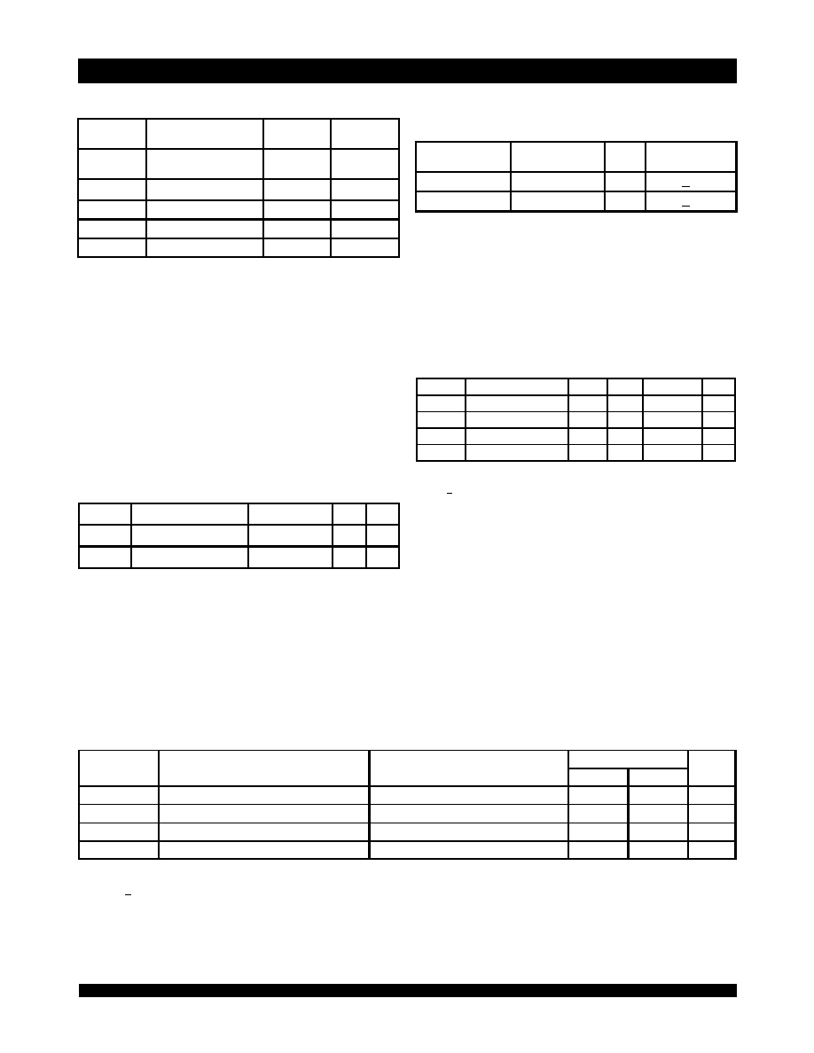
Pin Names
Left Port
Right Port
Names
CE
L
CE
R
Chip Enable
R/W
L
R/W
R
Read/Write Enable
OE
L
OE
R
Output Enable
A
0L
- A
13L
(1)
A
0R
- A
13R
(1)
Address
I/O
0L
- I/O
8L
I/O
0R
- I/O
8R
Data Input/Output
SEM
L
SEM
R
Semaphore Enable
INT
L
INT
R
Interrupt Flag
BUSY
L
BUSY
R
Busy Flag
M/S
Master or Slave Select
V
DD
Power (2.5V)
V
SS
Ground (0V)
5663 tbl 01
Truth Table II: Semaphore Read/Write Control
(1)
Truth Table I: Non-Contention Read/Write Control
NOTE:
1. There are eight semaphore flags written to via I/O
0
and read from all I/O
s
(I/O
0
-I/O
8
). These eight semaphores are addressed by A
0
- A
2.
NOTE:
1. Condition: A
0L
-- A
13L
A
0R
-- A
13R
Inputs
(1)
Outputs
Mode
CE
R/
W
OE
SEM
I/O
0-8
H
X
X
H
High-Z
Deselcted: Power-Down
L
L
X
H
DATA
IN
Write to Memory
L
H
L
H
DATA
OUT
Read Memory
X
X
H
X
High-Z
Outputs Disabled
5663 tbl 02
Inputs
Outputs
Mode
CE
R/
W
OE
SEM
I/O
0-8
H
H
L
L
DATA
OUT
Read Semaphore Flag Data Out (I/O
0
- I/O
8
)
H
X
L
DATA
IN
Write I/O
0
into Semaphore Flag
L
X
X
L
____
Not Allowed
5663 tbl 03
NOTE:
1. A
13
is a NC for IDT70T15.
6.42
IDT70T16/5L
High-Speed 2.5V 16/8K x 9 Dual-Port Static RAM Industrial and Commercial Temperature Ranges
5
PRELIMINARY
Recommended DC Operating
Conditions
Maximum Operating
Temperature and Supply Voltage
(1)
Absolute Maximum Ratings
(1)
NOTES:
1. Stresses greater than those listed under ABSOLUTE MAXIMUM RATINGS may
cause permanent damage to the device. This is a stress rating only and
functional operation of the device at these or any other conditions above
those indicated in the operational sections of this specification is not implied.
Exposure to absolute maximum rating conditions for extended periods may
affect reliability.
2. V
TERM
must not exceed V
DD
+ 0.3V.
3. Ambient Temperature Under Bias. No AC Conditions. Chip Deselected.
NOTES:
1. This is the parameter T
A
. This is the "instant on" case temperature.
S y m b o l
R a tin g
C o m m e rcia l
& In du s trial
U n it
V
TERM
(2 )
Te rm in a l V o lta g e
w ith R e s p e c t to G N D
-0 . 5 to + 3 . 6
V
T
BIAS
(3 )
Te m p e ra tu re U n d e r B ia s
-5 5 to + 1 2 5
o
C
T
STG
S to ra g e Te m p e ra tu re
-6 5 to + 1 5 0
o
C
T
JN
J u n c tio n Te m p e ra tu re
+ 1 5 0
o
C
I
OUT
D C O u tp u t C u rre n t
5 0
m A
5 6 63 tb l 04
Grade
Am bient
Tem perature
GND
V
DD
Co m m e rc ial
0
O
C to + 70
O
C
0V
2.5V
+
100m V
Ind ustrial
-40
O
C to + 85
O
C
0V
2.5V
+
100m V
5663 tbl 05
S y m b o l
P aram eter
M in .
T yp .
M ax.
Un it
V
D D
S u p p ly Vo lta g e
2 . 4
2 . 5
2 . 6
V
V
S S
G ro u n d
0
0
0
V
V
IH
In p u t H ig h Vo lta g e
1 . 7
_ __ _
V
D D
+ 0 . 3
(2 )
V
V
IL
In p u t L o w V o lta g e
-0 .3
(1 )
_ __ _
0 . 7
V
5 6 63 tb l 06
Capacitance
(1)
(T
A
= +25∞C, f = 1.0MHz)
NOTES:
1. This parameter is determined by device characteristics but is not production
tested.
2. 3dV references the interpolated capacitance when the input and output signals
switch from 0V to 3V or from 3V to 0V .
Sym bol
Param eter
Conditions
(2)
M ax.
Unit
C
IN
Inp ut Cap acitanc e
V
IN
= 3d V
9
p F
C
O U T
Outp ut Cap ac itance
V
O U T
= 3d V
10
p F
5663 tbl 07
DC Electrical Characteristics Over the
Operating Temperature and Supply Voltage Range
(V
DD
= 2.5V ± 100mV)
NOTE:
1.
At V
DD
< 2.0V, Input leakages are undefined.
S y m bo l
P ara m eter
T est C on d itio ns
70T 16/ 5L
Un it
M i n .
M a x.
|I
LI
|
Inp ut Le ak ag e C urre nt
(1 )
V
D D
= 2.6V, V
IN
= 0V to V
D D
__ _
5
µ A
|I
LO
|
O utp ut L e ak ag e C urre nt
CE = V
IH
, V
O U T
= 0V to V
D D
__ _
5
µ A
V
O L
O utp ut L o w Vo ltag e
I
O L
= + 2m A
__ _
0. 4
V
V
OH
O utp ut H ig h Vo ltag e
I
OH
= -2m A
2. 0
__ _
V
5663 tb l 0 8
NOTES:
1. V
IL
> -1.5V for pulse width less than 10ns.
2. V
TERM
must not exceed V
DD
+ 0.3V.