 | –≠–Ľ–Ķ–ļ—ā—Ä–ĺ–Ĺ–Ĺ—č–Ļ –ļ–ĺ–ľ–Ņ–ĺ–Ĺ–Ķ–Ĺ—ā: 79RC32364 | –°–ļ–į—á–į—ā—Ć:  PDF PDF  ZIP ZIP |

1 of 21
June 20, 2000
2000 Integrated Device Technology, Inc.
*Notice: The information in this document is subject to change without notice
DSC 4510
Block Diagram
Block Diagram
Block Diagram
Block Diagram
The IDT logo is a registered trademark and ORION, RC4650, RC4640, RV4640, RC4600, RC3081, RC3052, RC3051, RC3041, RISController, and RISCore are trademarks of Integrated Device Technology, Inc.
System Control
Coprocessor (CPO)
2kB D-Cache, 2-set,
Clock
En
hanc
ed JTAG (
I
CE I
n
t
e
rf
ace
)
TLB
MMU
lockable, write-back/write-through
Generation
Unit
RC32364 Bus Interface Unit
8kB I-Cache,
lockable
2-set,
RISCore32300 Internal Bus Interface
RISCore4000 Compatible
w/
RISCore32300
TM
Extended MIPS 32
Integer CPU Core
Features
Features
Features
Features
x
High-performance embedded RISController
TM
microprocessor, based on IDT RISCore32300
TM
32-bit CPU
core
≠ Based on MIPS 32 RISC architecture with enhancements
≠ Scalar 5-stage pipeline minimizes branch and load delays
≠ 66 Million multiply accumulate (MAC) Mul-Add/second
@ 133MHz
≠ 100 and 133 frequencies
x
MIPS 32 (ISA) instruction set architecture
≠ MIPS IV compatible conditional move instructions
≠ MIPS IV superset PREF (prefetch) instruction
≠ Fast multiplier with atomic multiply-add, multiply-sub
≠ Count leading zeros/ones instructions
x
Large, efficient on-chip caches
≠ Separate 8kB Instruction cache and 2kB Data cache
≠ 2-way set associative
≠ Write-back and write-through support on a per page basis
≠ Optional cache locking with "per line" resolution, to facilitate
deterministic response
≠ Simultaneous instruction and data fetch in each clock cycle,
sustained rate, achieves over 1 GB/sec bandwidth
x
Flexible RC4000 compatible MMU with 32-page TLB on-chip
≠ Variable page size
≠ Variable number of locked entries
≠ No performance penalty for address translation
x
Flexible bus interface allows simple, low-cost designs
≠ Bus interface runs at a fraction of pipeline rate
≠ Programmable port-width interface (8-,16-, 32-bit memory and
I/O regions)
≠ Programmable bus turnaround times (BTA)
≠ Supports single data or burst transactions
x
Improved real-time support
≠ Fast interrupt decode
x
Low-power operation
≠ Active power management: powers down inactive units
≠ Typical power 700mW @ 133MHz
≠ Stand-by mode <300mW
x
Enhanced JTAG interface, for low-cost in-circuit emulation
(ICE)
x
MIPS architecture ensures applications software
compatibility throughout the RISController series of
embedded processors
x
Industrial temperature range support
x
3.3V operation (core and I/O)
79RC32364
TM
RISController
TM
Embedded 32-bit
Microprocessor, based on
RISCore32300
2 of 21
June 20, 2000
79RC32364TM
*Notice: The information in this document is subject to change without notice
Device
Device
Device
Device Ov
Ov
Ov
Overview
erview
erview
erview
Targeted to a variety of performance-hungry, cost-sensitive
embedded applications, the RC32364 is a new low-powered, low-cost
member of the Integrated Device Technology, Inc. (IDT) RISController
Series of Embedded Microprocessors.
The RC32364 brings 64-bit performance levels to lower cost
systems. High performance is achieved through the use of advanced
techniques such as large on-chip two-way set-associative caches, a
streamlined high-speed pipeline, high-bandwidth, and facilities such as
early restart for data cache misses. Also, through IDT proprietary
enhancements to the base MIPS architecture, the processor's perfor-
mance, in particular applications, is further extended.
The RC32364 is the first member of a new processor family that uses
IDT's proprietary RISCore32300 CPU core. The RISCore32300 core
continues IDT's tradition of high-performance through high-speed pipe-
lines, high-bandwidth caches, and architectural extensions that serve
the needs of specific markets; yet the RC32364 provides these capabili-
ties in a low-cost, high-speed 32-bit enhanced MIPS architecture core,
enabling a new level of price performance.
Around the RISCore32300, the RC32364 integrates a fully RC5000
compatible memory management unit (MMU), substantial amounts of
efficient cache memory, an enhanced debug capability, digital signal
processing (DSP) extensions, and a low-cost system interface. The
resulting device is well suited to the needs of mid-range communications
equipment, xDSL equipment, and consumer devices.
Also, being upwardly software compatible with the RC3000 family,
the RC32364 will serve in many of the same applications as well as
support applications that require integer DSP functions.
Device Performance
Device Performance
Device Performance
Device Performance
RC32364 is rated at 175 dhrystone MIPS at 133MHz. The internal
cache bandwidth is over 1.2 GB/sec, with external bus bandwidth of
260MB/sec. Computational performance is further enhanced by the
device's DSP capability, which supports 66 Million multiply-accummulate
(MAC) operations per second at 133MHz.
The RISCore32300 uses a 5-stage pipeline, similar to the
RISCore3000 and the RISCore4000 processor families. The simplicity
of the pipeline enables the processor to achieve high frequency while
minimizing device complexity, reducing both cost and power consump-
tion. Because this pipeline is not sensitive to the data conflicts that slow-
down super-scalar machines, an added benefit to this pipeline approach
is that sustained actual performance is much closer to the theoretical
maximum performance.
The RISCore32300 integer execution unit implements the MIPS 32
ISA. The RISCore32300 thus implements a load/store architecture with
single-cycle ALU operations (logical, shift, add, subtract) and an autono-
mous multiply/divide unit. The 32-bit register resources include 32
general-purpose orthogonal integer registers, the HI/LO result register
for the integer multiply/divide unit, and the program counter.
RISCore32300 CPU core features include:
x
MIPS IV prefetch operations, with various innovative hint
subfields
x
MIPS IV compatible conditional move instructions
x
MAD, MUL and MSUB instructions added to the integer multiply
units
x
Two new instructions: Count Leading Ones (CLO) and Counts
Leading Zeros (CLZ)
These integer unit enhancements combine to make the CPU well
suited to applications that require high bandwidth, rapid computation,
and/or DSP capability.
The RISCore32300 register file has 32 general-purpose 32-bit
registers that are used for scalar integer operations and address calcu-
lation. The register file consists of two read ports and two write ports
and is fully bypassed to minimize operation latency in the pipeline.
The RISCore32300 arithmetic logic unit (ALU) consists of the
integer adder and logic unit. The adder performs address calculations in
addition to arithmetic operations; the logic unit performs all of the logic
and shift operations. Each unit is highly optimized and can perform an
operation in a single pipeline cycle.
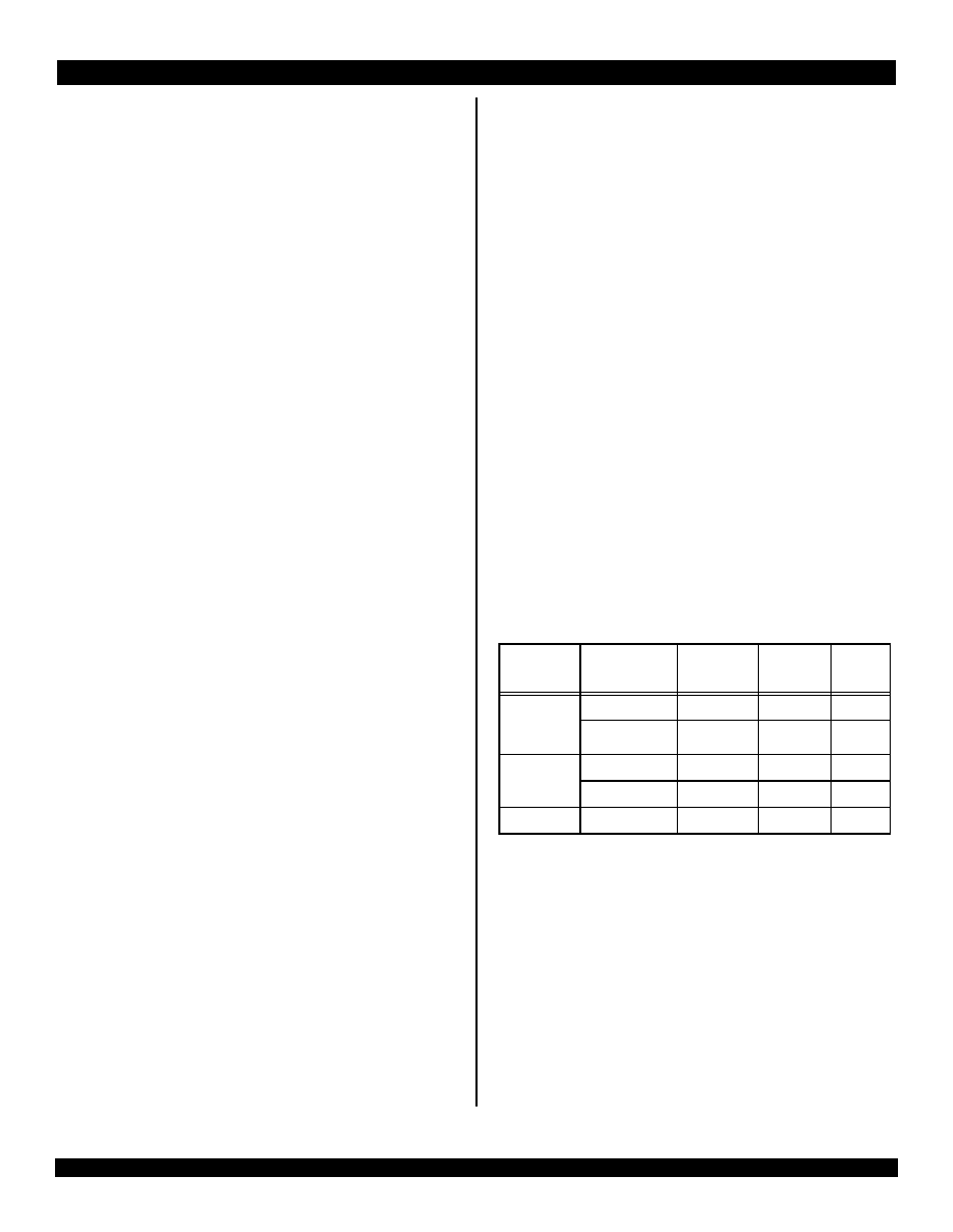
The RC32364 uses a dedicated integer multiply/divide unit, opti-
mized for high-speed multiply and multiply-accumulate operations.
Table 1 lists the repeat rate (peak issue rate of cycles until the operation
can be reissued), latency (number of cycles until a result is available),
and number of processor stalls (number of cycles that the CPU will
always delay the pipeline) required for these operations. Each rate listed
is expressed in terms of pipeline clocks.
The original MIPS architecture defines that the results of a multiply
or divide operation are placed in the HI and LO registers. Using the
move-from-HI (MFHI) and move-from-LO (MFLO) instructions, these
values can then be transferred to the general purpose register file.
As an enhancement to the original MIPS ISA, the RC32364 imple-
ments an additional multiply instruction, MUL, which specifies that
multiply results bypass the LO register and be placed immediately into
the primary register file. By avoiding the explicit MFLO instruction,
required when using LO, and by supporting multiple destination regis-
ters, the throughput of multiply-intensive operations is increased.
Opcode
Operand
Size
Latency Repeat
Stall
MULT/U,
MAD/U
MSUB/U
16 bit
3
2
0
32 bit
4
3
0
MUL
16 bit
3
2
1
32 bit
4
3
2
DIV, DIVU
any
36
36
0
Table 1 RISCore32300 Integer Multiply/Divide Unit Operation Frequency

3 of 21
June 20, 2000
79RC32364TM
*Notice: The information in this document is subject to change without notice
Two atomic operations--multiply-add (MAD) and multiply-subtract
(MSUB)--are used to perform the multiply-accumulate and multiply-
subtract operations. The MAD instruction multiplies two numbers and
then adds the product to the current contents of the HI and LO registers.
Similarly, the MSUB instruction multiplies two operands and then
subtracts the product from the HI and LO registers.
The MAD and MSUB operations are used in numerous DSP algo-
rithms and allow the RC32364 to cost reduce systems requiring a mix of
DSP and control functions.
Finally, for these operations, aggressive implementation techniques
feature low latency along with pipelining to allow the issuance of new
operations before a previous operation has been completed. The
RC32364 also performs automatic operand size detection and imple-
ments hardware interlocks to prevent overrun, achieving high-perfor-
mance with simple programming.
System Control Coprocessor (CP0)
System Control Coprocessor (CP0)
System Control Coprocessor (CP0)
System Control Coprocessor (CP0)
In the MIPS architecture, the system control co-processor is respon-
sible for the virtual-to-physical address translation and cache protocols,
the exception control system, and the processor's diagnostics capability.
Also, the system control co-processor (and thus the kernel software) is
implementation dependent.
Although the RISCore32300 implements a 32-bit ISA, the Memory
Management Unit (MMU) that the RC32364 incorporates is modeled
after the MMU found in the 64-bit RC5000 family and offers variable
page size, enhanced cache write algorithm support, mapping of a larger
portion of the virtual address space and a variable number of locked
entries, relative to the traditional 32-bit R3000 style MMU.
The RC32364's translation lookaside buffer (TLB) contains 16
entries, mapping a total of 32 pages or as much as 512 MB of memory
at a time.
The exception model that is implemented in the RC32364 is also
consistent with that of the RC5000 family, including the treatment of
kernel mode and exception processing.
The RC32364 incorporates all system control co-processor (CP0)
registers on-chip. These registers provide the path through which the
virtual memory system's address translation is controlled, exceptions
are handled, and operating modes are selected (for example, kernel vs.
user mode, interrupts enabled or disabled, and cache features).
In addition, the RC32364 includes registers to implement a real-time
cycle counting facility, which aids in cache diagnostic testing, assists in
data error detection, and facilitates software debug. Alternatively, this
timer can be used as the operating system reference timer and can
signal a periodic interrupt.
Operation Modes
Operation Modes
Operation Modes
Operation Modes
The RC32364 supports two modes of operation: user mode and
kernel mode. User mode is most often used for applications programs,
and the kernel mode is typically used for handling exceptions and oper-
ating system kernel functions, including CP0 management and I/O
device access.
The processor enters kernel mode at reset and when an exception is
recognized. While in kernel mode, software has access to the entire
address space as well as all of the CP0 registers. User mode accesses
are limited to a subset of the virtual address space and can be inhibited
from accessing CP0 functions.
Virtual-to-Physical Address Mapping
Virtual-to-Physical Address Mapping
Virtual-to-Physical Address Mapping
Virtual-to-Physical Address Mapping
The RC32364's 4GB virtual address space is divided into addresses
that are accessible in either kernel or user mode (kuseg) and those that
are accessible only in kernel mode (kseg2:0).
Bits in a status register determine which virtual addressing mode will
be used. While in user mode, the RC32364 provides a single, uniform
2GB virtual address space for the user's program. While operating in
kernel mode, four distinct virtual address spaces, totalling 4GB, are
simultaneously available and are differentiated by the high-order bits of
the virtual address.
The RC32364 reserves a small portion of the kernel address space
for on-chip resources. These resources include those used by the
Enhanced JTAG unit as well as registers used to configure the system
bus interface.
For fast virtual-to-physical address decoding, the RC32364 uses a
fully associative translation lookaside buffer (TLB) that maps 32
virtual pages to their corresponding physical addresses. The TLB is
organized as 16 pairs of even/odd entries mapping pages of sizes that
vary from 4kBytes to 16 MBytes into the 4GB physical address space.
To assist in controlling both the amount of mapped space and the
replacement characteristics of various memory regions, the RC32364
provides two mechanisms. First, the page size can be configured, on a
per entry basis, to map a page size of 4kB to 16MB (in multiples of 4). A
CP0 register is loaded with the mapping page size which is then entered
into the TLB when a new entry is written. Thus, operating systems can
provide special purpose maps; for example, a typical frame buffer can
be memory mapped with only one TLB entry.
The second mechanism controls the replacement algorithm, when a
TLB miss occurs. To select a TLB entry to be written with a new
mapping, the RC32364 provides a random replacement algorithm;
however, the processor provides a mechanism whereby a system
specific number of mappings can be locked into the TLB and thus avoid
being randomly replaced. This facilitates the design of real-time
systems, by allowing deterministic access to critical software.
The RC32364's TLB also contains information to control the cache
coherency protocol for each page. Specifically, each page has attribute
bits to determine whether the coherency algorithm is uncached, non-
coherent write-back, or non-coherent write-through no write-allocate.

4 of 21
June 20, 2000
79RC32364TM
*Notice: The information in this document is subject to change without notice
This allows the system architect to allocate address space according to
the most efficient use of bus bandwidth. For example, stack data may be
accessed always as write-back, while packet data may be best
accessed as write through, for later DMA out to an I/O port.
The RC32364 cache controller works in conjunction with these
attributes, enabling an application to alias a region of physical memory
through multiple virtual spaces. The cache controller will also ensure
that regardless of which address space is used the current copy of data
will be provided when referenced, and it will further guarantee that the
cache is properly managed with respect to main memory.
Debug Support
Debug Support
Debug Support
Debug Support
To facilitate software debug, the RC32364 adds a pair of watch regis-
ters to CP0. When enabled, these registers will cause the CPU to take
an exception when a "watched" address is appropriately accessed.
In addition, the RC32364 implements an Enhanced JTAG interface,
which requires the inclusion of significant amounts of debug support
logic on-chip, facilitating the development of low-cost in-circuit emulation
equipment.
For low-cost In-Circuit Emulation, the RC32364 provides an
Enhanced JTAG interface. This interface consists of two modes of
operation: Run-Time Mode and Real-Time Mode.
The Run-Time Mode provides a standard JTAG interface for on-chip
debugging, and the Real-Time Mode provides additional status pins--
PCST[2:0]--which are used in conjunction with JTAG pins for Real-Time
Trace information at the processor internal clock or any division of the
pipeline clock.
The RC32364 implements the traditional RC4000 model of interrupt
processing. However, this model has been enhanced to benefit real-
time systems.
To speed interrupt exception decoding, the RC32364 adds a sepa-
rate interrupt vector. Unlike the RC3000 family--which utilizes a single
common exception vector for all exception types (including interrupts)--
the RC32364 allows kernel software to enable a separate interrupt
exception vector.
When enabled, this vector location speeds interrupt processing by
allowing software to avoid decoding interrupts from general purpose
exceptions.
Development Tools
Development Tools
Development Tools
Development Tools
An array of tools facilitate rapid development of RC32364-based
systems, allowing a wide variety of customers to take advantage of the
processor's high-performance capabilities while maintaining short time-
to-market goals.
The RC32364 incorporates an enhanced JTAG debug interface. This
interface uses a small number of pins, combined with on-chip debug
support logic, to enable the development of low-cost in-circuit emulators
for high-speed IDT processors.
Cache Memory
Cache Memory
Cache Memory
Cache Memory
To keep the RC32364's high-performance pipeline full and operating
efficiently, the RC32364 incorporates on-chip instruction and data
caches that can each be accessed in a single processor cycle. Each
cache has its own 32-bit data path and can be accessed in the same
pipeline clock cycle.
The RC32364 incorporates a two-way set associative on-chip
Instruction Cache. This virtually indexed, physically tagged cache is
8kB in size and parity protected. Because this cache is virtually indexed,
the virtual-to-physical address translation occurs in parallel with the
cache access. The tag holds a 21-bit physical address, a valid bit, lock
bit, a parity bit, and the FIFO replacement bit.
For fast, single cycle data access, the RC32364 includes a 2kB on-
chip data cache that is two-way set associative with a fixed 16-byte
(four words) line size. The data cache is protected with byte parity and
its tag is protected with a single parity bit. It is virtually indexed and
physically tagged to allow simultaneous address translation and data
cache access.
The RC32364 supports a cache-locking feature to critical sections
of code and data into on-chip caches, to guarantee fast accesses. The
implementation of cache-locking is on a "per-line" basis, enabling the
system designer to maximize the efficiency of the system cache.
Writes to external memory--whether cache miss write-backs or
stores to uncached or write-through addresses--use the on-chip write
buffer. The write buffer holds a maximum of four address and data
pairs. The entire buffer is used for a data cache writeback and allows
the processor to proceed in parallel with a memory update.
System interfaces
System interfaces
System interfaces
System interfaces
The RC32364 supports a 32-bit system interface, allowing the CPU
to interface with a lower cost memory system. The main features of the
system interface include:
x
Multiplexed address and data bus with Address Latch Enable
(ALE) signal to demultiplex the A/D bus.
x
Support of variable port widths, including boot device.
x
Support of multiple pipeline to system clock ratios, with the CPU
core frequency being derived from the input system clock.
x
Incorporation of a DMA arbiter, allowing an external master
control of the external bus.
The 32-bit system address/data (A/D) bus is used to transfer
addresses and data between the RC32364 and the rest of the system.
The ALE signal is provided to demultiplex the address from this bus.
The DATAEN* signal indicates the data phase of the A/D bus and DT/R*
indicates the direction of data flow. BE*[3:0] indicates the valid bytes on
the bus. Additional ADDR[3:2] provides incremental address during
burst transfers.
To indicate system interface bus activity, the RC32364 provides a
cycle-in-progress (CIP*) signal. The RD* and WR* signals indicate the
type of cycle in progress. And to terminate cycle in progress, the

5 of 21
June 20, 2000
79RC32364TM
*Notice: The information in this document is subject to change without notice
RC32364 also provides Ack*, Retry*, and BusErr* signals. This device
also provides I/D* signals, to indicate whether instructions or data is
being transferred. The Last* signal is provided to indicate that the last
data transfer is in progress.
The RC32364 provides six external interrupt signals: INT*[5:0] and
a non-maskable interrupt (NMI*) signal.
To share the system interface bus, the RC32364 provides BusReq*
and BusGnt* signals to interface external DMA masters. To allow the
external master control of the external bus, a DMA arbiter is provided.
The RC32364 supports a variable bus width interface, enabling the
CPU to operate with a mix of 8-bit, 16-bit, and 32-bit wide memories.
To indicate the width of the memory or I/O space being accessed, the
RC32364 provides two output signals, Width[1:0]. The width of various
address spaces is programmed using the Port Width Control Register.
The RC32364's physical memory is divided into several regions, and
each region's width can be programmed by using this register. Within
these regions, the bus turnaround time can also be programmed.
Thus, the RC32364 can be simply mated with low-cost external
memory subsystems. The large on-chip caches and the early restart
serve to allow the processor to achieve high-performance even with
such low-cost memory.
The RISCore32300 offers a number of features relevant to low-
power systems, including low-power design, active power manage-
ment and power-down modes of operation. The RISCore32300 is a
static design. The RC32364 supports a WAIT instruction which is
designed to signal the rest of the chip that execution and clocking should
be halted, reducing system power consumption during idle periods.
Thermal Considerations
Thermal Considerations
Thermal Considerations
Thermal Considerations
The RC32364 is a low-power CPU, consuming approximately 0.9W
peak power. Thus, no special packaging considerations are required.
The RC32364 is guaranteed in a case temperature range of 0
į
to
+85
į
C, for commercial temperature devices; - 40
į
to +85
į
for industrial
temperature devices. The type of package, speed (power) of the device,
and airflow conditions affect the equivalent ambient temperature condi-
tions that will meet this specification.
The equivalent allowable ambient temperature, T
A
, can be calculated
using the thermal resistance from case to ambient (
CA
) of the given
package. The following equation relates ambient and case tempera-
tures:
T
A
= T
C
- P *
CA
where P is the maximum power consumption at hot temperature,
calculated by using the maximum I
CC
specification for the device.
Typical values for
CA
at various airflows are shown in Table 2 Note
that the RC32364 implements advanced power management, which
substantially reduces the average power dissipation of the device.
Revision Histor
Revision Histor
Revision Histor
Revision Historyyyy
August 1999: Changed references from MIPS-II to MIPS 32.
Changed references from MIPS-IV to MIPS 64. Changed values in
Clock Parameters Table, System Interface Parameters Table, and
Power Consumption Table. Deleted Several Timing Diagrams. Added
JTAG TIming Diagram.
Jan. 12, 2000: Corrected information regarding the TRST* signal in
Table 3. TRST* requires an external
pull-down on the board.
April 4, 2000: Adjusted values for DCLK in the System Interface
Parameters table. Added Power Curves.
June 20, 2000: Changed times for the Data Output Hold, TDO
Output Delay Time, and TPC Output Delay Time parameters in the
System Interface Parameters table. Revised values for PCST Output
Delay Time in System Interface Parameters table.
CA
Airflow (ft/min)
0
200
400
600
800
1000
144 TQFP
27
22
20
17
15
14
Table 2 Thermal Resistance (
CA) at Various Airflows

6 of 21
June 20, 2000
79RC32364TM
*Notice: The information in this document is subject to change without notice
Figure 1 System Block Diagram
Pin Description Table
Pin Description Table
Pin Description Table
Pin Description Table
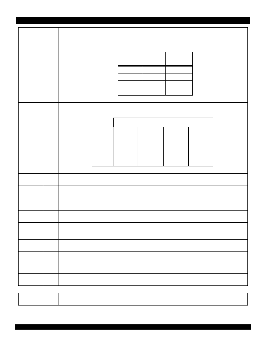
The following is a list of the system interface pins available on the RC32364. Pin names ending with an asterisk (*) are active when low.
Pin
Type
Description
System Interface
AD(31:4)
I/O
Addr(31:4)/Data(31:4)
High-order multiplexed address and data bits. Regardless of system byte ordering, AD(31) is the MSB of the address.
AD(3:0)
I/O
Size(3:0)/Data(3:0)
Valid sizes for the RC32364 are as follows:
Other encodings allow future generations to service other transfer sizes. During the data phase, AD[3:0] represents the Data(3:0).
Addr(3:2)
O
Addr(3:2)
Non-multiplexed address lines. These serve as the word within block address for cache refills (Addr(3:2)). The word within block
address bits count in a sub-block ordering.
ALE
O
Address Latch Enable.
This signal provides set-up and hold times around the address phase of the AD bus.
ADS*
O
Address Strobe
This active-low signal indicates valid address and the start of a new bus transaction. The processor asserts ADS* for the entire
address cycle. This is the inverse of the ALE signal.
Table 3 System Interface Pin Descriptions (Page 1 of 4)
RC32364
Clock
32-bit Data
Bus
RC32134
SDRAM
CPU I/F
DRAM Ctl
Serial
PIO
Timers,
UART,
Interrupt Ctl
DMA
Channels
Memory &
I/O Ctl
Address &
Control
Memory
& I/O
PCI Bridge with Arbiter
32-bit, 33Mhz PCI Bus
Size(3)
Size(2)
Size(1)
Size(0)
Transfer
Width
0
0
0
0
16 bytes
0
0
0
1
1 byte
0
0
1
0
2 bytes
0
0
1
1
3 bytes
0
1
0
0
4 bytes
7 of 21
June 20, 2000
79RC32364TM
*Notice: The information in this document is subject to change without notice
Width(1:0)
O
Bus Width
Indicates the Physical Memory/IO data bus size as follows:
BE*(3:0)
O
ByteEnables(3:0)/Addr(1:0)
Indicates which byte lanes are expected to participate in the transfer.
CIP*
O
Cycle-in-progress
Denotes that a cycle is in progress. Asserted in the address phase and continue asserted until the ACK* for the last data is sampled.
I/D*
O
I/D*
Indicates that the current cycle is for an instruction (active high) or data (active low) transaction.
Rd*
O
Read
This active-low signal indicates that the current transaction is a read.
Wr*
O
Write
This active-low signal indicates that the current cycle transaction is a write.
DataEn*
O
Data Enable
This active-low signal indicates that the AD bus is in data cycle. DEN* is asserted after the address cycle (starting of data cycle), and
deasserted at the end of the last data cycle.
DT/R*
O
Data Transmit/Receive
This active-low signal indicates the current cycle transaction of data direction. "High" is for a write cycle and "Low" is for a read cycle.
Ack*
I
Acknowledge Receiving Data
On read transactions, this signal indicates to the RC32364 that the memory system has placed valid data on the A/D bus, and that
the processor may move the data into the on-chip Read Buffer. On a write transaction, this indicates to the RC32364 that the mem-
ory system has accepted the data on the A/D bus.
Last*
O
Last Data
This active-low output is used to indicate the last data phase of a transfer.
Handshake Interface
BusErr*
I
Bus Error
Indicates that a bus error has occurred.
Pin
Type
Description
Table 3 System Interface Pin Descriptions (Page 2 of 4)
Width(1)
Width(0)
Port
Width
0
0
8 bits
0
1
16 bits
1
0
32 bits
1
1
Reserved
Byte Lanes Enabled In Data Transfer
Port Width
BE(3)
BE(2)
BE(1)
BE(0)
32-bit
Used
Used
Used
Used
16-bit
Byte High
Enable
Not Used
Address Bit 1
(A1)
Byte Low
Enable
8-bit
Not Used
(Driven High)
Not Used
(Driven High)
Address Bit 1
(A1)
Address Bit 0
(A0)

8 of 21
June 20, 2000
79RC32364TM
*Notice: The information in this document is subject to change without notice
Retry*
I
Retry
Indicates that the current bus cycle must be terminated. Retry* is ignored after acceptance of the first data during a read cycle. Dur-
ing a write, Retry* is recognized in all data cycles.
Initialization Interface
ColdReset*
I
ColdReset
This active-low signal is used for power-on reset.
Reset*
I
Reset
This active-low signal is used for both power-on and warm reset.
DMA Interface
BusReq*
I
Bus Request
This active-low signal is an input to the processor that is used to request mastership of the external interface bus. Mastership is
granted according to the assertion of this input, taken back based on its negation.
BusGnt*
I/O
Bus Grant/ModeBit(5)
This active-low signal is an output from the processor and is used to indicate that the CPU has relinquished mastership of the exter-
nal interface bus. BusGnt* goes low initially for at least 2 clocks to indicate that the CPU has relinquished mastership of the external
interface bus. After going low, BusGnt* returns high, either when the CPU makes an internal request for the bus or after BusReq* is
de-asserted.During the power-on reset (Cold Reset), BusGnt* is an input, ModeBit(5).
Interrupt Interface
NMI*
I
Non-Maskable Interrupt
NMI is falling edge sensitive and an asynchronous signal.
Int*(5:0)
I
Interrupt/ModeBit(9:6)
These interrupt inputs are active low to the CPU. During power-on, Int*(3:0) serves as ModeBit(9:6).
Debug Emulator Interface
TCK
I
Testclock
An input test clock, used to shift into or out of the Boundary-Scan register cells. TCK is independent of the system and the processor
clock with nominal 50% duty cycle.
TDI/DINT*
I
TDI/DINT*
On the rising edge of TCK, serial input data are shifted into either the Instruction or Data register, depending on the TAP controller
state. During Real Mode, this input is used as an interrupt line to stop the debug unit from Real Time mode and return the debug unit
back to Run Time Mode (standard JTAG). Requires an external pull-up on the board.
TDO/TPC
O
TDO/TPC
The TDO is serial data shifted out from instruction or data register on the falling edge of TCK. When no data is shifted out, the TDO
is tri-stated. During Real Time Mode, this signal provides a non-sequential program counter at the processor clock or at a division of
processor clock.
TMS
I
TMS
The logic signal received at the TMS input is decoded by the TAP controller to control test operation. TMS is sampled on the rising
edge of the TCK. Requires an external pull-up on the board.
TRST*
I
TRST*
The TRST* pin is an active-low signal for asynchronous reset of the debug unit, independent of the processor logic. Requires an
external pull-down on the board.
DCLK
O
DCLK
Processor Clock. During Real Time Mode, this signal is used to capture address and data from the TDO signal at the processor clock
speed or any division of the internal pipeline.
Pin
Type
Description
Table 3 System Interface Pin Descriptions (Page 3 of 4)

9 of 21
June 20, 2000
79RC32364TM
*Notice: The information in this document is subject to change without notice
PCST(2:0)
I/O
PCST(2:0)/ModeBit(2:0)
PC Trace Status Information
111 (STL) Pipe line Stall
110 (JMP) Branch/Jump forms with PC output
101 (BRT) Branch/Jump forms with no PC output
100 (EXP) Exception generated with an exception vector code output
011 (SEQ) Sequential performance
010 (TST) Trace is outputted at pipeline stall time
001 (TSQ) Trace trigger output at performance time
000 (DBM) Run Debug Mode
During power-on reset (cold reset), PCST(2:0) serves as ModeBit(2:0).
PCST(4:3)
I/O
PCST(4:3)/ModeBit(4:3)
PC Trace Status Information. Reserved Pins for future expansion. During power-on reset, PCST(4:3) serves as ModeBit(4:3).
DebugBoot
I
DebugBoot
The Debug Boot input is used during reset and forces the CPU core to take a debug exception at the end of the reset sequence
instead of a reset exception. This enables the CPU to boot from the ICE probe without having the external memory working. This
input signal is level sensitive and is not latched internally. This signal will also set the JtagBrk bit in the JTAG_Control_Register[12].
Clock/Control Interface
MasterClk
I
MasterClock
This input clock is the bus clock. The core frequency is derived by multiplying this clock up.
VccP
I
VccP
Quiet Vcc for PLL.
VssP
I
VssP
Quiet Vss for PLL.
Vcc I/O
I
Supply voltage for output buffers.
Vcc Core
I
Supply voltage for internal logic.
Vss
I
Ground.
Pin
Type
Description
Table 3 System Interface Pin Descriptions (Page 4 of 4)

10 of 21
June 20, 2000
79RC32364TM
*Notice: The information in this document is subject to change without notice
Logic Diagram
Logic Diagram
Logic Diagram
Logic Diagram
Figure 2 illustrates the direction and functional groupings for the processor signals of the RC32364.
Figure 2 Logic Diagram for RC32364
AD(31:4)
ALE
ADS*
Width(1:0)
BE(3:0)*
CIP*
MasterClk
ColdReset*
Reset*
V
CC
P
V
SS
P
Initial
i
zation
Interr
upt
RC32364
Logic
Symbol
28
6
Interface
AD(3:0)
Addr(3:2)
4
I/D*
Rd*
Wr*
DataEn*
DT/R*
Ack*
Last*
2
NMI
*
Int*(5:0)
DMA Interface
BusReq*
BusGnt*
TCK
TDI/DINT*
TMS
TRST*
DCLK
PCST(2:0)
PCST(4:3)
DebugBoot
TDO/TPC
Bus Err*
Retry*
Hands
h
a
k
e
S
i
gnals
4
2
3
2
Interface
Debug E
m
ulator
Interface
Cl
ock/Control Interface
S
y
stem I
n
terface
Vcc I/O
Vcc Core
Vss

11 of 21
June 20, 2000
79RC32364TM
*Notice: The information in this document is subject to change without notice
RC32364 144-pin TQFP Package Pin-Out
RC32364 144-pin TQFP Package Pin-Out
RC32364 144-pin TQFP Package Pin-Out
RC32364 144-pin TQFP Package Pin-Out
Note that the asterisk (*) identifies an active-low pin. For maximum flexibility and future design compatibility, N.C. pins should be left floating.
Pin
Function
Pin
Function
Pin
Function
Pin
Function
1
Vcc I/O
37
NC
73
NC
109
NC
2
Vss
38
NC
74
NC
110
CIP*
3
TRST*
39
NC
75
NC
111
AD28
4
TDO/TPC*
40
NC
76
ADS*
112
Vss
5
TMS
41
Addr3
77
AD16
113
Vcc I/O
6
Vcc I/O
42
Vcc I/O
78
Vss
114
AD3
7
Vss
43
Vss
79
Vcc I/O
115
AD27
8
TCK
44
AD10
80
AD15
116
DataEn*
9
TDI/DINT*
45
ADDR2
81
I/D*
117
AD4
10
DebugBoot
46
BusReq*
82
VssP
118
Vss
11
PCST4
47
AD11
83
VccP
119
Vcc I/O
12
Vcc Core
48
Vcc I/O
84
NC
120
AD26
13
Vss
49
Vss
85
NC
121
AD5
14
PCST3
50
AD20
86
NC
122
DT/R*
15
NMI*
51
BE3
87
NC
123
AD25
16
INT0*
52
ColdReset*
88
MasterClk
124
Vss
17
PCST2
53
BusGNT*
89
Vss
125
Vcc Core
18
Vcc I/O
54
AD12
90
Vcc I/O
126
AD6
19
Vss
55
Vcc Core
91
AD31
127
AD24
20
DClk
56
Vss
92
AD0
128
AD7
21
INT1*
57
AD19
93
Ack*
129
AD23
22
Vcc Core
58
BE2
94
ALE
130
Vss
23
INT2*
59
Width1
95
Vss
131
Vcc I/O
24
Reset*
60
AD13
96
Vcc Core
132
AD8
25
Vcc Core
61
Vcc I/O
97
AD30
133
Vss
26
Vss
62
Vss
98
AD1
134
AD22
27
Wr*
63
AD18
99
Vcc Core
135
AD9
28
Rd*
64
BE1
100
BusErr*
136
Vss
29
PCST1
65
Width0
101
Retry*
137
Vcc I/O
30
INT3*
66
AD14
102
AD29
138
AD21
31
Vcc I/O
67
Vcc I/O
103
Vss
139
NC
32
Vss
68
Vss
104
Vcc I/O
140
NC
33
INT4*
69
AD17
105
AD2
141
NC
34
PCST0
70
BE0
106
Last*
142
Vss
35
INT5*
71
NC
107
NC
143
NC
36
NC
72
NC
108
NC
144
NC
12 of 21
June 20, 2000
79RC32364TM
*Notice: The information in this document is subject to change without notice
Absolute Maximum Ratings
Absolute Maximum Ratings
Absolute Maximum Ratings
Absolute Maximum Ratings
Note: Stresses greater than those listed under ABSOLUTE MAXIMUM RATINGS may cause permanent damage to the device. This is a
stress rating only and functional operation of the device at these or any other conditions above those indicated in the operational sections of
this specification is not implied. Exposure to absolute maximum rating conditions for extended periods may affect reliability.
Recommended Operation Temperature and Supply Voltag
Recommended Operation Temperature and Supply Voltag
Recommended Operation Temperature and Supply Voltag
Recommended Operation Temperature and Supply Voltageeee
A
A
A
AC Electrical Characteristics -- Commercial/Industrial Temperature
C Electrical Characteristics -- Commercial/Industrial Temperature
C Electrical Characteristics -- Commercial/Industrial Temperature
C Electrical Characteristics -- Commercial/Industrial Temperature
Ranges--RC32364
Ranges--RC32364
Ranges--RC32364
Ranges--RC32364
V
CC
Core & V
CC
I/O = 3.3V
Ī
5%; T
Case
= 0
į
C to +85
į
C Commercial, T
Case
= -40
į
C to +85
į
C Industrial
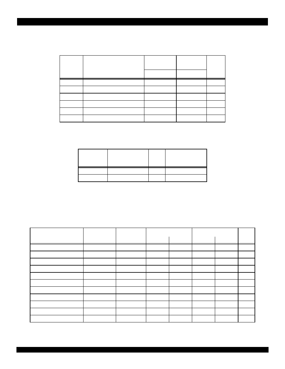
Clock Parameters--RC32364
Clock Parameters--RC32364
Clock Parameters--RC32364
Clock Parameters--RC32364
Note: Operation of the RC32364 is only guaranteed with the Phase Lock Loop enabled
Symbol
Rating
RC32364
3.3V
Ī
5%
RC32364
3.3V
Ī
5%
Unit
Commercial
Industrial
V
TERM
Terminal Voltage with respect to GND ≠0.5
1
to 4.0
1.
V
IN
minimum = ≠2.0V for pulse width less than 15ns. V
IN
should not exceed V
CC
+0.5 Volts.
≠0.5
1
to 4.0
V
T
C
Operating Temperature(case)
0 to +85
-40 to +85
į
C
T
BIAS
Case Temperature Under Bias
≠55 to +125
≠55 to +125
į
C
T
STG
Storage Temperature
≠55 to +125
≠55 to +125
į
C
I
IN
DC Input Current
20
2
2.
When V
IN
< 0V or V
IN
> V
CC
20
2
mA
I
OUT
DC Output Current
50
3
3.
Not more than one output should be shorted at a time. Duration of the short should not exceed 30 seconds.
50
3
mA
Grade
Temperature
Gnd
RC32364
V
CC Core & Vcc I/O
Commercial
0
į
C to +85
į
C (Case)
0V
3.3V
Ī
5%
Industrial
-40
į
C + 85
į
C (Case)
0V
3.3V
Ī
5%
Parameter
Symbol
Test
Conditions
RC32364 100MHz
RC32364 133MHz
Units
Min
Max
Min
Max
Pipeline clock frequency
PClk
80
100
80
133
MHz
MasterClock HIGH
t
MCHIGH
Transition
2ns
6
--
5
--
ns
MasterClock LOW
t
MCLOW
Transition
2ns
6
--
5
--
ns
MasterClock Frequency
--
--
10
50
10
67
MHz
MasterClock Period
t
MCP
--
20
100
15
100
ns
Clock Jitter for MasterClock
1
1.
Guaranteed by design
t
JitterIn
1
--
--
Ī
250
--
Ī
250
ps
MasterClock Rise Time
2
2.
Rise and Fall times are measured between 10% and 90%.
t
MCRise
--
--
3
--
3
ns
MasterClock Fall Time
2
t
MCFall
--
--
3
--
3
ns
JTAG Clock Period
t
TCK
--
100
--
100
--
ns
JTAG Clock High and Low Time t
TCKLOW,
t
TCKHIGH
--
40
--
40
--
ns
JTAG Clock Fall and Rise Time
t
TCKFall,
t
TCKRise
--
--
3
--
3
ns
13 of 21
June 20, 2000
79RC32364TM
*Notice: The information in this document is subject to change without notice
S
S
S
System Interface Parameters--RC32364
ystem Interface Parameters--RC32364
ystem Interface Parameters--RC32364
ystem Interface Parameters--RC32364
DC Electrical Characteristics -- Commercial/Industrial Temperature
DC Electrical Characteristics -- Commercial/Industrial Temperature
DC Electrical Characteristics -- Commercial/Industrial Temperature
DC Electrical Characteristics -- Commercial/Industrial Temperature
Ranges--RC32364
Ranges--RC32364
Ranges--RC32364
Ranges--RC32364
V
CC
Core & V
CC
I/O = 3.3V
Ī
5%; T
Case
= 0
į
C to +85
į
C Commercial, T
Case
= -40
į
C to +85
į
C Industrial
Parameter
Symbol
Test Conditions
RC32364
100MHz
RC32364
133MHz
Units
Min
Max
Min
Max
Data Output
tDO
= Max
--
6
--
6
ns
Data Output Hold
t
DOH
0.7
--
0.7
--
ns
Data Output for ALE
t
DOA
--
6
--
6
ns
Data Setup
t
DS
t
rise
= 2ns
t
fall
= 2ns
3
--
3
--
ns
Data Setup Special: Ack, Retry, BusErr t
DSS
6
--
5
--
ns
Data Hold
t
DH
0.5
--
0.5
--
ns
JTAG Clock Period
t
TCK,
t
3
100
--
100
--
ns
DCLK Clock Period
t
DCK,
t
11
12.5
--
12.5
--
ns
DCLK High, Low Time
t
DCK High,
t
9
t
DCK Low,
t
10
2.5
--
2.5
--
ns
DCLK Rise, Fall Time
t
DCK Rise,
t
15
t
DCK Fall,
t
15
--
3.5
--
3.5
ns
TDO Output Delay Time
t
TDODO,
t
4
--
6
--
6
ns
TDI Input Setup Time
t
TDIS,
t
5
4
--
4
--
ns
TDI Input Hold Time
t
TDIH,
t
6
2
--
2
--
ns
TPC Output Delay Time
t
TPCDO,
t
8
-1
6
-1
6
ns
PCST Output Delay Time
t
PCSTDO,
t
7
-1
6
-1
6
ns
TRST* Low TIme
t
TRSTLow,
t
12
100
--
100
--
ns
TRST* Removal TIme
t
TRSTR,
t
13
3
--
3
--
ns
Parameter
RC32364
100MHz
RC32364
133MHz
Conditions
Min
Max
Min
Max
V
OL
--
0.1V
--
0.1V
|I
OUT
|= 20uA
V
OH
V
CC
- 0.1V
--
V
CC
- 0.1V
--
V
OL
--
0.4V
--
0.4V
|I
OUT
|= 4mA
V
OH
2.4V
--
2.4V
--
V
IL
≠0.5V
0.2V
CC
≠0.5V
0.2V
CC
--
V
IH
0.7V
CC
V
CC
+0.3V
0.7V
CC
V
CC
+ 0.3V --
C
IN
--
10pF
--
10pF
--
C
OUT
--
10pF
--
10pF
--
I/O
LEAK
--
20uA
--
20uA
Input/Output Leakage

14 of 21
June 20, 2000
79RC32364TM
*Notice: The information in this document is subject to change without notice
Output Loading For AC Testing
Output Loading For AC Testing
Output Loading For AC Testing
Output Loading For AC Testing
Figure 3 Output Loading for AC Testing
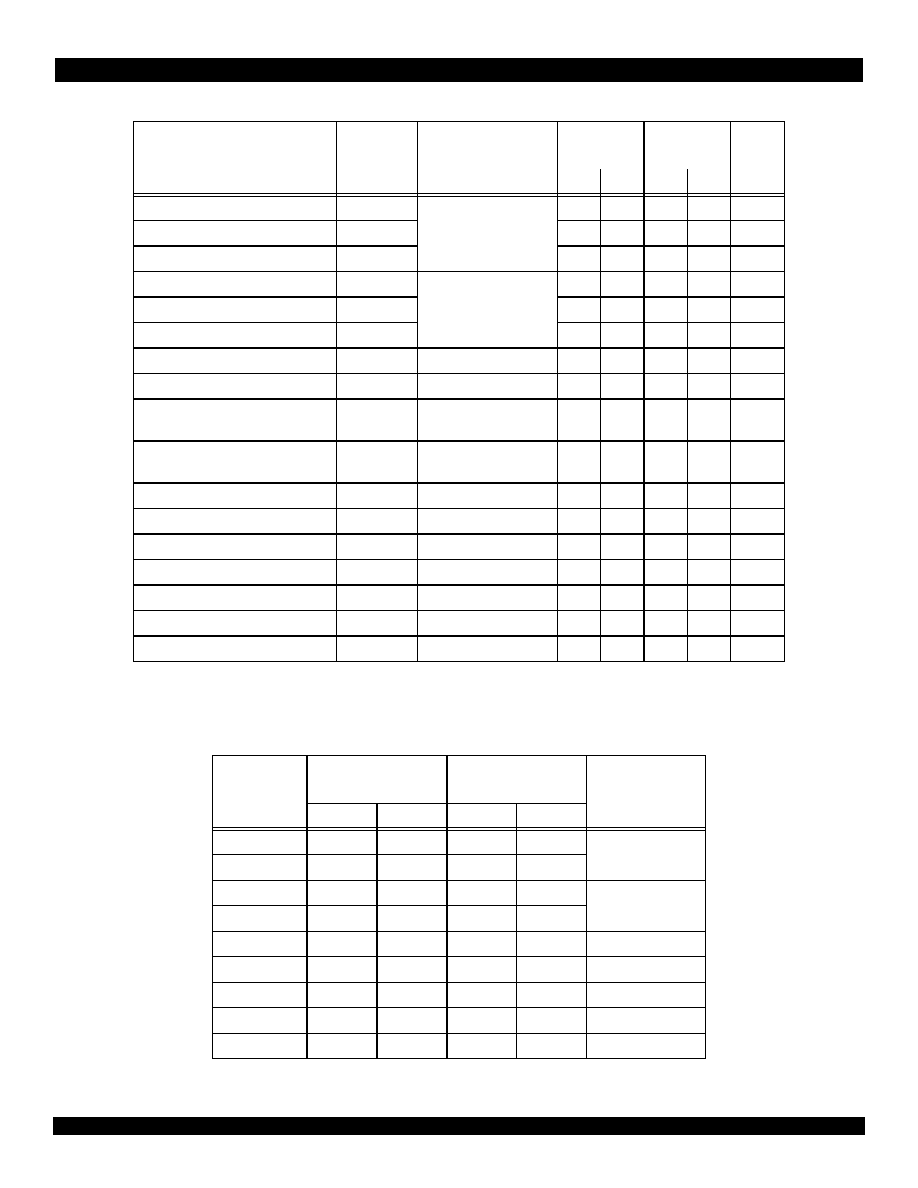
Power Consumption
Power Consumption
Power Consumption
Power Consumption --
--
--
-- RC32364
RC32364
RC32364
RC32364
Capacitive Load Deration -- RC32364
Capacitive Load Deration -- RC32364
Capacitive Load Deration -- RC32364
Capacitive Load Deration -- RC32364
Signal
Cld
All Signals
50 pF
Parameter
RC32364 100MHz
RC32364 133MHz
Conditions
Typical
Maximum
Typical
Maximum
System Condition:
100/50MHz
133/67MHz
--
I
CC
standby
1
1.
Executing wait instruction
50mA
90mA
50mA
90mA
C
L
= 50pF
T
c
= 25
o
C
Vcc core & Vcc I/O = 3.65V
active
160mA
180mA
200mA
250mA
C
L
= 50pF
T
C
= 25
o
C
Vcc core, Vcc I/O = 3.65V
P
power
dissipation
0.58W
0.6W
0.7Watt
0.9
C
L
= 50pF
T
C
= 25
o
C
Vcc core, Vcc I/O = 3.65V
Parameter Symbol
Test
Conditions
100MHz
133MHz
Units
Min
Max
Min
Max
Load Derate
C
LD
--
--
2
--
2
ns/25pF
≠
+
To Device
Under Test
C
LD
V
REF
+1.5V

15 of 21
June 20, 2000
79RC32364TM
*Notice: The information in this document is subject to change without notice
Power Curves
Power Curves
Power Curves
Power Curves
The following two graphs contain power curves that show power consumption at various bus frequencies.
Note: Only pipeline frequencies that are integer multiples (2x, 3x, etc.) of bus frequencies are supported.
Figure 4 Typical Power Usage - RC32364
Figure 5 Maximum Power Usage - RC32364
25.0
75.0
125.0
175.0
225.0
275.0
10 15 20 25 30 35 40 45 50 55 60 65
System Bus Speed (MHz)
ICC (mA
)
2x
3x
4x
5x
6x
7x
8x
2x
3x
4x
5x
6x
7x
8x
50.0
100.0
150.0
200.0
250.0
300.0
350.0
10 15 20 25 30 35 40 45 50 55 60 65
System Bus Speed (MHz)
ICC (mA
)
2x
3x
4x
5x
6x
7x
8x
2x
3x
4x
5x
6x
7x
8x

16 of 21
June 20, 2000
79RC32364TM
*Notice: The information in this document is subject to change without notice
Timing Characteristics -- RC32364
Timing Characteristics -- RC32364
Timing Characteristics -- RC32364
Timing Characteristics -- RC32364
Figure 6 System Clocks Data Setup, Output, and Hold timing
Figure 7 Mode Configuration Interface Reset Sequence
t
DS
t
DH
t
DO
t
DO
t
DOA
t
DSS
t
DH
MasterClock
Input
Output
ALE
Ack*
Retry*
BusErr*
t
DOH
t
MCKP
t
MCKHIGH
t
MCKLOW
t
MCRISE
t
MCFALL
VCC
ColdReset*
ModeBit[9:0]
Reset*
>= 100 ms
MasterClock
>= 10 ms
(MClk)
>= 64 MClk
cycles

17 of 21
June 20, 2000
79RC32364TM
*Notice: The information in this document is subject to change without notice
Standard JTAG Timing
Standard JTAG Timing
Standard JTAG Timing
Standard JTAG Timing
Figure 8 represents the timing diagram for the EJTAG interface signals.
The standard JTAG connector is a 10-pin connector providing 5 signal and 5 ground pins. For Enhanced JTAG, a 24-pin connector has been
chosen providing 12 signal pins and 12 ground pins. This guarantees the elimination of noise problems by incorporating a signal-ground type arrange-
ment.
Figure 8 Standard JTAG timing
TDI/DINT*
TMS
TDO/TPC,
TPC[8:2]
TDO
TDO
TPC
PCST[2:0],
TRST*
TCK
DCLK
PCST
t3
t14
t14
t1
t2
t15
t15
t9
t10
t5
t6
t4
t8
t7
t13
t12
t11
TPC,PCST[2:0] capture
Notes to diagram:
t1 = t
TCKlow
t2 = t
TCKHIGH
t3 = t
TCK
t4 = t
TDODO
t5 = t
TDIS
t6 = t
TDIH
t7 = t
PCSTDO
t8 = t
TPCDO
t9 = t
DCKHIGH
t10 = t
DCKLOW
t11 = t
DCK
t12 = t
TRSTDO
t13 = t
TRSTR
t14 = t
TCK RISE, tTCK FALL
t15 = t
DCK RISE,
t
DCK FALL

18 of 21
June 20, 2000
79RC32364TM
*Notice: The information in this document is subject to change without notice
Table 4 shows the pin numbering for the Standard EJTAG (EJT) connector. All the even numbered pins are connected to GROUND. The two right-
hand most columns show the target signal direction and the recommended termination at the target. Target termination resistors may be internal to the
chip or external on the board.
PIN
SIGNAL
TARGET
I/O
TERMINATION
1
1.
The value of the series resistor may depend on the actual PCB layout situation.
1
TRST* (optional)
Input
10 k
pull-down resistor
3 TDI/DINT*
Input
10
k
pull-up resistor
5
TDO/TPC
Output
33
series resistor
7
TMS
Input
10 k
pull-up resistor
9
TCK
Input
10 k
pull-up resistor
2
2.
TCK pull-up resistor is not required according to the JTAG (IEEE1149) standard. It is indicated here to prevent a floating
CMOS input when the EJTAG connector is unconnected.
11
RST*
Input
10 k
pull-up resistor
13
PCST[0]
Output
33
series
15
PCST[1]
Output
33
series
17
PCST[2]
Output
33
series
19
DCLK
Output
33
series
21
Debugboot
Input
10 k
pull-down resistor
23
VIO
Input
Must be connected to the VCC IO supply of the device.
Table 4 Pin Numbering of the JTAG and EJTAG Target Connector

19 of 21
June 20, 2000
79RC32364TM
*Notice: The information in this document is subject to change without notice
RC32364 Package Drawing -- 144-pin TQFP
RC32364 Package Drawing -- 144-pin TQFP
RC32364 Package Drawing -- 144-pin TQFP
RC32364 Package Drawing -- 144-pin TQFP
(Note: The RC32364 is available in a 144-pin thin quad flat pack (TQFP) package.)

20 of 21
June 20, 2000
79RC32364TM
*Notice: The information in this document is subject to change without notice
RC32364 Package Drawing
RC32364 Package Drawing
RC32364 Package Drawing
RC32364 Package Drawing
--
--
--
--
Page Two
Page Two
Page Two
Page Two

21 of 21
June 20, 2000
79RC32364TM
CORPORATE HEADQUARTERS
2975 Stender Way
Santa Clara, CA 95054
for SALES:
800-345-7015 or 408-727-6116
fax: 408-330-1748
www.idt.com
for Tech Support:
email: rischelp@idt.com
phone: 408-492-8208
The IDT logo is a registered trademark of Integrated Device Technology, Inc.
*Notice: The information in this document is subject to change without notice
Ordering Information
Ordering Information
Ordering Information
Ordering Information
Valid Combinations
Valid Combinations
Valid Combinations
Valid Combinations
IDT79RC32V364 - 100,133 DA
TQFP package, Commercial Temperature
IDT79RC32V364 - 100,133 DAI
TQFP package, Industrial Temperature
IDT79RCXX
YY
XXXX
999
A
A
Operating
Voltage
Device
Type
Speed
Package
Temp range/
Process
V
364
100
133
DA
Blank Commercial Temperature Range
(0
į
C
to +85
į
C
Case)
144-pin TQFP
100 MHz PClk
133 MHz PClk
3.3V +/-5%
Embedded Processor
Industrial Temperature Range
(-40
į
C
to +85
į
C
Case)
Product
Type
79RC32 32-bit Embedded
Microprocessor
I