
Integrated Device Technology, Inc.
MILITARY AND COMMERCIAL TEMPERATURE RANGES
OCTOBER 1996
©1996 Integrated Device Technology, Inc.
DSC-2720/4
IDT7134SA/LA
HIGH-SPEED
4K x 8 DUAL-PORT
STATIC RAM
FEATURES:
∑ High-speed access
-- Military: 25/35/45/55/70ns (max.)
-- Commercial: 20/25/35/45/55/70ns (max.)
∑ Low-power operation
-- IDT7134SA
Active: 500mW (typ.)
Standby: 5mW (typ.)
-- IDT7134LA
Active: 500mW (typ.)
Standby: 1mW (typ.)
∑ Fully asynchronous operation from either port
∑ Battery backup operation--2V data retention
∑ TTL-compatible; single 5V (
±
10%) power supply
∑ Available in several popular hermetic and plastic packages
∑ Military product compliant to MIL-STD-883, Class B
∑ Industrial temperature range (≠40
∞
C to +85
∞
C) is available,
tested to military electrical specifications
systems which cannot tolerate wait states or are designed to
be able to externally arbitrate or withstand contention when
both sides simultaneously access the same Dual-Port RAM
location.
The IDT7134 provides two independent ports with separate
control, address, and I/O pins that permit independent,
asynchronous access for reads or writes to any location in
memory. It is the user's responsibility to ensure data integrity
when simultaneously accessing the same memory location
from both ports. An automatic power down feature, controlled
by
CE
, permits the on-chip circuitry of each port to enter a very
low standby power mode.
Fabricated using IDT's CMOS high-performance
technology, these Dual-Port typically on only 500mW of
power. Low-power (LA) versions offer battery backup data
retention capability, with each port typically consuming 200
µ
W
from a 2V battery.
The IDT7134 is packaged on either a sidebraze or plastic
48-pin DIP, 48-pin LCC, 52-pin PLCC and 48-pin Ceramic
Flatpack. Military grade product is manufactured in compliance
with the latest revision of MIL-STD-883, Class B, making it
ideally suited to military temperature applications demanding
the highest level of performance and reliability.
The IDT logo is a registered trademark of Integrated Device Technology, Inc.
1
DESCRIPTION:
The IDT7134 is a high-speed 4K x 8 Dual-Port Static RAM
designed to be used in systems where on-chip hardware port
arbitration is not needed. This part lends itself to those
FUNCTIONAL BLOCK DIAGRAM
For latest information contact IDT's web site at www.idt.com or fax-on-demand at 408-492-8391.
6.04
COLUMN
I/O
COLUMN
I/O
MEMORY
ARRAY
LEFT SIDE
ADDRESS
DECODE
LOGIC
RIGHT SIDE
ADDRESS
DECODE
LOGIC
R/
W
L
OE
L
A
0L
- A
11L
I/O
0L
- I/O
7L
2720 drw 01
CE
L
A
0R
- A
11R
I/O
0R
- I/O
7R
OE
R
CE
R
R/
W
R
6.04
2
IDT7134SA/LA
HIGH-SPEED 4K x 8 DUAL-PORT STATIC RAM
MILITARY AND COMMERCIAL TEMPERATURE RANGES
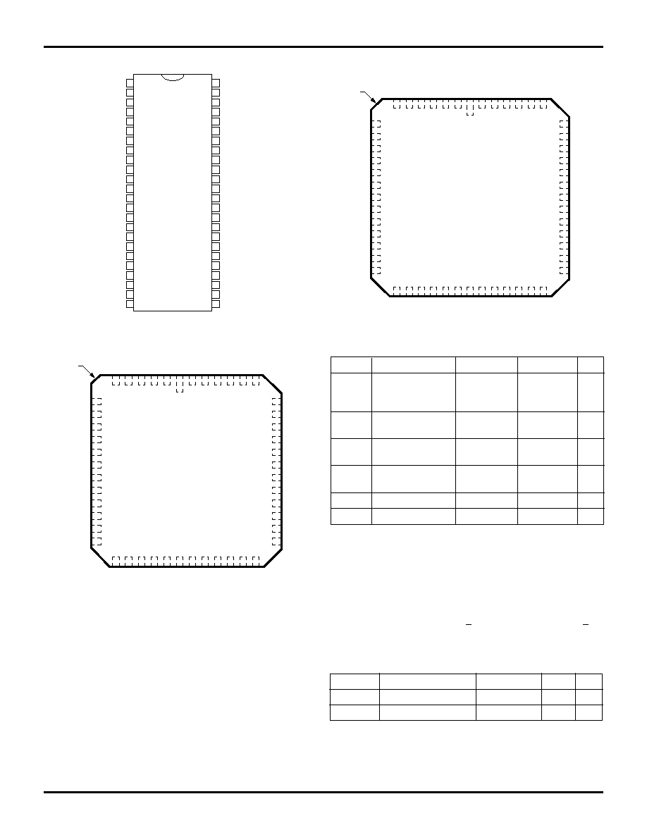
PIN CONFIGURATIONS
(1,2)
NOTES:
1. All Vcc pins must be connected to the power supply.
2. All GND pins must be connected to the ground supply.
3. This text does not indicate orientation of actual part-marking.
A
10R
2720 drw 02
I/O
0R
I/O
1R
I/O
2R
I/O
3R
I/O
4R
I/O
5R
I/O
6R
I/O
7R
A
9R
A
8R
A
7R
A
6R
A
4R
A
3R
A
2R
A
1R
A
0R
24
23
22
21
20
19
18
17
16
15
14
13
12
11
10
9
8
7
6
5
4
3
2
1
48
47
46
45
44
43
42
41
40
39
38
37
36
35
34
33
32
31
30
29
28
27
26
25
A
0L
A
1L
A
2L
A
3L
A
4L
A
5L
A
6L
A
7L
A
8L
A
9L
I/O
0L
I/O
1L
I/O
2L
I/O
3L
I/O
4L
I/O
5L
I/O
6L
I/O
7L
IDT7134
P48≠1
&
C48≠2
DIP
TOP
VIEW
(3)
CE
L
R/
W
L
OE
L
V
CC
A
5R
R
OE
A
11R
R/
W
R
CE
R
A
11L
A
10L
GND
2720 drw 04
IDT7134
L48-1
&
F48-1
LCC/Flatpack
TOP VIEW
(3)
INDEX
6 5
4 3
2
1
48 47 46 45 44 43
19 20 21 22 23
25 26 27 28 29 30
24
GND
I/O
3L
I/O
4L
I/O
5
L
I/O
6L
I/O
0R
I/O
1R
I/O
2R
I/O
3R
I/O
4R
I/O
5R
I/O
7L
A
1L
A
2L
A
3L
A
4L
A
5L
A
6L
A
7L
A
8L
A
9L
I/O
0L
I/O
1L
I/O
2L
A
0R
A
1R
A
2R
A
3R
A
4R
A
5R
A
6R
A
7R
A
8R
A
9R
I/O
6R
I/O
7R
42
41
40
39
38
37
36
35
34
33
32
31
7
8
9
10
11
12
13
14
15
16
17
18
A
0L
V
CC
OE
L
R/
W
L
CE
R
R/
W
R
CE
L
OE
R
A
10L
A
11L
A
11R
A
10R
2720 drw 03
IDT7134
J52-1
PLCC
TOP VIEW (3)
INDEX
N/C
GND
I/O
4L
I/O
5L
I/O
6L
I/O
7L
I/O
0R
I/O
1R
I/O
2R
I/O
3R
I/O
4R
I/O
5R
I/O
6R
OE
R
A
0R
A
1R
A
2R
A
3R
A
4R
A
5R
A
6R
A
7R
A
8R
A
9R
N/C
I/O
7R
46
45
44
43
42
41
40
39
38
37
36
35
34
I/O
3L
A
1L
A
2L
A
3L
A
4L
A
5L
A
6L
A
7L
A
8L
A
9L
I/O
0L
I/O
1L
I/O
2L
8
9
10
11
12
13
14
15
16
17
18
19
20
47
48
49
50
51
52
1
2
3
4
5
6
7
33
32
31
30
29
28
27
26
25
24
23
22
21
A
0L
V
CC
OE
L
R/
W
L
CE
R
R/
W
R
CE
L
A
10L
A
11L
A
11R
A
10R
N/C
N/C
ABSOLUTE MAXIMUM RATINGS
(1)
Symbol
Rating
Com'l.
Mil.
Unit
V
TERM
(2)
Terminal Voltage
≠0.5 to +7.0
≠0.5 to +7.0
V
with Respect
to Ground
T
A
Operating
0 to +70
≠55 to +125
∞
C
Temperature
T
BIAS
Temperature
≠55 to +125
≠65 to +135
∞
C
Under Bias
T
STG
Storage
≠55 to +125
≠65 to +150
∞
C
Temperature
P
T
(3)
Power Dissipation
1.5
1.5
W
I
OUT
DC Output Current
50
50
mA
2720 tbl 01
NOTES:
1. Stresses greater than those listed under ABSOLUTE MAXIMUM RATINGS
may cause permanent damage to the device. This is a stress rating only
and functional operation of the device at these or any other conditions
above those indicated in the operational sections of this specification is not
implied. Exposure to absolute maximum rating conditions for extended
periods may affect reliability.
2. V
TERM
must not exceed Vcc + 0.5V for more than 25%of the cycle time or
10 ns maximum, and is limited to < 20mA for the period of V
TERM
> Vcc
+0.5V.
CAPACITANCE
(1)
(T
A
= +25
∞
C, f = 1.0MHz)
Symbol
Parameter
Conditions
(2)
Max.
Unit
C
IN
Input Capacitance
V
IN
= 3dv
11
pF
C
OUT
Output Capacitance
V
OUT
= 3dv
11
pF
2720 tbl 02
NOTES:
1. This parameter is determined by device characterization but is not
production tested.
2. 3dv references the interpolated capacitance when the input and output
signals switch from 0V to 3V and from 3V to 0V.

6.04
3
IDT7134SA/LA
HIGH-SPEED 4K x 8 DUAL-PORT STATIC RAM
MILITARY AND COMMERCIAL TEMPERATURE RANGES
DC ELECTRICAL CHARACTERISTICS OVER THE
OPERATING TEMPERATURE AND SUPPLY VOLTAGE RANGE
(1)
(V
CC
= 5.0V
±
10%)
7134X20
(4)
7134X25
7134X35
7134X45
7134X55
7134X70
Symbol
Parameter
Test Conditions
Version Typ.
(2)
Max. Typ.
(2)
Max. Typ.
(2)
Max. Typ.
(2)
Max. Typ.
(2)
Max. Typ.
(2)
Max. Unit
I
CC
Dynamic Operating
CE
= V
IL
MIL.
S
--
--
160
310
150
300
140
280
140
270
140
270
mA
Current
Outputs Open
L
--
--
160
260
150
250
140
240
140
220
140
220
(Both Ports Active)
f = f
MAX
(3)
COM'L. S
170
280
160
280
150
260
140
240
140
240
140
240
L
170
240
160
220
150
210
140
200
140
200
140
200
I
SB1
Standby Current
CE
L
and
CE
R
= V
IH
MIL.
S
--
--
25
100
25
75
25
70
25
70
25
70
mA
(Both Ports--TTL
f = f
MAX
(3)
L
--
--
25
80
25
55
25
50
25
50
25
50
Level Inputs)
COM'L. S
25
110
25
80
25
75
25
70
25
70
25
70
L
25
80
25
50
25
45
25
40
25
40
25
40
I
SB2
Standby Current
CE
"A"
= V
IL
and
MIL.
S
--
--
95
210
85
200
75
190
75
180
75
180
mA
(One Port--TTL
CE
"B"
= V
IH
L
--
--
95
170
85
160
75
150
75
150
75
150
Level Inputs)
Active Port Outputs COM'L. S
105
180
95
180
85
170
75
160
75
160
75
160
Open, f = f
MAX
(3)
L
105
150
95
140
85
130
75
130
75
130
75
130
I
SB3
Full Standby Current Both Ports
CE
L
and MIL.
S
--
--
1.0
30
1.0
30
1.0
30
1.0
30
1.0
30
mA
(Both Ports--All
CE
R
V
CC
- 0.2V
L
--
--
0.2
10
0.2
10
0.2
10
0.2
10
0.2
10
CMOS Level Inputs) V
IN
V
CC
- 0.2V or
COM'L. S
1.0
15
1.0
15
1.0
15
1.0
15
1.0
15
1.0
15
V
IN
0.2V, f = 0
(3)
L
0.2
4.5
0.2
4.0
0.2
4.0
0.2
4.0
0.2
4.0
0.2
4.0
I
SB4
Full Standby Current One Port
CE
"A"
or
MIL.
S
--
--
95
210
85
190
75
180
75
170
75
170
mA
(One Port--All
CE
"B"
V
CC
- 0.2V
L
--
--
95
150
85
130
75
120
75
120
75
120
CMOS Level Inputs) V
IN
V
CC
- 0.2V or
COM'L. S
105
170
95
170
85
160
75
150
75
150
75
150
V
IN
0.2V
L
105
130
95
120
85
110
75
100
75
100
75
100
Active Port Outputs
Open, f = f
MAX
(3)
NOTES:
2720 tbl 06
1. "X" in part number indicates power rating (SA or LA).
2. V
CC
= 5V, T
A
= +25
∞
C for typical, and parameters are not production tested.
3. f
MAX
= 1/t
RC
= All inputs cycling at f = 1/t
RC
(except Output Enable). f = 0 means no address or control lines change. Applies only to inputs at CMOS level
standby I
SB3.
4. (Commercial only) 0
∞
C to +70
∞
C temperature range.
RECOMMENDED OPERATING
TEMPERATURE AND SUPPLY VOLTAGE
Ambient
Grade
Temperature
GND
V
CC
Military
≠55
∞
C to +125
∞
C
0V
5.0V
±
10%
Commercial
0
∞
C to +70
∞
C
0V
5.0V
±
10%
2720 tbl 03
RECOMMENDED DC OPERATING CONDITIONS
Symbol
Parameter
Min.
Typ.
Max.
Unit
V
CC
Supply Voltage
4.5
5.0
5.5
V
GND
Ground
0
0
0
V
V
IH
Input High Voltage
2.2
--
6.0
(2)
V
V
IL
Input Low Voltage
≠0.5
(1)
--
0.8
V
NOTES:
2720 tbl 04
1. V
IL
(min.) > ≠1.5V for pulse width less than 10ns.
2. V
TERM
must not exceed Vcc + 0.5V.
DC ELECTRICAL CHARACTERISTICS OVER THE
OPERATING TEMPERATURE AND SUPPLY VOLTAGE
(V
CC
= 5V
±
10%)
IDT7134SA
IDT7134LA
Symbol
Parameter
Test Conditions
Min.
Max.
Min.
Max.
Unit
|I
LI
|
Input Leakage Current
(1)
V
CC
= 5.5V, V
IN
= 0V to V
CC
--
10
--
5
µ
A
|I
LO
|
Output Leakage Current
CE
= V
IH
, V
OUT
= 0V to V
CC
--
10
--
5
µ
A
V
OL
Output Low Voltage
I
OL
= 6mA
--
0.4
--
0.4
V
I
OL
= 8mA
--
0.5
--
0.5
V
V
OH
Output High Voltage
I
OH
= ≠4mA
2.4
--
2.4
--
V
NOTE:
2720 tbl 05
1. At Vcc
2.0V input leakages are undefined.
6.04
4
IDT7134SA/LA
HIGH-SPEED 4K x 8 DUAL-PORT STATIC RAM
MILITARY AND COMMERCIAL TEMPERATURE RANGES
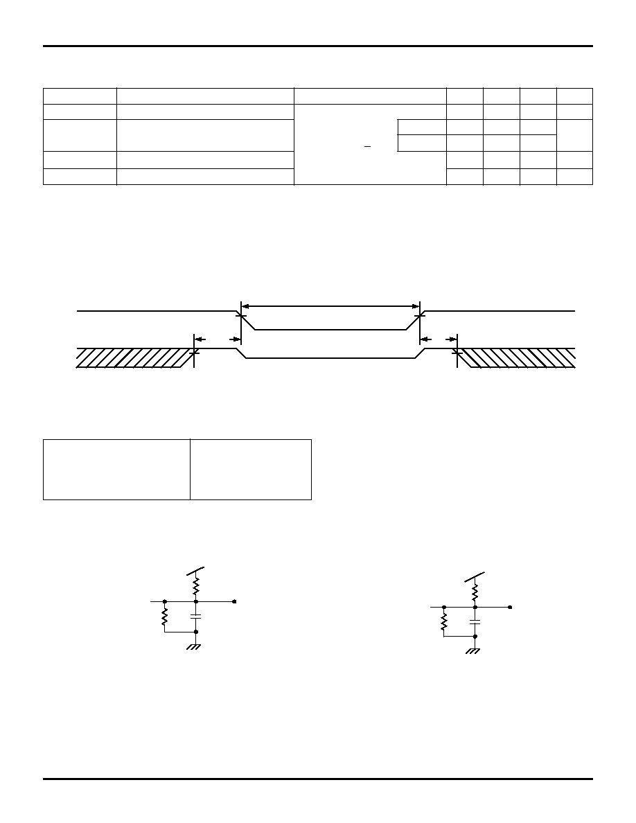
DATA RETENTION CHARACTERISTICS OVER ALL TEMPERATURE RANGES
(LA Version Only) V
LC
= 0.2V, V
HC
= V
CC
- 0.2V
Symbol
Parameter
Test Condition
Min.
Typ.
(1)
Max.
Unit
V
DR
VCC for Data Retention
V
CC
= 2V
2.0
--
--
V
I
CCDR
Data Retention Current
CE
V
HC
MIL.
--
100
4000
µ
A
V
IN
V
HC
or < V
LC
COM'L.
--
100
1500
t
CDR
(3)
Chip Deselect to Data Retention Time
0
--
--
ns
t
R
(3)
Operation Recovery Time
t
RC
(2)
--
--
ns
NOTES:
2720 tbl 07
1. V
CC
= 2V, T
A
= +25
∞
C, and are not production tested.
2. t
RC
= Read Cycle Time.
3. This parameter is guaranteed by device characterization, but not production tested.
DATA RETENTION WAVEFORM
AC TEST CONDITIONS
Input Pulse Levels
GND to 3.0V
Input Rise/Fall Times
5ns
Input Timing Reference Levels
1.5V
Output Reference Levels
1.5V
Output Load
Figures 1 and 2
2720 tbl 08
Figure 1. AC Output Test Load
Figure 2. Output Test Load
(for t
LZ
, t
HZ
, t
WZ
, t
OW
)
+5V
1250
30pF *
775
DATA
OUT
2720 drw 06
+5V
1250
5pF *
775
DATA
OUT
2720 drw 07
*Including scope and jig
V
CC
CE
DATA RETENTION MODE
4.5V
4.5V
V
DR
2V
V
DR
V
IH
V
IH
t
CDR
t
R
2720 drw 05
6.04
5
IDT7134SA/LA
HIGH-SPEED 4K x 8 DUAL-PORT STATIC RAM
MILITARY AND COMMERCIAL TEMPERATURE RANGES
AC ELECTRICAL CHARACTERISTICS OVER THE
OPERATING TEMPERATURE AND SUPPLY VOLTAGE
(4)
(CONT'D)
7134X45
7134X55
7134X70
Symbol
Parameter
Min.
Max.
Min.
Max.
Min.
Max.
Unit
READ CYCLE
t
RC
Read Cycle Time
45
--
55
--
70
--
ns
t
AA
Address Access Time
--
45
--
55
--
70
ns
t
ACE
Chip Enable Access Time
--
45
--
55
--
70
ns
t
AOE
Output Enable Access Time
--
25
--
30
--
40
ns
t
OH
Output Hold from Address Change
0
--
0
--
0
--
ns
t
LZ
Output Low-Z Time
(1, 2)
5
--
5
--
5
--
ns
t
HZ
Output High-Z Time
(1, 2)
--
20
--
25
--
30
ns
t
PU
Chip Enable to Power Up Time
(2)
0
--
0
--
0
--
ns
t
PD
Chip Disable to Power Down Time
(2)
--
45
--
50
--
50
ns
NOTES:
2720 tbl 09
1. Transition is measured
±
500mV from Low or High-impedance voltage with the Output Test Load (Figure 2).
2. This parameter is guaranteed by device characterization, but is not production tested.
3. (Commercial only) 0
∞
C to +70
∞
C temperature range only.
4. "X" in part number indicates power rating (SA or LA).
TIMING WAVEFORM OF READ CYCLE NO. 1, EITHER SIDE
(1, 2, 3)
AC ELECTRICAL CHARACTERISTICS OVER THE
OPERATING TEMPERATURE AND SUPPLY VOLTAGE
(4)
7134X20
(3)
7134X25
7134X35
Symbol
Parameter
Min.
Max.
Min.
Max.
Min.
Max.
Unit
READ CYCLE
t
RC
Read Cycle Time
20
--
25
--
35
--
ns
t
AA
Address Access Time
--
20
--
25
--
35
ns
t
ACE
Chip Enable Access Time
--
20
--
25
--
35
ns
t
AOE
Output Enable Access Time
--
15
--
15
--
20
ns
t
OH
Output Hold from Address Change
0
--
0
--
0
--
ns
t
LZ
Output Low-Z Time
(1, 2)
0
--
0
--
0
--
ns
t
HZ
Output High-Z Time
(1, 2)
--
15
--
15
--
20
ns
t
PU
Chip Enable to Power Up Time
(2)
0
--
0
--
0
--
ns
t
PD
Chip Disable to Power Down Time
(2)
--
20
--
25
--
35
ns
NOTES:
1. Timing depends on which signal is asserted last,
OE
or
CE
.
2. Timing depends on which signal is de-asserted first,
OE
or
CE
.
3. R/
W
= V
IH
.
ADDRESS
DATA
OUT
PREVIOUS DATA VALID
DATA VALID
t
OH
t
OH
t
AA
t
RC
2720 drw 08
6.04
6
IDT7134SA/LA
HIGH-SPEED 4K x 8 DUAL-PORT STATIC RAM
MILITARY AND COMMERCIAL TEMPERATURE RANGES
TIMING WAVEFORM OF READ CYCLE NO. 2, EITHER SIDE
(1, 3)
2720 drw 09
CE
DATA
OUT
VALID DATA
(4)
t
PD
t
AOE
(4)
t
ACE
OE
t
HZ
(2)
t
LZ
(1)
t
LZ
(1)
t
PU
50%
50%
I
CC
I
SB
CURRENT
t
HZ
(2)
NOTES:
1. Timing depends on which signal is asserted last,
OE
or
CE
.
2. Timing depends on which signal is de-asserted first,
OE
or
CE
.
3. R/
W
= V
IH
.
4. Start of valid data depends on which timing becomes effective , t
AOE
, t
ACE
or t
AA
5. t
AA
for RAM Address Access and t
SAA
for Semaphore Address Access.
AC ELECTRICAL CHARACTERISTICS OVER THE
OPERATING TEMPERATURE AND SUPPLY VOLTAGE
(6)
7134X20
(5)
7134X25
7134X35
Symbol
Parameter
Min.
Max.
Min.
Max.
Min.
Max.
Unit
WRITE CYCLE
t
WC
Write Cycle Time
20
--
25
--
35
--
ns
t
EW
Chip Enable to End-of-Write
15
--
20
--
30
--
ns
t
AW
Address Valid to End-of-Write
15
--
20
--
30
--
ns
t
AS
Address Set-up Time
0
--
0
--
0
--
ns
t
WP
Write Pulse Width
15
--
20
--
25
--
ns
t
WR
Write RecoveryTime
0
--
0
--
0
--
ns
t
DW
Data Valid to End-of-Write
15
--
15
--
20
--
ns
t
HZ
Output High-Z Time
(1, 2)
--
15
--
15
--
20
ns
t
DH
Data Hold Time
(3)
0
--
0
--
3
--
ns
t
WZ
Write Enabled to Output in High-Z
(1, 2)
--
15
--
15
--
20
ns
t
OW
Output Active from End-of-Write
(1, 2, 3)
3
--
3
--
3
--
ns
t
WDD
Write Pulse to Data Delay
(4)
--
40
--
50
--
60
ns
t
DDD
Write Data Valid to Read Data Delay
(4, 7)
--
30
--
30
--
35
ns
NOTES:
2720 tbl 10
1. Transition is measured
±
500mV from Low or High-impedance voltage with Output Test Load (Figure 2).
2. This parameter is guaranteed by device characterization, but is not production tested.
3. The specification for t
DH
must be met by the device supplying write data to the RAM under all operating conditions. Although t
DH
and t
OW
values will vary
over voltage and temperature, the actual t
DH
will always be smaller than the actual t
OW
.
4. Port-to-port delay through RAM cells from writing port to reading port, refer to "Timing Waveform of Write with Port-to-Port Read".
5. (Commercial only), 0
∞
C to +70
∞
C temperature range .
6. "X" in part number indicates power rating (SA or LA).
7. t
DDD
= 35ns for military temperature range.
6.04
7
IDT7134SA/LA
HIGH-SPEED 4K x 8 DUAL-PORT STATIC RAM
MILITARY AND COMMERCIAL TEMPERATURE RANGES
AC ELECTRICAL CHARACTERISTICS OVER THE
OPERATING TEMPERATURE AND SUPPLY VOLTAGE
(6)
(CONT'D)
7134X45
7134X55
7134X70
Symbol
Parameter
Min.
Max.
Min.
Max.
Min.
Max.
Unit
WRITE CYCLE
t
WC
Write Cycle Time
45
--
55
--
70
--
ns
t
EW
Chip Enable to End-of-Write
40
--
50
--
60
--
ns
t
AW
Address Valid to End-of-Write
40
--
50
--
60
--
ns
t
AS
Address Set-up Time
0
--
0
--
0
--
ns
t
WP
Write Pulse Width
40
--
50
--
60
--
ns
t
WR
Write RecoveryTime
0
--
0
--
0
--
ns
t
DW
Data Valid to End-of-Write
20
--
25
--
30
--
ns
t
HZ
Output High-Z Time
(1, 2)
--
20
--
25
--
30
ns
t
DH
Data Hold Time
(3)
3
--
3
--
3
--
ns
t
WZ
Write Enabled to Output in High-Z
(1, 2)
--
20
--
25
--
30
ns
t
OW
Output Active from End-of-Write
(1, 2, 3)
3
--
3
--
3
--
ns
t
WDD
Write Pulse to Data Delay
(4)
--
70
--
80
--
90
ns
t
DDD
Write Data Valid to Read Data Delay
(4)
--
45
--
55
--
70
ns
NOTES:
1. Transition is measured
±
500mV from Low or High-impedance voltage with Output Test Load (Figure 2).
2. This parameter is guaranteed by device characterization, but is not production tested.
3. The specification for t
DH
must be met by the device supplying write data to the RAM under all operating conditions. Although t
DH
and t
OW
values will vary
over voltage and temperature, the actual t
DH
will always be smaller than the actual t
OW
.
4. Port-to-port delay through RAM cells from writing port to reading port, refer to "Timing Waveform of Write with Port-to-Port Read".
5. (Commercial only), 0
∞
C to +70
∞
C temperature range .
6. "X" in part number indicates power rating (SA or LA).
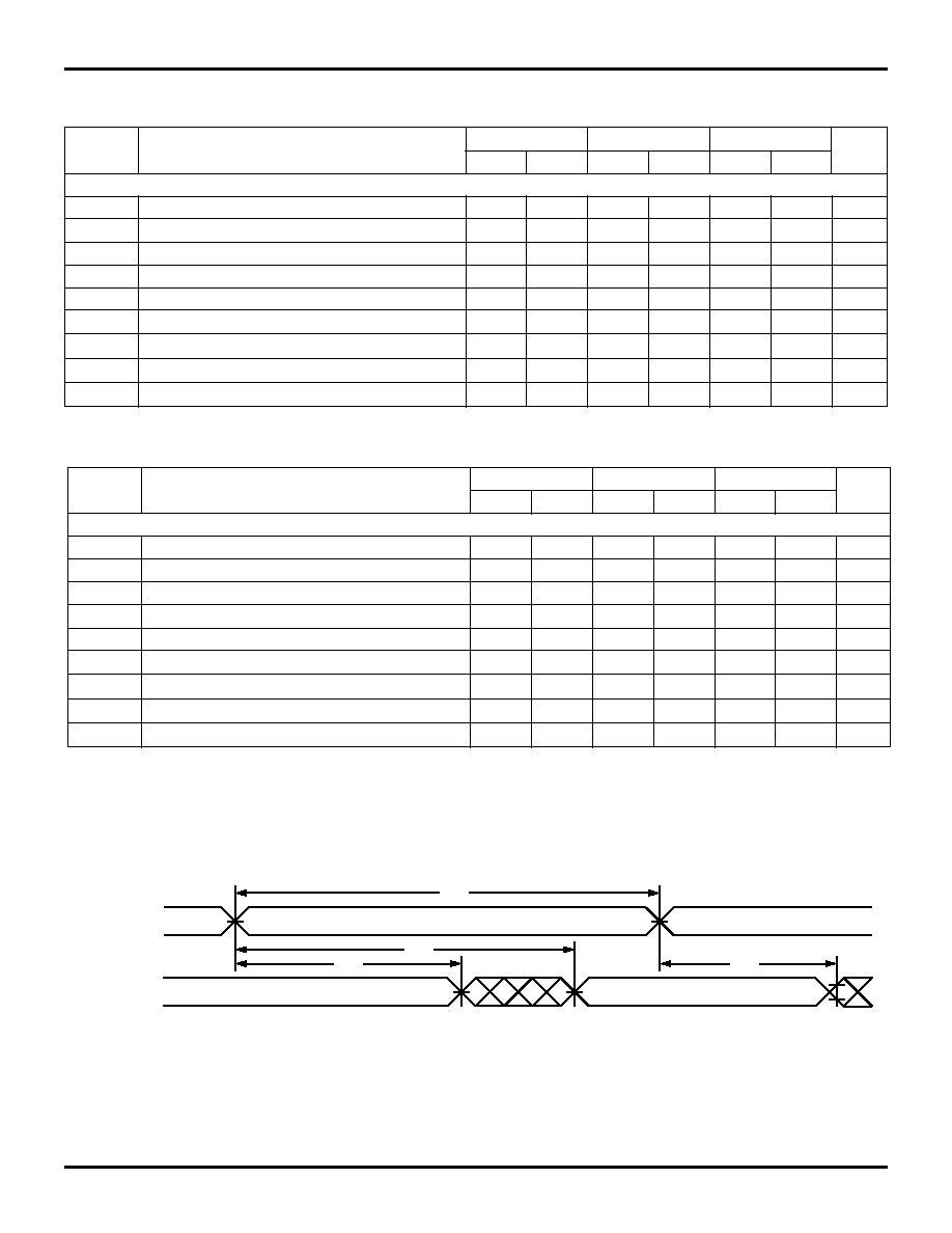
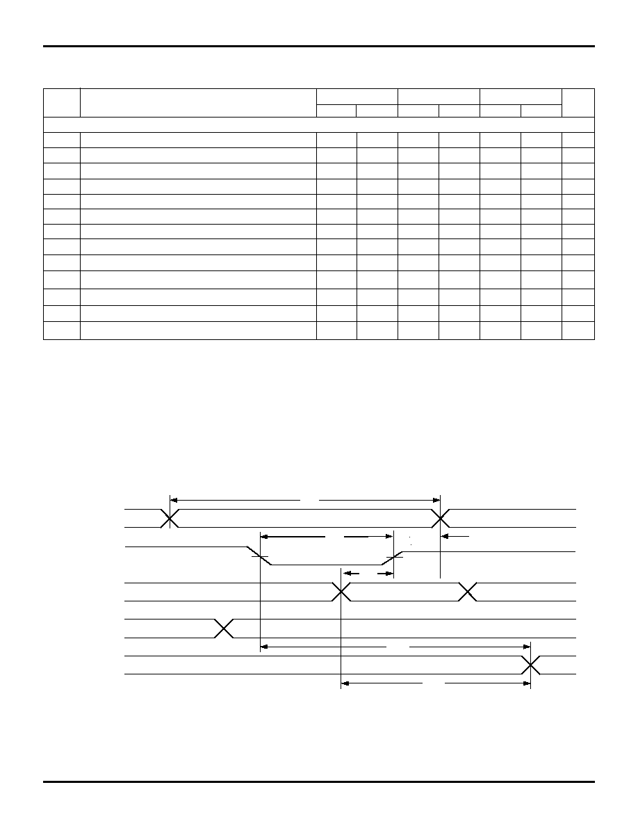
TIMING WAVEFORM OF WRITE WITH PORT-TO-PORT READ
(1)
2720 tbl 10
2.
CE
L =
CE
R =
V
IL.
OE
"B"
= V
IL.
3. Port "A" may be either left or right port. Port "B" is the opposite from port "A".
NOTES:
1. Write cycle parameters should be adhered to, in order to ensure proper writing.
2720 drw 10
R/
W
"A"
VALID
t
WC
MATCH
VALID
MATCH
t
WP
t
DW
t
WDD
t
DDD
ADDR
"A"
DATA
IN "A"
DATA
OUT "B"
ADDR
"B"
t
AW

6.04
8
IDT7134SA/LA
HIGH-SPEED 4K x 8 DUAL-PORT STATIC RAM
MILITARY AND COMMERCIAL TEMPERATURE RANGES
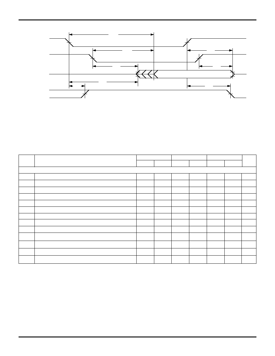
TIMING WAVEFORM OF WRITE CYCLE NO. 1, R/
W
W
W
W
W
CONTROLLED TIMING
(1, 5, 8)
TIMING WAVEFORM OF WRITE CYCLE NO. 2,
CE
CE
CE
CE
CE
CONTROLLED TIMING
(1, 5)
NOTES:
1. R/
W
or
CE
must be High during all address transitions.
2. A write occurs during the overlap (t
EW
or t
WP
) of a
CE
=V
IL
and R/
W
= V
IL
.
3. t
WR
is measured from the earlier of
CE
or R/
W
going High to the end-of-write cycle.
4. During this period, the I/O pins are in the output state, and input signals must not be applied.
5. If the
CE
Low transition occurs simultaneously with or after the R/
W
Low transition, the outputs remain in the High-impedance state.
6. Timing depends on which enable signal (
CE
or R/
W
)is asserted last.
7. This parameter is guaranteed by device characterization, but is not production tested. Transition is measured + 500mV from steady state with the Output
Test Load (Figure 2).
8. If
OE
is Low during a R/
W
controlled write cycle, the write pulse width must be the larger of t
WP
or (t
WZ
+ t
DW
) to allow the I/O drivers to turn off data to
be placed on the bus for the required t
DW
. If
OE
is High during an R/
W
controlled write cycle, this requirement does not apply and the write pulse can be
as short as the specified t
WP
.
2720 drw 12
R/
W
t
WC
ADDRESS
DATA
IN
CE
1.20 in
t
DW
t
WR(3)
t
DH
t
EW(2)
t
AW
t
AS(6)
CE
2720 drw 11
t
AW
t
AS(6)
t
DW
DATA
IN
ADDRESS
t
WC
R/
W
t
WP
t
DH
DATA
OUT
t
WZ
(7)
(4)
(4)
(2)
t
OW
OE
(7)
t
HZ
t
LZ
(7)
t
HZ
t
WR(3)

6.04
9
IDT7134SA/LA
HIGH-SPEED 4K x 8 DUAL-PORT STATIC RAM
MILITARY AND COMMERCIAL TEMPERATURE RANGES
ORDERING INFORMATION
TRUTH TABLE I ≠ READ/WRITE CONTROL
(2)
Left or Right Port
(1)
R/
W
W
W
W
W
CE
CE
CE
CE
CE
OE
OE
OE
OE
OE
D
0-7
Function
X
H
X
Z
Port Disabled and in Power
Down Mode, I
SB2
or I
SB4
X
H
X
Z
CE
R
=
CE
L
= H, Power Down
Mode, I
SB1
or I
SB3
L
L
X
DATA
IN
Data on port written into
memory
H
L
L
DATA
OUT
Data in memory output on port
X
X
H
Z
High impedance outputs
2720 tbl 11
NOTES:
1. A
OL
- A
11L
A
OR
- A
11R
2. "H" = HIGH, "L" = LOW, "X" = Don't Care, and "Z" = High-impedance
FUNCTIONAL DESCRIPTION
The IDT7134 provides two ports with separate control,
address, and I/O pins that permit independent access for
reads or writes to any location in memory. These devices have
an automatic power down feature controlled by
CE
. The
CE
controls on-chip power down circuitry that permits the
respective port to go into standby mode when not selected
(
CE
high). When a port is enabled, access to the entire
memory array is permitted. Each port has its own Output
Enable control (
OE
). In the read mode, the port's
OE
turns on
the output drivers when set LOW. Non-contention READ/
WRITE conditions are illustrated in the table below.
2720 drw 13
IDT
XXXX
A
999
A
A
Device Type
Power
Speed
Package
Process/
Temperature
Range
Blank
B
P
C
J
L48
F
20
25
35
45
55
70
LA
SA
7134
Commercial (0
∞
C to +70
∞
C)
Military (≠55
∞
C to +125
∞
C)
Compliant to MIL-STD-883, Class B
48-pin Plastic DIP (P48-1)
48-pin Ceramic DIP (C48-2)
52-pin PLCC (J52-1)
48-pin LCC (L48-1)
48-pin Ceramic Flatpack (F48-1)
Speed in nanoseconds
Low Power
Standard Power
32K (4K x 8-Bit) Dual-Port RAM
Commercial Only