
TECHNICAL DATA
1
I N T E G R A L
2 x 12 W Hi-Fi Audio Power Amplifiers With Mute
The ILA2616 are dual power amplifiers. The ILA2616 is supplied in a 9-lead single-in-line (SIL9) plastic
power package (SOT131). They have been especially designed for mains fed applications, such as stereo radio and
stereo TV.
FEATURES
∑
Requires very few external components
∑
No switch-on/switch-off clicks
∑
Input mute during switch-on and switch-off
∑
Low offset voltage between output and ground
∑
Excellent gain balance of both amplifiers
∑
Hi-fi in accordance with IEC 268 and DIN 45500
∑
Short-circuit proof and thermal protected
∑
Mute possibility.
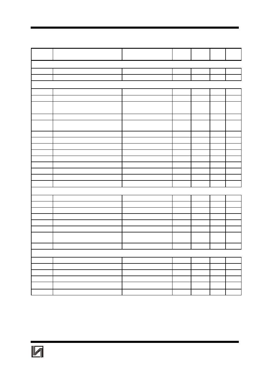
QUICK REFERENCE DATA (
Stereo application)
SYMBOL
PARAMETER
CONDITIONS
MIN
TYP
MAX
UNIT
±Vp
supply voltage range
7.5
-
21
V
Po
output power
Vp = ±16 V; THD = 0.5%
-
12
-
W
Gv
internal voltage gain
-
30
-
dB
|Gv|
channel unbalance
-
0.2
-
dB
channel separation
-
70
-
dB
SVRR
supply voltage ripple rejection
-
60
-
dB
Vno
noise output voltage
-
70
-
nV
ORDERING INFORMATION
EXTENDED TYPE
PACKAGE
NUMBER
PINS
PIN POSITION
MATERIAL
CODE
ILA2616
9
SIL
plastic
SOT131
PAD DESCRIPTION
SYMBOL
PIN
DESCRIPTION
-INV1
1
non-inverting input 1
MUTE
2
mute input
1/2Vp/GND
3
1/2 supply voltage or ground
OUT1
4
output 1
-Vp
5
supply voltage (negative)
OUT2
6
output 2
+Vp
7
supply voltage (positive)
INV1,2
8
inverting inputs 1 and 2
-INV2
9
non-inverting input 2
ILA2616
ILA2616
ILA2616
2
I N T E G R A L
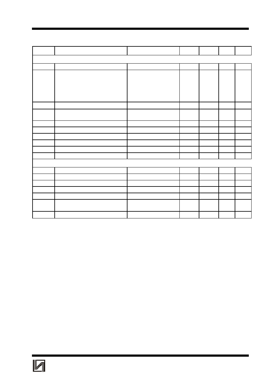
CHARACTERISTICS
SYMBOL
PARAMETER
CONDITIONS
MIN
TYP
MAX
UNIT
Supply
±Vp
supply voltage range
-
16
21
V
I
ORM
repetitive peak output current
-
2.2
-
A
Operating position; note 1
±Vp
supply voltage range
7.5
16
21
V
I
P
total quiescent current
R
L
=
18
40
70
mA
Po
output power
THD = 0.5%
10
12
-
W
THD = 10%
12
15
-
W
THD
total harmonic distortion
Po=6W
-
0.15
0.2
%
B
power bandwidth
THD = 0.5%; note 2
-
20 to
-
Hz
20 000
Gv
voltage gain.
29
30
31
dB
|Gv|
gain unbalance
-
0.2
1
dB
Vno
noise output voltage
note3
-
70
140
µ
V
|Zi|
input impedance
14
20
26
k
SVRR
supply voltage ripple rejection
note 4
40
60
-
dB
channel separation
Rs=
O
46
70
-
dB
Ibias
input bias current
-
0.3
-
µ
A
|
V
GND
|
DC output offset voltage
-
30
200
mV
|
V
4-6
|
DC output offset voltage
between two channels
-
4
150
mV
MUTE
POSITION (AT I
MUTE
300
µ
A)
V
o
output voltage
V
I
= 600 mV
-
0.3
1.0
mV
Z
2-7
mute input impedance
note 7
6.7
9
11.3
k
I
p
total quiescent current
R
L
=
18
40
70
mA
Vno
noise output voltage
note3
-
70
140
µ
V
SVRR
supply voltage ripple rejection
note 4
40
55
-
dB
|
V
GND
|
DC output offset voltage
-
40
200
mV
|
V
off
|
offset voltage with respect to operat-
-
4
150
mV
position
I
2
current if pin 2 is connected to pin 5
-
-
8.2
mA
Mute position; note 5
±Vp
supply voltage range
2
-
5.8
V
Ip
total quiescent current.
R
L
=
9
30
40
mA
Vo
output voltage
V
I
= 600 mV
-
0.3
1.0
mV
Vno
noise output voltage
note 3
-
70
140
µ
V
SVRR
supply voltage ripple rejection
note 4
40
55
-
dB
|
V
GND
|
DC output offset voltage
-
40
200
mV
ILA2616
3
I N T E G R A L
SYM-
BOL
PARAMETER
CONDITIONS
MIN
TYP
MAX
UNIT
Operating position; note 6
I
P
total quiescent current
18
40
70
mA
P
O
output power
THD = 0.5%
5
6
-
W
THD = 10%
6.5
8
-
W
THD = 0.5%; R
L
= 4
-
10
-
W
THD = 10%; R
L
= 4
-
14
-
W
THD
total harmonic distortion
Po=4W
-
0.13
0.2
%
B
power bandwidth
THD = 0.5%; note 2
-
40 to
-
Hz
20 000
G
V
voltage gain
29
30
31
dB
|Gv|
gain unbalance
-
0.2
1
dB
Vno
noise output voltage
note3
-
70
140
µ
V
|Zi|
input impedance
14
20
26
k
SVRR
supply voltage ripple rejection
35
44
-
dB
channel separation
-
45
-
dB
MUTE POSITION (I
MUTE
300
)
µ
A
V
Q
output voltage
V
I
= 600 mV
-
0.3
1.0
mV
Z
2-7
mute input impedance
note 7
6.7
9
11.3
k
I
P
total quiescent current
18
40
70
mA
Vno
noise output voltage
note 3
-
70
140
µ
V
SVRR
supply voltage ripple rejection .
note 4
35
44
-
dB
|
Voff|
offset voltage with respect to op-
-
4
150
mV
position
I
2
current if pin 2 is connected to pin 5
-
-
8.2
mA
Notes to the characteristics
1. Vp = ±16 V; R
L
.
= 8
; Tamb = 25 ∞C; f =1 kHz; symmetrical power supply
I
MUTE
< 30
µ
A
2. The power bandwidth is measured at an output power of P
O
max -3 dB
3. The noise output voltage (RMS value) is measured at Rs = 2 k
, unweighted (20 Hz to 20 kHz)
4. The ripple rejection is measured at Rs = 0 and f = 100 Hz to 20 kHz. The ripple voltage (200 mV) is applied in
phase to the positive and the negative supply rails. With asymmetrical power supplies, the ripple rejection is
measured at f = 1 kHz
5. ±Vp = 4 V; R
L
= 8
; Tamb = 25 ∞C; f =1 kHz; symmetrical power supply.
6. Vp = 24 V; R
L
= 8
; Tamb = 25 ∞C; f =1 kHz; asymmetrical power supply I
MUTE
< 30
µ
A
7. The internal network at pin 2 is a resistor devider of typical 4 k
and 5 k
to the positive supply rail. At the
connection of the 4 k
and 5 k
resistor a zener diode of typical 6.6 V is also connected to the positive supply
rail. The spread of the zener voltage is 6.1 to 7.1 V.

